

Manitou MT-X 1235 1440 1740 Repair Manual – Series 3-E3 & 4-E3 Telehandler Service Manual PDF
Original price was: $34.95.$19.95Current price is: $19.95.
Complete Manitou repair manual for the MT-X 1235 ST, MT-X 1740 SLT (Serie 3-E3) and MT-X 1440 SLT (Serie 4-E3) telehandlers. Document 647385EN covers engine, transmission, axle, brakes, boom, hydraulics, electrics, cab and attachments, with full hydraulic and electrical schematics. Instant PDF download.
Description
Manitou MT-X 1235 1440 1740 Repair Manual – Series 3-E3 & 4-E3 Telehandler Service Manual
The Manitou MT-X 1235 1440 1740 Repair Manual is the complete workshop document for three Manitou telehandler families: the MT-X 1235 ST and MT-X 1740 SLT of Serie 3-E3, and the MT-X 1440 SLT of Serie 4-E3. Issued under reference 647385EN and dated 04/07/2011, it runs from general safety through the engine, transmission, axle, brake, boom, hydraulic, electrical, cab and frame chapters and finishes with options and attachments. Both the 80 CV and 100 CV Perkins 1104D Euro 3 engines are addressed.
File Details
- Manual type: Repair manual
- Brand: Manitou
- Models covered: MT-X 1235 ST and MT-X 1740 SLT (Serie 3-E3), MT-X 1440 SLT (Serie 4-E3)
- Engines: Perkins 1104D Euro 3 – 80 CV and 100 CV
- Document number: 647385EN
- Issue date: 04/07/2011
- Language: English
- Format: PDF
Chapters Covered
- General characteristics and safety – general instructions and safety notice
- Engine – characteristics and specifications; control and adjustment
- Transmission – control and adjustment; characteristics and specifications; sections and diagrams; troubleshooting; specific transmission tooling
- Axle – characteristics and specifications; control and adjustment; troubleshooting; specific tooling
- Brake – service brake; parking brake (cable brake); parking brake (negative hydraulic brake); specific brake tooling
- Boom – control and adjustment; lower, intermediate and upper hose replacement; inner telescopic cylinder removal; outer telescopic cylinder removal; tilt cylinder removal; arm pad removal and refitting
- Hydraulic – hydraulic schematic diagrams; specific hydraulic tooling
- Electric – electrical schematic diagrams; specific electrical tooling
- Driver’s cab
- Frame – body
- Options – attachments
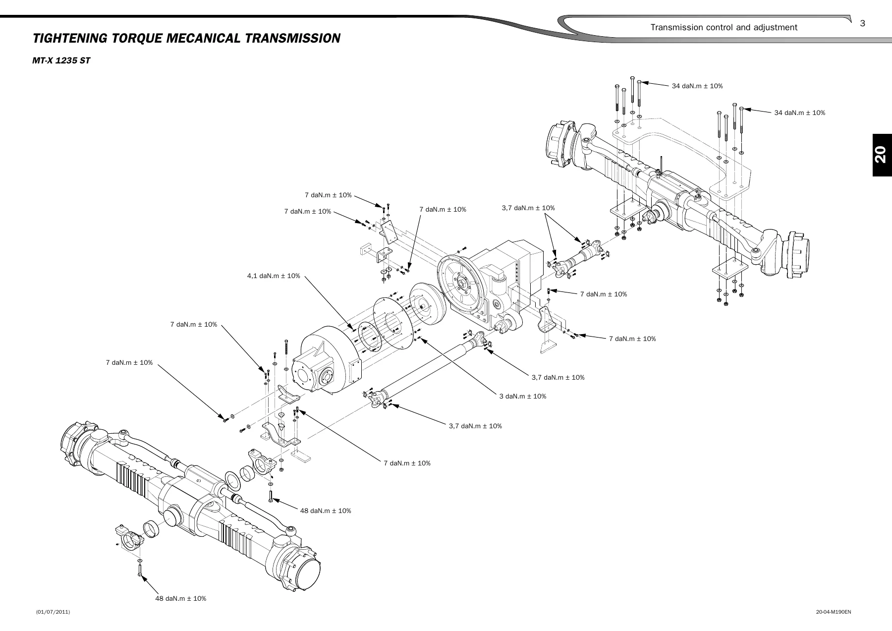
Across those chapters the manual supplies the standard tightening torque table to French Standard NF E25-030, used wherever a procedure does not state its own figure, followed by dedicated torque diagrams for the transmission and axle assemblies of the MT-X 1235, MT-X 1440 SLT and MT-X 1740 SLT. The brake chapter gives the service brake pedal height and free play adjustment, the transmission cut-off switch position, and the parking brake cable setting, while also opening up the negative hydraulic parking brake inside the axle with a labelled cross-section of the piston, Belleville washer and disc stack. The boom chapter is the deepest part of the document, taking you through removal and refitting of the lower, intermediate and upper hose groups, the correct flat placement of twin hoses, the bracket spacing measurements along the hose guide, and the extraction of the inner and outer telescopic cylinders and the tilt cylinder with a sling. Arm pad replacement is covered for the base of the arm, all three telescopes and the pad shims, including the clearance tolerance to work to after wedging.
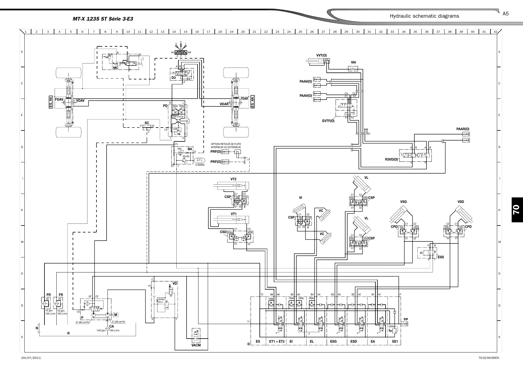
The hydraulic and electrical chapters are split by model, so the MT-X 1235 ST Serie 3-E3, the MT-X 1440 SLT Serie 4-E3 and the MT-X 1740 SLT Serie 3-E3 each receive their own schematic diagram plus a keyed component list showing the feed block, counterbalance valves, steering valve positions, stabilizer safety electrovalve, telescoping sections and attachment plugs. Special tooling lists are provided for the hydraulic brake bleeder, the base and digital manometer boxes, and the complete Manitou diagnostic kit with its VCI interface and cables.
What This Manual Supports
Because the MT-X 1235 1440 1740 Repair Manual covers the whole machine rather than one system, it supports the jobs that actually keep a telehandler working: engine control and adjustment on the Perkins 1104D, transmission and axle control settings, service and parking brake adjustment, boom hose replacement with the correct hose routing and bracket positions, telescopic and tilt cylinder removal, arm pad renewal, and hydraulic and electrical fault finding against the model-specific schematics. The torque tables and component keys let you tighten to the right figure and identify the right valve or plug before you touch it, which is what separates a repair that holds from one that comes back.
Put the Manitou MT-X 1235 1440 1740 Repair Manual to Work
IMAGES PREVIEW
This repair manual enables the full range of maintenance, repair and diagnostic work on the MT-X 1235 ST, MT-X 1740 SLT and MT-X 1440 SLT telehandlers – engine servicing, transmission and axle adjustment, brake overhaul, boom and cylinder work, hydraulic circuit testing and electrical troubleshooting. Working from the correct procedures and the manufacturer’s own specifications matters, because a telehandler boom, brake circuit and hydraulic system are unforgiving of guesswork; the wrong torque, the wrong hose routing or the wrong adjustment value can lead to damage, downtime or an unsafe machine. Delivered as an instant PDF download with no shipping and no waiting, the file opens on any computer, tablet or phone and every page can be printed for use in the workshop.
Reviews
There are no reviews yet.