
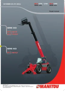
Manitou MT 1440 MT 1840 Telehandler Repair Manual 547963EN
Original price was: $39.95.$23.95Current price is: $23.95.
Repair manual for Manitou MT 1440 and MT 1840 telehandler families, with illustrated procedures covering engine installation and adjustment, transmission circuits and pressure checks, service and parking brakes, and MT 14/MT 18 telescopic boom systems. Document 547963EN, English, 1019 pages in PDF format.
Description
Manitou MT 1440 MT 1840 Telehandler Repair Manual 547963EN
The Manitou MT 1440 MT 1840 Telehandler Repair Manual 547963EN is a comprehensive 1019-page technical reference covering mechanical, transmission, braking, and telescopic-boom service operations for the MT 14 and MT 18 telehandler ranges. It includes machine and component illustrations, workshop photographs, hydraulic and transmission circuit diagrams, pressure information, adjustment data, dismantling sequences, and refitting procedures.
File Details
- Manual type: Repair Manual
- Brand: Manitou
- Primary model families: MT 1440 / MT 1840
- Document number: 547963EN
- Language: English
- Pages: 1019
- File format: PDF
Model and System Coverage
This Manitou MT 1440 and MT 1840 repair manual goes beyond component locations, focusing on actual service work including removal, refitting, adjustment, pressure checking, and system sequencing. The boom section distinguishes between the Triplex MT 14-meter arrangement and the Quadruplex MT 18-meter arrangement.
The Triplex boom coverage identifies machines including MT 1436 R, MT 1440, MT 1440 EP, and MT 1440 A, while the Quadruplex section identifies MT 1840 R, MT 1840, MT 1840 EP, and MT 1840 A.
Engine-related pages show component locations and procedures around the alternator, starter, fuel pump/filter, turbocharger, and accelerator control. Detailed engine/gearbox assembly removal and refitting are included.
Transmission material includes standard and inching circuit diagrams for neutral, forward, and reverse operation, component locations, pressure-port identification, pressure values, and specific tooling.
Brake coverage includes service-brake and parking-brake characteristics, adjustment, pressure testing, bleeding, towing preparation, and removal of the parking-brake components.
The boom material explains component coding, electrical harness routing, and the operating sequence of the QX four-component telescopic boom.
Chapters Covered
- General
- General instructions and safety notice
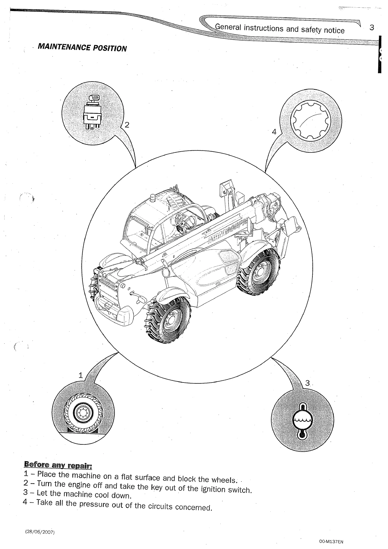
- Maintenance position and maintenance rules
- Engine
- Engine components location
- Cooling circuit locations
- Engine control and adjustment
- Alternator belt replacement and adjustment
- Alternator replacement
- Starter replacement
- Pump and fuel filter replacement
- Turbocharger replacement
- Accelerator pedal and position sensor adjustment
- Engine box assembly removal
- Engine compartment, air filter and exhaust removal
- Cooler and battery compartment removal
- Transmission universal joints
- Engine surroundings and connections
- Engine/gearbox assembly removal and uncoupling
- Engine box assembly refit
- Engine/gearbox coupling and converter installation
- Engine surroundings and harness reconnection
- Cooler, exhaust, air filter and engine box refitting
- Verification and test
- Transmission
- Transmission diagrams
- Standard neutral, forward and reverse gear circuits
- Inching neutral, forward and reverse gear circuits
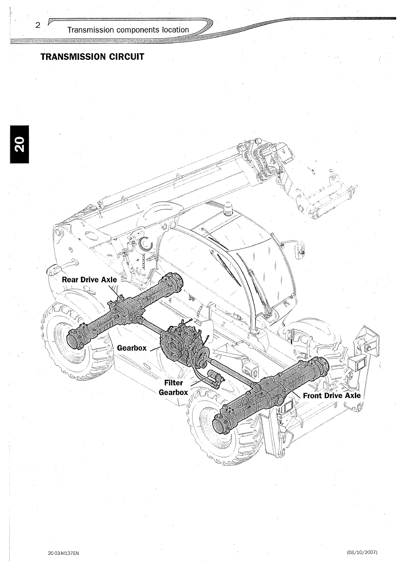
- Transmission components location
- Transmission and cooling circuits
- Transmission control and adjustment
- Pressure-port locations and values
- 4th gear locking
- Specific transmission tooling
- Axle
- Axle section references for characteristics, control, troubleshooting and tooling
- Brake
- Brake characteristics and specifications
- Service brake
- Parking brake
- Brake control and adjustment
- Service-brake pedal stop adjustment
- Service-brake pressure ports
- Service-brake bleeding procedure
- Parking-brake adjustment
- Parking-brake pressure port
- Parking-brake bleeding procedure
- Freewheel and towing procedure
- Parking-brake removal
- Brake pads and negative brake block
- Specific brake tooling
- Hydraulic brake bleed valve
- Parking brake bleed harness
- Boom
- Boom characteristics and specifications
- Triplex MT 14-meter boom
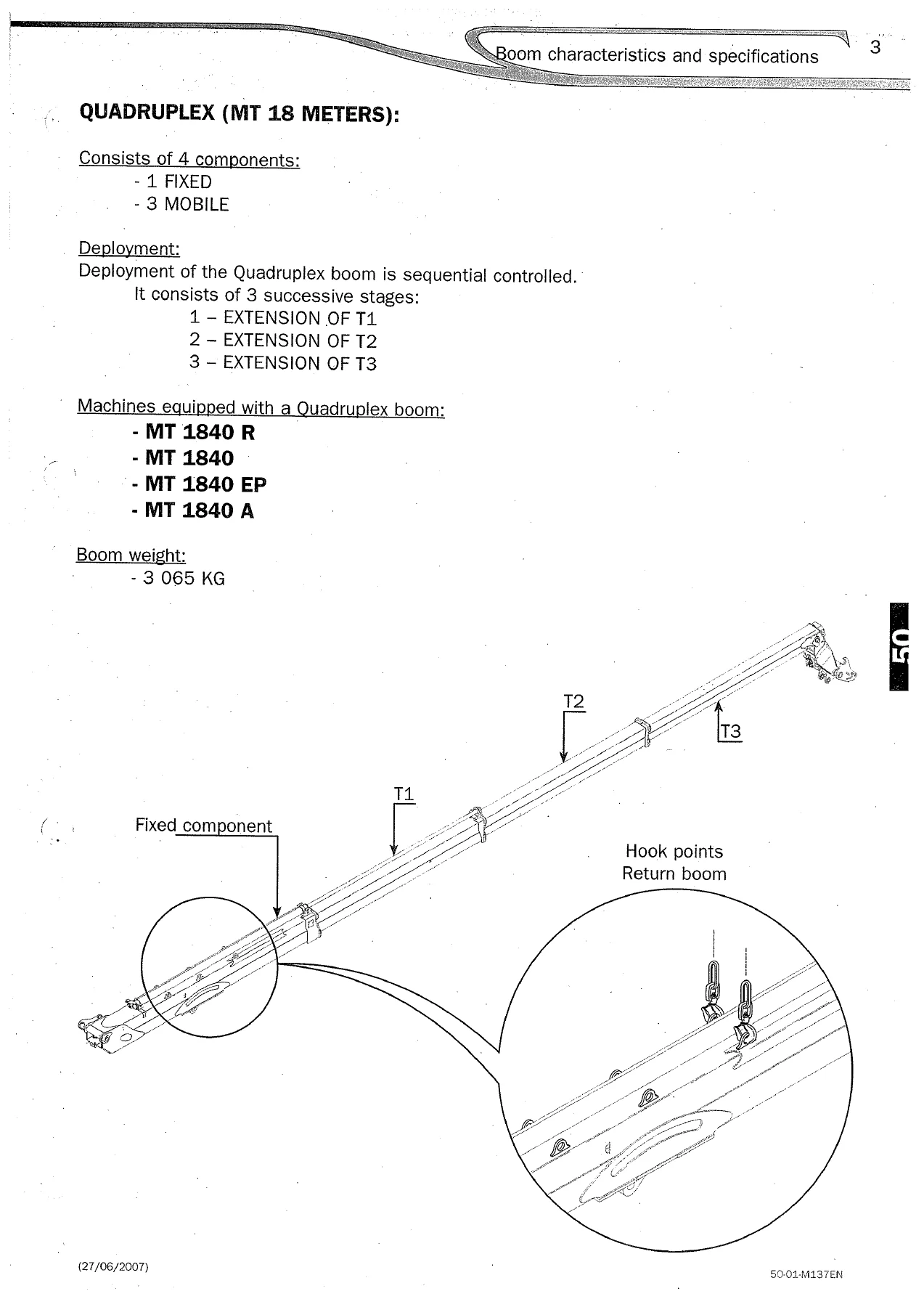
- Quadruplex MT 18-meter boom
- Boom components location
- TX and QX component codes
- QX boom control and adjustment
- QX boom sequencing principle
- Sensor and function-block locations
- Telescopic extension stages
- Telescopic retraction stages
- Hydraulic and electrical routing diagrams
Taken together, these sections provide a workshop-oriented view of how the covered Manitou telehandler systems are arranged, disconnected, adjusted, checked and reassembled. Illustrations identify individual components and connections, while the step-by-step pages provide the order of work for substantial jobs such as extracting and reinstalling the engine/gearbox assembly.
Engine and Powertrain Service Procedures
A substantial portion of the Manitou MT 1440 MT 1840 Telehandler Repair Manual 547963EN is devoted to access around the engine and gearbox. The manual illustrates the I.C. engine installation and identifies items such as the air filter, fuel pump and filter, starter, oil filter, injection pump, turbocharger, and alternator.
Procedures cover replacement of the alternator belt, alternator, starter, fuel pump/filter, and turbocharger, along with adjustment of the alternator belt and accelerator pedal position sensor.
The engine-box removal and refitting chapters are particularly detailed. They work through the engine compartment, air filter, exhaust system, cooler, battery compartment, front and rear transmission universal joints, hoses, harnesses, cables, and surrounding connections before the engine/gearbox assembly is lifted from the truck.
Reassembly includes engine-to-gearbox coupling, torque-converter positioning, mounting, reconnection of hydraulic and electrical systems, cooler installation, exhaust and air-filter refitting, and a final verification and test procedure. The manual also specifies lifting equipment for this operation, including a lifting system with a 1000 kg minimum capacity.
Transmission Circuits, Pressure Checks and Tooling
The transmission section gives visual circuit diagrams for both standard and inching configurations. Separate diagrams show neutral, forward, and reverse gear conditions so the technician can trace return, converter-pressure, and adjusted-pressure paths.
Component-location illustrations identify the gearbox, filter, front drive axle, rear drive axle, and cooling arrangement on the machine.
Transmission control pages identify individual pressure ports and provide a table of gearbox pressure-port values for main pressure, lubrication pressure, converter inlet pressure, and forward/reverse clutch outlet pressure.
The section also covers 4th gear locking and includes a drawing for a machined 50 socket used when dismantling the flanges connecting the transmission shaft to the gearbox.
Brake Adjustment, Bleeding and Parking Brake Work
The braking chapters combine specifications with workshop procedures. Service-brake information includes the pedal mechanism, braking arrangement, and oil-bath brake-disc data.
Parking-brake pages illustrate the negative brake unit and its disc arrangement. Control and adjustment procedures include brake-pedal stop setting, pressure-port locations, hydraulic diagrams, and brake bleeding.
The manual also explains parking-brake adjustment, hydraulic pressure testing, the parking-brake bleed procedure, and the steps required to freewheel and tow the truck.
That towing section includes an explicit warning to tow carefully without operating the parking brakes and states a maximum towing speed and distance within the procedure.
Parking-brake removal pages then show access to the brake pads and negative brake block. Dedicated brake-tool pages identify a hydraulic brake bleed valve assembly and parking-brake bleed harness.
MT 14 Triplex and MT 18 Quadruplex Boom Information
The boom section separates the MT 14-meter Triplex design from the MT 18-meter Quadruplex design. The Triplex arrangement is shown as one fixed and two mobile components with simultaneous deployment, while the Quadruplex arrangement uses one fixed and three mobile components with sequential extension.
IMAGES PREVIEW
The manual identifies a boom weight of 2710 kg for the Triplex configuration and 3065 kg for the Quadruplex configuration.
For the QX boom, detailed illustrations map the telescopic cylinders, function blocks, position sensors, inductive sensors, electrical connectors, and harness routing.
The sequencing chapter explains how extension and retraction occur through stages involving telescopes T1, T2, and T3, cylinders VT1, VT2, and VT3, function blocks BF1/BF123/BF23, and the associated electrovalves and sensor conditions.
Hydraulic schematics accompany the operating stages, making this part of the Manitou MT 1440 MT 1840 telehandler repair manual useful when tracing how a boom movement is commanded and sequenced.
Important Coverage Note
This PDF contains the repair sections reproduced in document 547963EN, but some index entries explicitly direct the technician to other repair-manual numbers or to separate hydraulic/electricity groups for additional characteristics, specifications, diagrams, or procedures. It should therefore be treated as the repair volume represented by these 1019 pages rather than as a replacement for every referenced Manitou manual or every system-specific publication.
Repair with the Procedures, Diagrams and Data in Front of You
The Manitou MT 1440 MT 1840 Telehandler Repair Manual 547963EN supports practical workshop jobs ranging from engine-component replacement and engine/gearbox removal to transmission pressure diagnosis, brake adjustment and bleeding, parking-brake servicing, and telescopic-boom system tracing.
Using the illustrated sequences, component locations, pressure information, and adjustment data helps keep repairs aligned with the procedures and values documented for the covered machines instead of relying on memory or trial and error.
Delivered as an instant PDF after purchase, there is no physical book and no shipping delay. Open the manual on a computer, tablet, or phone whenever workshop access is needed, and print the pages you want for use beside the machine.

Reviews
There are no reviews yet.