
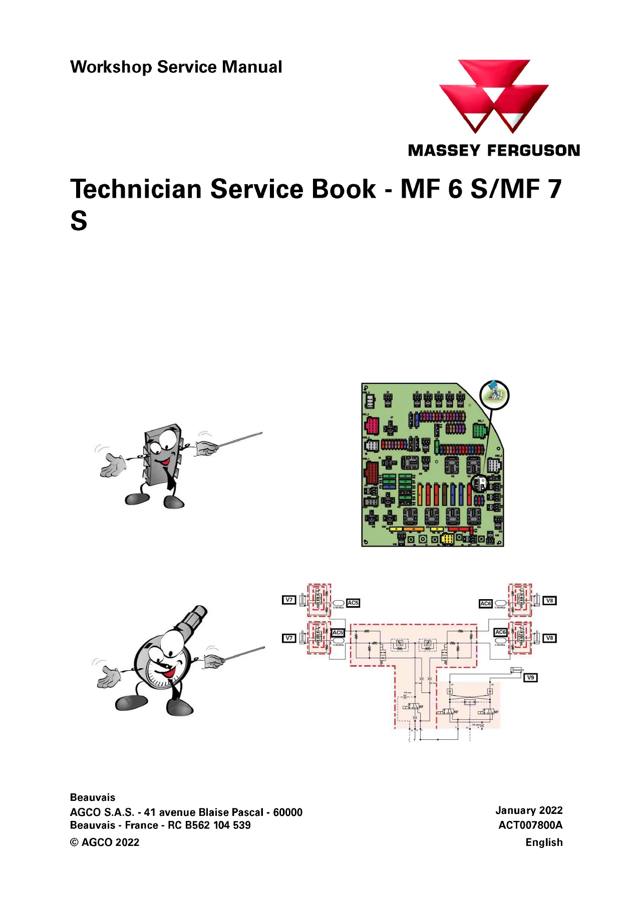
Massey Ferguson MF 6S & MF 7S Technician Service Book PDF – Dyna-6 Dyna-VT Tractor Workshop Manual
Original price was: $79.95.$49.95Current price is: $49.95.
Complete 825-page Massey Ferguson MF 6S / MF 7S Technician Service Book in PDF. Covers Dyna-6, Dyna-7T and Dyna-VT transmissions, AGCO Power Stage V and Tier 2/Stage II engines, fault codes, wiring, hydraulics, capacities, tightening torques and step-by-step calibration procedures.
Description
Massey Ferguson MF 6S & MF 7S Technician Service Book – PDF Workshop Manual
This Massey Ferguson MF 6S / MF 7S Technician Service Book is the full workshop reference file for the MF 6S and MF 7S tractor ranges, delivered as a single 825-page PDF. It is the document technicians reach for when they need AGCO Power engine data, Dyna-6 and Dyna-VT transmission procedures, hydraulic and electrical schematics, fault-code lookup tables, fuse assignments, calibration routines and tightening torques – all in one file rather than split across separate booklets. Whether you are diagnosing an armrest fault code, calibrating a Dyna-VT transmission, bleeding the trailer brake circuit or chasing a broken wire on the CAN network, the answer is inside this service book.
The manual is written for the MF 6S.135, 6S.145, 6S.155, 6S.165 and 6S.180 alongside the MF 7S.145, 7S.155, 7S.165, 7S.180, 7S.190 and 7S.210 – covering both Dyna-6 and Dyna-VT variants, and both the Stage V and Tier 2/Stage II AGCO Power engine families. It is organised the way a dealer technician actually works: locate the system, read the fault code table, follow the diagram, apply the specified torque, then run the calibration.
File Details
- Manual type: Technician Service Book
- Brand: Massey Ferguson (AGCO)
- Model series: MF 6S / MF 7S
- Transmissions covered: Dyna-6, Dyna-7T, Dyna-VT
- Engine families: AGCO Power 49 LFTN-D5, 66 LFTN-D5, 66 LFEN-A2 (Stage V and Tier 2 / Stage II)
- Language: English
- Format: PDF
- Page count: 825
- Publisher: AGCO Corporation
Chapters Covered
- Foreword
- General information
- Technical data
- General specifications Dyna-6 and Dyna-7T
- Model-specific specifications (6S.135 through 7S.210)
- Capacities
- Tightening torques
- Retaining compounds and sealing products
- Tech Connect Diagnostics
- Fault codes and fault tables
- Fuse box descriptions
- Electrical diagrams
- Hydraulic diagrams
- Pneumatic diagrams
- Adjustments, bleeding and calibrations
Model Specifications and Technical Data
Each model in the MF 6S and MF 7S line has its own specification block covering the engine, transmission type, rear axle, final drive, PTO speeds, front axle, hydraulic system and electronics. The 4-cylinder models (6S.135, 6S.145, 6S.155, 6S.165, 6S.180) run the AGCO Power 49 LFTN-D5 engine, while the 6-cylinder models (7S.155 through 7S.210) use either the 66 LFTN-D5 or 66 LFEN-A2 depending on emission level. Hydraulic system data is broken down by configuration – Open Center and Closed Center, Essential, Efficient and Exclusive versions – with flow rates and spool valve limits listed for each. Front axle types include the DANA 735, 740, 750 and the suspended variants, and the synchronised ratio for each is stated exactly as it appears on the name plate.
Capacities and Tightening Torques
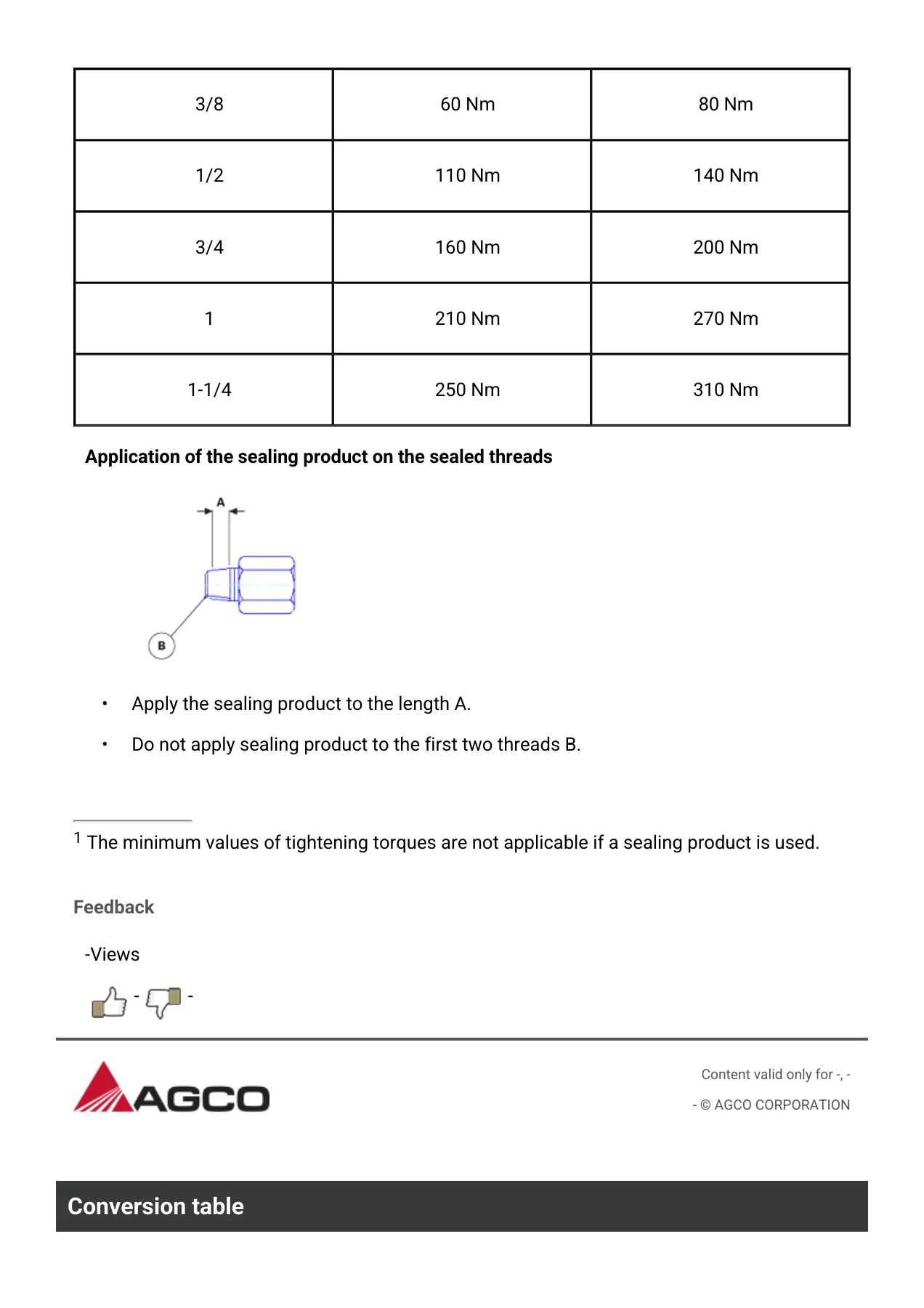
The capacities chapter covers fuel tanks (Stage V and Tier 2/Stage II), DEF tanks, cooling systems, oil sumps, rear axle/transmission volumes, front axle beam and final drive volumes, refrigerant R134A charge, front PTO oil, windshield washer reservoir and pneumatic brake antifreeze. The torque chapter contains the full metric and inch fastening tables split by tensile grade – ISO 4.6, ISO 8.8, ISO 10.9 – plus the reduced-torque tables for phosphated or zinc-flake-coated threads. A separate hydraulic union torque section covers 37° flare, EO2, metric straight thread, inch straight thread and steel sealed-thread fittings, and includes the correct method for applying thread sealant without contaminating the first two threads.
Tech Connect Diagnostics and Fault Codes
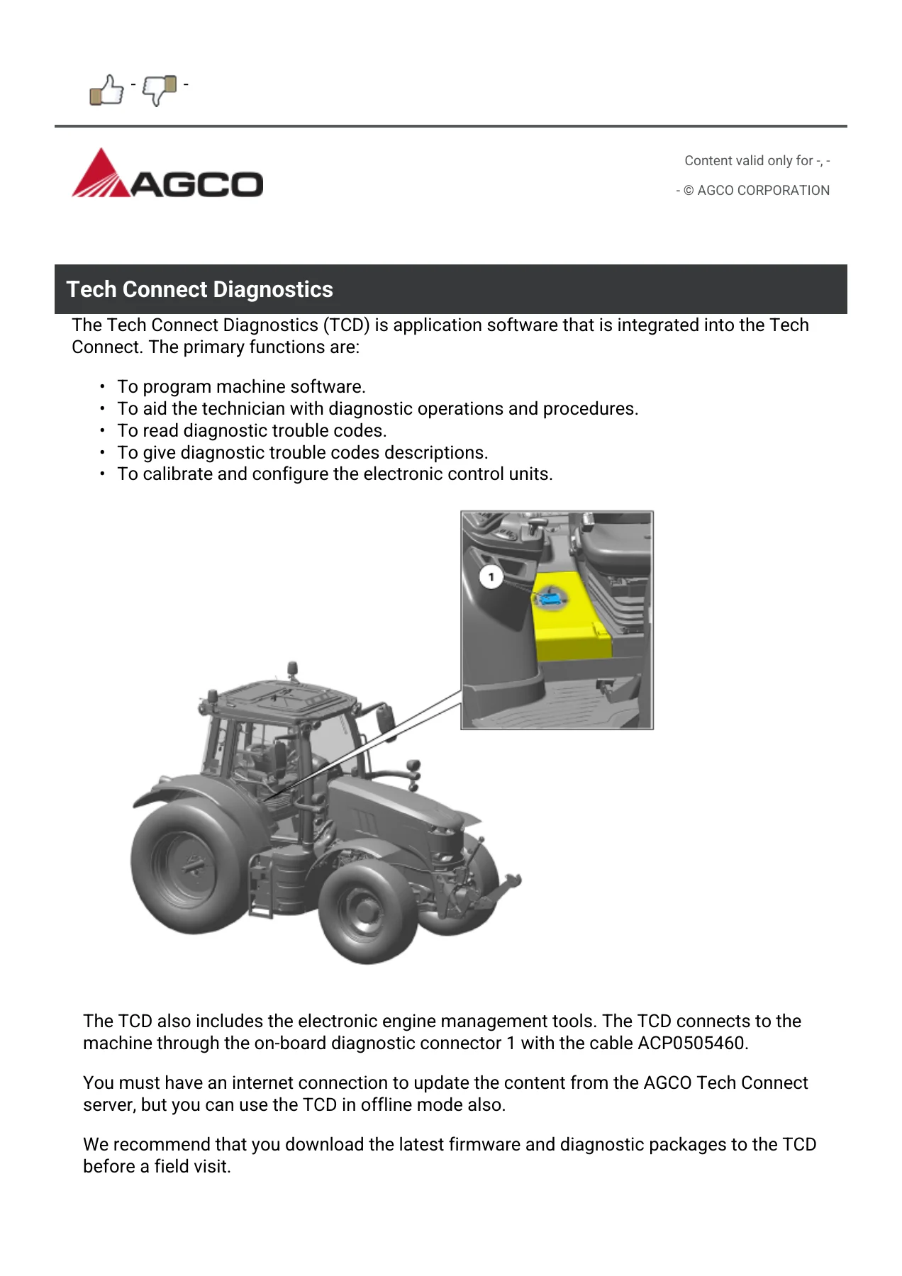
Tech Connect Diagnostics (TCD) is documented with the connection point, cable reference and the primary functions – machine software programming, guided diagnostic procedures, reading and describing trouble codes, and ECU calibration/configuration. The fault-code library is the biggest single block of the manual and is organised system by system: ARM (armrest), AV01 through AV09 (auxiliary spool valves), BRAKE, CABSUSP / CAB_SUSP, CEAG (CEA Guide / Auto-Guide), DASH, DGW (diagnostic gateway), DIFF, DRIVE, ENG (AGCO Power engine), FAXLE, FHITCH, FPTO, HPBRAKE, HVAC, HYD, ISO, JOY, KEYBOARD, MPAD, PVED (steering valve), RHITCH, RHS, RPTO, SC, SRCM, TELE, TRANS and TRANS_CVT. Each fault table gives the fault code, affected component, cause and the consequence with the recommended remedy – so you can trace a code back to a solenoid, a sensor, a wiring short or an ECU before you touch a spanner.
Fuse Boxes, Electrical, Hydraulic and Pneumatic Diagrams
The manual covers the main fuse box (right console), the secondary fuse box (above the battery housing) and the additional fuses and relays for panoramic cab variants, with fuse number, capacity, dimension and the specific system each one protects. The electrical diagram index runs the full EFD range – battery power points and earth points, 4WD, differential lock, PowerShuttle, rear and front PTO, transmission power supply, suspended cab, HVAC, wipers, lighting modules, Datatronic 5, Isobus, Auto-Guide and trailer connectors. Hydraulic diagram indexes cover the auxiliary hydraulics for ML140 and GTA2520 Load Sensing / Open Center 100 L/min, including Mother Regulation versions, plus the transmission hydraulics diagram. Pneumatic diagrams cover the ML140/ML180 and GPA20 Mother Regulation layouts. Cable colour identification tables for both FSEN04047 and FSEN04080 are included, so you can read every wire in the schematics.
Bleeding and Calibration Procedures
The adjustments, bleeding and calibrations section is where this book really earns its place in a workshop. Brake bleeding is documented separately for Dyna-6 and Dyna-VT, and the pneumatic trailer brake bleeding is covered for both transmissions with the colour-coded bleed screws (green right rear, blue left rear, red parking brake) and the exact pressure limits. Calibration procedures are then given one by one: instrument panel calibration screen access, rear PTO calibration, clutch pedal, throttle pedal sensor, forward travel lever sensor, FingerTIPs on the right-hand console, left/right and centring steering angle sensor (WAS), suspended front axle, Dyna-6 transmission, Dyna-6 power sensor, Dyna-VT high/low speed range (Hare/Tortoise), Dyna-VT transmission, Dyna-VT coupler function, rear linkage, front linkage, hydraulic steering unit and forward speed. Every calibration has its own error-code list so you know what Err 0255, Err 0004 or Err 0064 actually means and how to clear it.
Why This Technician Service Book Belongs on Your Bench
Modern Massey Ferguson tractors are software-heavy machines. A single failing sensor can leave an operator with a derated engine, a locked transmission or an intermittent fault that only appears under load. Chasing that fault without the correct fault-code table, wiring diagram and calibration routine is a guessing game that costs time and money – and often makes things worse. This manual gives you the exact sequence the factory technician follows: read the fault, test the circuit, verify the sensor, replace the component, then run the calibration that re-teaches the controller where the new part sits.
Because the entire MF 6S and MF 7S range shares a huge amount of its electronics, hydraulics and transmission architecture, this one PDF covers eleven distinct model variants and three transmission families. That means you are not buying a manual for one tractor – you are buying the whole platform reference.
IMAGES PREVIEW
Delivery is instant. Once payment is confirmed you receive the PDF immediately as a download, no shipping, no waiting for a courier. The file opens on any laptop, tablet, phone or workshop PC, and you can print the pages you actually need for the bench – a fault table, a torque list, a wiring diagram – without dragging the whole book into the workshop. Keep it on the shop computer and it will still be there the next time a code comes up.
Reviews
There are no reviews yet.