
Massey Ferguson MF35 MF50 MF135 MF150 Workshop Service Manual – Complete PDF Repair Guide
Original price was: $55.95.$34.95Current price is: $34.95.
The complete Massey Ferguson Workshop Service Manual covering MF35, MF50, MF135 and MF150 tractors. Includes front axle and steering, engine overhaul for Z-134, A3.152, AD3.152 and Z-145 power plants, dual and single clutches, 6-speed and 8-speed transmissions, Multi-Power, differential and rear axle, PTO, and the internal hydraulic system. Instant PDF download.
Description
Massey Ferguson MF35, MF50, MF135 & MF150 Workshop Service Manual
This is the full workshop service manual for the Massey Ferguson MF35, MF50, MF135 and MF150 tractors. It was written for the technician working on the bench and in the field, and it is the same body of information used to strip, inspect, rebuild and re-time these tractors from the front axle through to the rear axle and PTO. Every section assumes the reader is going to actually take the machine apart, so the text is written around removal sequences, measurement limits, reaming sizes, shim packs, torque values and gear timing marks rather than general description.
The manual opens with GROUP IV – SECTION A covering the front axle and steering, then moves through GROUP I for the engine, GROUP II for clutch, transmission, differential and PTO, and GROUP III for the internal hydraulic system. Later sections extend coverage to the MF65, MF165 and MF175 where the same components and assemblies are shared with the 35, 50, 135 and 150 chassis.
File Details
- Manual type: Workshop Service Manual
- Brand: Massey Ferguson
- Models covered: MF35, MF50, MF135, MF150 (plus MF65, MF165, MF175 and MF180 coverage in the shared system sections)
- Document numbers: 1448811M1 (MF35/50), 1448813M1 (MF135/150)
- Language: English
- File format: PDF
Chapters Covered
- Front Axle and Steering
- Engine (Gas and Diesel)
- Dual Clutch and Single Clutch
- Transmission
- Multi-Power Transmission
- Differential, Pinion and Rear Axle
- Power Take-Off and Belt Pulley
- Internal Hydraulic System
- Electrical System
Front Axle and Steering
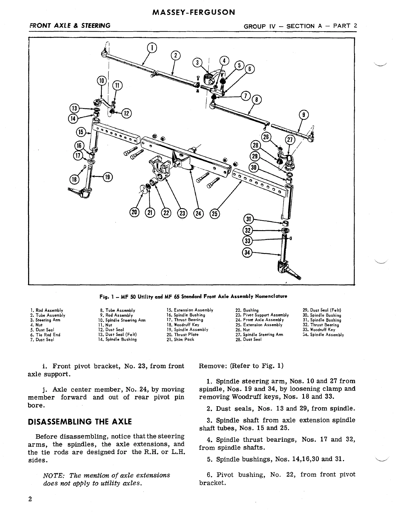
Part 1 opens with the standard and heavy-duty utility front axle used on the 35, and walks through removing the front axle and support assembly, disassembling the axle extensions, inspecting the spindle and pivot bushings, and reaming replacement bushings to size. Specific service limits are given — extension assembly bushing clearance of 0.0035 to 0.005 inch, pivot bushing replacement above 1.790 inch diameter, pivot pin replacement below 1.700 inch. The MF50 and MF65 wide front axle section follows with the same level of detail: removing the axle as a unit, disassembling spindle steering arms with Woodruff keys, measuring the front pivot pin at 1.999 to 2.001 inch outside diameter, and shim-pack end-play adjustment between the support housing and front pivot bracket at 0.002 to 0.008 inch. Single wheel and twin wheel row crop front axles are covered with their own removal and inspection sequences, including the needle bearing and thrust bearing arrangements in the single wheel fork. Steering gear housing sections cover the screw and recirculating ball-nut type gear with two pinion shafts, the manual steering gear disassembly and reassembly, pre-load adjustment, and the power steering variant with its control valve, plunger and spring packs, and the steering gear housing used on the MF50 and MF65.
Engine
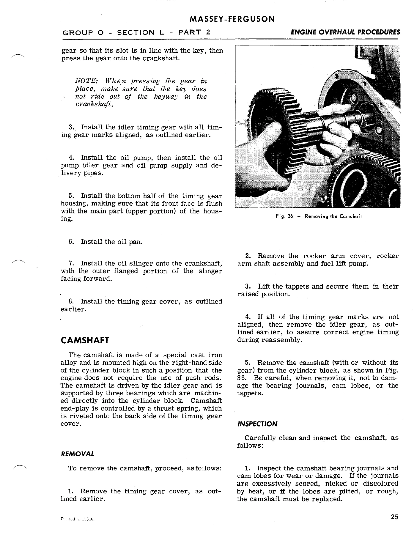
Four engine families are covered in detail: the Continental Z-134 four-cylinder gasoline engine, the Perkins A3.152 three-cylinder diesel, the Perkins AD3.152 three-cylinder diesel, and the Continental Z-145 four-cylinder gasoline engine. Each has its own general specifications, torque tensions and rebuilding specifications section, followed by overhaul procedures. The Z-134 chapter gives bore and stroke, compression pressure tables by altitude, piston and sleeve fits, ring side clearance and ring gap, connecting rod bushing dimensions, crankshaft journal diameters, main bearing clearances, timing gear backlash, camshaft journal and lobe data, valve tappet clearances, valve guide dimensions and valve seat angles. Engine removal from the tractor is given step by step — draining the cooling system, disconnecting the choke rod, air cleaner pipe, fuel line, generator, coil and tractor-meter cable, then lifting the engine out on a hoist. Rocker arm shaft assembly servicing covers shaft diameter measurement, rocker bushing inside diameter measurement and push rod inspection, followed by cylinder head removal, valve removal, valve refacing to 30 degrees intake and 44 degrees exhaust, valve guide replacement with special tools, valve seat insert replacement with 0.010 inch oversize inserts and a 0.003 inch interference fit, and cylinder head tightening sequences with torque values. Piston and connecting rod assemblies, sleeve projection above the block, connecting rod numbering and oil spray hole orientation, crankshaft removal, main bearing replacement with the engine installed, rear oil seal installation, camshaft removal, timing gear backlash and timing gear cover procedures are all laid out. The AD3.152 diesel chapters mirror this structure with the added detail of the CAV distributor type injection pump, fuel injector nozzle opening pressures, cylinder liner installation with interference fit, balance weight retaining setscrews, and the rear crankshaft oil seal rope type retainer with its 0.010 to 0.020 inch joint face projection.
Clutches
The dual clutch chapter covers the forward and rearward pressure plate arrangement, the twelve coil springs in the primary cover and the Belleville spring in the secondary, the false flywheel ring, and the release lever height adjustment using special gauges. Secondary pressure plate clearance is called out at 0.090 ± 0.002 inch for the 35, 50 and 65 tractors, with the red and blue painted Belleville springs identified for the different models. Disassembly and reassembly steps include unhooking release lever torsion springs, driving out upper and lower pivot pins, replacing the retainer pins, hooking the torsion springs back into the cover recesses, and tightening the “T” bolts evenly to compress the coil springs to solid height. The single clutch chapter covers the agricultural and industrial type pressure plate for the 35, 50 and 202, with spring free length and load checks and release lever adjustment using gauge OTC-FT-359.
Transmission
The 35, 50 and 65 transmission assembly is covered from removal through disassembly and reassembly: detent springs and pins, planetary shifter fork and coupler, shifter rails and forks, live PTO shaft, main drive shaft retainer, countershaft and drive gears, and the planetary gear assembly with its 56 loose needle bearings in the reverse gear cluster. The Multi-Power transmission chapter adds the hydraulically actuated clutch on the input shaft, the over-running clutch on the countershaft, the control valve on the input shaft retainer, and the oil flow paths that shift between standard drive and overdrive. The 8-speed transmission chapter covers the sliding gear set compounded by the dual-range planetary, the reverse idler with loose needle bearings, the countershaft front and rear bearings, and the snap ring positions that must be staged in the right grooves during reassembly. The standard 6-speed transmission chapter covers the dual clutch version with its PTO input shaft, retainer housing, and reverse idler installation using special tool MFN 800K.
Differential, Pinion and Rear Axle
The differential, pinion and rear axle chapter covers the early 35, 50, 202 and 204 assembly, including the change from 7/16 inch to 1/2 inch axle trumpet studs and the increase from six to twelve bearing retainer studs. Rear axle end-play is specified at 0.002 to 0.008 inch, adjusted with shims. The differential carrier bearing pre-load adjustment is done with a special tool and a bearing shield or shim chart. The drive pinion assembly, straddle-mounted with two tapered roller bearings at the front and a roller pilot bearing at the rear, is covered with bearing pre-load set to 18 to 22 in.-lbs. of rolling torque. Ring gear and pinion backlash is called out at 0.005 to 0.015 inch and adjusted with shims between the ring gear and differential case half. The differential lock mechanism used on later tractors is covered with its coupler, shift fork, shoes, cam and shaft assembly, and pedal adjustment of 1/4 to 1/2 inch clearance above the step plate.
Power Take-Off and Belt Pulley
The PTO chapter covers the output shaft assembly, ground speed PTO drive gears, front output shaft support, and the three different shaft extension lengths used on the 35, 50 and 65 tractors. Live PTO and proportional ground speed operation are explained, with the shaft speed related to rear wheel travel at approximately one revolution per 19 inches. The belt pulley chapter covers the 35 and 50 belt pulley and the MF65 light-duty and heavy-duty belt pulleys, including the driven pulley diameter selection table, bearing and seal replacement, and gear backlash adjustment of 0.004 to 0.006 inch on the bevel gears.
Internal Hydraulic System
The internal hydraulic system for the 35, 50 and 65 tractors covers the scotch yoke piston type pump, the lift cover with its ram cylinder and piston, the master control spring, the control valve and oscillator, the dash pot, and the response control linkage. Pressure relief valve identification is given with the shoulder marking the 2,500 psi valve. The four-cylinder pump is disassembled and reassembled with cam blocks, pistons, valve chambers, and valve seat reseating tool N-6007. A separate section covers the internal hydraulic system for the MF135, 150 and 165 with the pump mounted in the center housing, the multi-power pump drive gear backlash of 0.002 to 0.005 inch, and the response control adjustment with a 3/32 inch Allen setscrew.
Electrical System
The electrical system sections list the battery, generator, starting motor and voltage regulator specifications for the various engine applications. Generator part numbers, rotation, brush spring tension, field current, and cold output readings are given, along with starting motor pinion clearance, no-load test values and resistance test values. Regulator air gap, point opening and voltage settings are covered with a temperature-voltage chart.
Why This Workshop Service Manual Matters
The Massey Ferguson MF35, MF50, MF135 and MF150 are still working tractors, and the information in this manual is what separates a correct repair from a guess. Torque values, bearing clearances, bushing reaming sizes, shim pack thicknesses, gear timing marks, pre-load rolling torque figures and seal installation depths are all specified. The manual tells you which special tools are required — OTC-FT-52, OTC-FT-53, OTC-FT-54 for valve guides, MFN 8308 for cylinder liners, FT 358 for the master control spring retaining nut, N-6007 for hydraulic valve seats — and where to use them.
Whether you are rebuilding a Z-134 gasoline engine, replacing the clutches in a dual clutch 35 or 50, adjusting the Multi-Power control linkage, setting the differential carrier bearing pre-load, reseating the hydraulic pump valve seats, or correcting front axle toe-in to 0 to 1/4 inch, the procedure and the numbers are here.
IMAGES PREVIEW
Instant PDF Delivery
This Massey Ferguson workshop service manual is delivered as an instant PDF download after payment. There is no shipping, no waiting for a physical book, and no risk of a lost package. The file can be opened on a workshop laptop, a tablet on the bench, or a phone in the field, and any page can be printed for use beside the machine. Keep the PDF on hand and you have the complete MF35, MF50, MF135 and MF150 service information ready whenever the next job comes in.

Reviews
There are no reviews yet.