
Mercury 30 HP & 40 HP Outboard Service Manual – 1997 Two-Stroke Repair Guide (PDF)
Original price was: $44.95.$29.95Current price is: $29.95.
Complete Mercury 30 HP and 40 HP two-stroke outboard service manual. 332-page PDF covering ignition, fuel system, powerhead, mid-section, lower unit, and manual starter. Instant download.
Description
Mercury 30 HP & 40 HP Outboard Service Manual — Complete 1997 Two-Stroke Repair Guide
This is the complete Mercury Marine service manual for the 30 HP and 40 HP two-cylinder, two-stroke outboard motors. Published in March 1997 as document number 90-826148R2, this 332-page PDF covers every major system on these engines — from ignition and fuel delivery through to the gear housing, mid-section, and rewind starter. Whether you are rebuilding a powerhead, diagnosing an electrical fault, servicing the lower unit, or performing routine maintenance, this manual provides the procedures, specifications, and illustrations needed to complete the job correctly.
File Details
- Manual Type: Service Manual
- Brand: Mercury Marine
- Models Covered: 30 HP, 40 HP (2-Cylinder, 2-Stroke)
- Language: English
- Page Count: 332
- File Format: PDF
- Publication Number: 90-826148R2
- Publication Date: March 1997
Chapters Covered
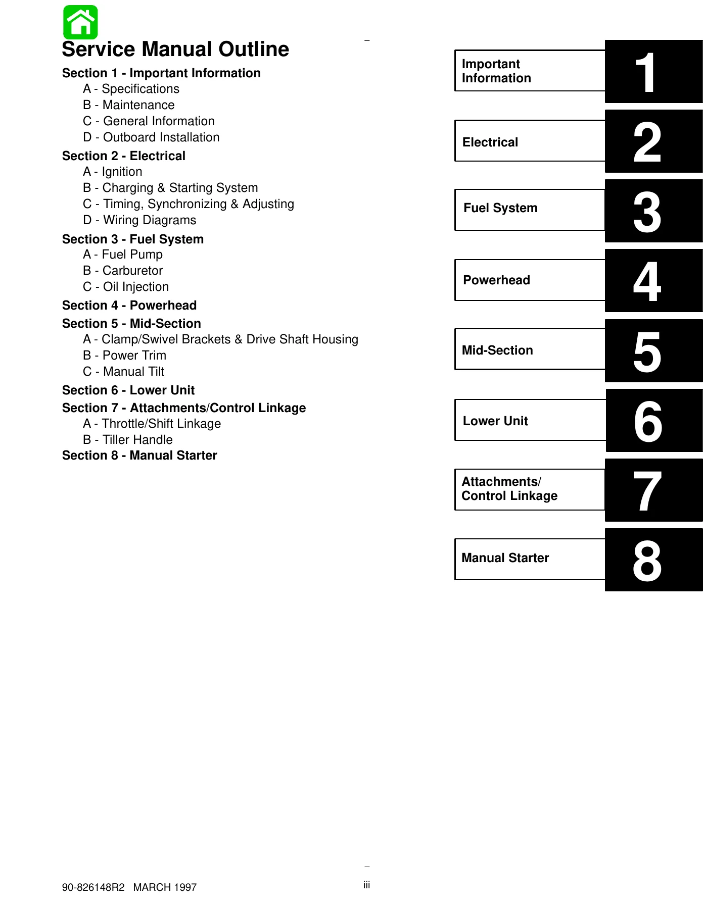
- Section 1 — Important Information
- Section 2 — Electrical
- Section 3 — Fuel System
- Section 4 — Powerhead
- Section 5 — Mid-Section
- Section 6 — Lower Unit
- Section 7 — Attachments/Control Linkage
- Section 8 — Manual Starter
Section 1 — Important Information
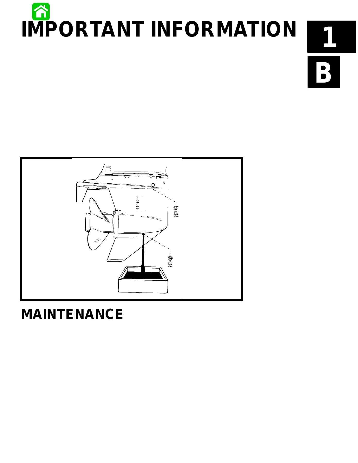
Safety alerts, maintenance schedules, general service information, and outboard installation procedures. The general specifications tables cover cylinder block dimensions, piston and ring clearances, crankshaft tolerances, gear housing ratios and capacities, fuel system pressures, oil injection output, starting system amperage draws, charging system outputs, ignition timing, and carburetor settings. The maintenance schedule details tasks required before each use, after each use, every 100 hours or annually, every 300 hours or three years, and before storage — including lubrication points, gear case lubrication, propeller service, corrosion control anode inspection, fuel system checks, cooling system flushing, and storage preparation for the fuel system, external and internal components, gear case, and battery. The general information chapter covers serial number locations, weather effects on engine performance, boat weight distribution, hull design factors, trim operation, and the causes and prevention of detonation and cavitation.
Section 2 — Electrical
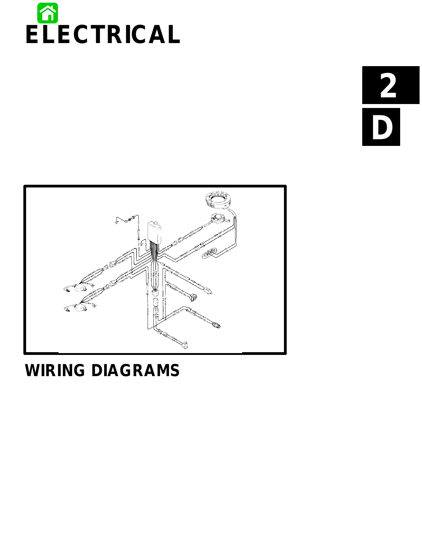
Complete ignition system coverage for both serial number ranges, including the capacitor discharge module (CDM), stator, trigger, timing protection module (TPM), and flywheel. Theory of operation sections explain capacitor charging, trigger circuits, ignition coil circuits, and stop circuits. Testing procedures include DVA tests for the stator, resistance tests for the TPM, stator, trigger, and CDM, plus ignition diagnostic procedures. The charging and starting system chapters cover battery testing and charging, specific gravity readings, electrolyte levels, winter storage, stator ohm tests, alternator system tests, rectifier tests, voltage regulator tests, and starter motor removal, disassembly, cleaning, inspection, testing, brush replacement, and reassembly. Timing, synchronizing, and adjusting procedures cover idle speed adjustment, idle mixture screw adjustment, maximum spark advance adjustment, shift link rod installation and adjustment, throttle cable installation and adjustment, and oil pump synchronization. Wiring diagrams cover manual start, electric start, tiller handle, power trim, charging systems, remote control, instrument wiring, gauge wiring, and synchronizer wiring.
Section 3 — Fuel System
Fuel pump theory of operation, troubleshooting, testing, and rebuild procedures for both manual and electric pumps. The carburetor chapter covers WME series carburetor specifications, jet orifice sizes, fuel system flow diagrams for manual start, electric start, and electric start tiller handle models, idle speed adjustment, idle mixture screw adjustment, float adjustment, main jet adjustment, rejetting for high altitude operation, and fuel system troubleshooting. The oil injection chapter covers the oil reservoir, oil pump, check valve vent, low oil sensor, timing and protection module, oil injection flow system, pump drive assembly, carburetor/oil pump synchronization, bleeding air from the system, and oil pump volume testing.
Section 4 — Powerhead
Cylinder block components, induction manifold, crankshaft, pistons, flywheel, torque sequences, powerhead removal, crankshaft disassembly and inspection, piston and connecting rod disassembly, connecting rod inspection, cylinder block and crankcase cover cleaning and inspection, cylinder bore honing, piston and piston ring inspection, check valve service, thermostat testing, reed block inspection, powerhead reassembly and installation, bleed hose routing, and break-in procedure. Specifications include cylinder bore dimensions, piston dimensions, ring end gaps, water pressure values, and poppet valve opening temperatures.
Section 5 — Mid-Section
Clamp bracket components, swivel tube components, swivel bracket components, drive shaft housing components, and drive shaft housing disassembly and reassembly. The power trim chapter covers power trim components, mounting, theory of operation, trimming characteristics, trailering, manual tilting, trim-in angle adjustment, complete flow diagrams for trim up, tilt up, maximum tilt, trim down, shock function up, shock function return, and manual tilt modes. Troubleshooting sections cover hydraulic system flow charts, power trim electrical system diagnostics, power trim removal, disassembly, cleaning, inspection, repair, trim motor electrical tests, reassembly, O-ring and seal placement, bleeding procedures, and system installation. The gas assist manual tilt chapter covers clamp bracket components, hydraulic assist adjustments, manual trim system removal, and installation.
Section 6 — Lower Unit
General service recommendations, bearing and seal inspection, gear housing components for both drive shaft and propeller shaft, draining and inspecting gear lubricant, propeller removal, gear housing removal, water pump seals, inspection of the upper drive shaft bearing, pinion gear bearing, pinion gear, forward gear, shift shaft, propeller shaft disassembly, propeller shaft and carrier inspection, clutch dog, cam follower, reverse gear, reverse gear bearing, bearing carrier, gear housing reassembly, shift shaft assembly, pinion bearing race, forward gear, pinion gear/drive shaft assembly, propeller shaft, bearing carrier, water pump, gear housing pressure test, gear housing installation, filling gear housing with lubricant, installing gear housing to drive shaft housing, trim tab adjustment and replacement, and propeller installation.
Section 7 — Attachments/Control Linkage
Throttle linkage components for serial numbers below and above 0G590000, bottom cowl and shift components, and tiller handle components. Adjustment procedures cover both the tiller handle model and the tiller handle model with mechanical spark advance.
Section 8 — Manual Starter
Manual start components, rewind starter disassembly, cleaning and inspection, reassembly, adjusting rewind spring tension, and starter interlock cable adjustment.
Models & Serial Number Coverage
This service manual covers the Mercury 30 HP and 40 HP two-cylinder, two-stroke outboard motors across the following serial number ranges:
- S/N 0G380074 & Below
- S/N 0G380075 Thru 0G589999
- S/N 0G590000 & Above
Model variants covered include the 30 HP, 40 HP, Sea Pro, Marathon, and EHO configurations. Electrical and ignition sections are organized by serial number range, so you can quickly identify the correct procedures and specifications for your specific engine.
Why This Mercury 30/40 HP Service Manual Matters
Working on a two-stroke outboard without the correct specifications and procedures is how expensive mistakes happen — incorrect torque values, improper ignition timing, wrong fuel mixture settings, or missed maintenance intervals can all lead to premature engine failure. This manual gives you the exact measurements, clearances, torque sequences, and step-by-step procedures that Mercury Marine published for these engines. The wiring diagrams alone are invaluable for diagnosing electrical faults, and the power trim flow diagrams make troubleshooting hydraulic problems straightforward.
IMAGES PREVIEW
Delivered as an instant PDF download, this manual works on any device — laptop, tablet, or smartphone — and every page is printable for use in the workshop. No shipping, no waiting. Whether you are a professional marine mechanic or a boat owner who prefers to handle maintenance and repairs yourself, this Mercury 30 HP outboard service manual provides the technical depth and accuracy you need to keep your engine running reliably.


Reviews
There are no reviews yet.