
MHIRJ CRJ700/900/1000 Aircraft Maintenance Manual Chapter 06 Dimensions and Areas
Original price was: $39.95.$24.95Current price is: $24.95.
Complete Chapter 06 Dimensions and Areas for the MHIRJ CRJ700, CRJ900, and CRJ1000 — aircraft dimensions, zones, fuselage/wing/empennage stations, and every access panel identification code. 870+ page PDF.
Description
This MHIRJ CRJ700/900/1000 Aircraft Maintenance Manual Chapter 06 Dimensions and Areas is the full dimensional and access reference for the CRJ700, CRJ900, and CRJ1000 regional jet family. Issued under document CSP B-001 – MASTER with ON A/C ALL effectivity, this chapter gives maintenance engineers, structures specialists, and technical libraries the dimensional framework and access-panel identification required to locate any structural area, component, or inspection point on the aircraft. Every fuselage, wing, empennage, nacelle, and landing gear reference plane is documented, together with the alphanumeric access codes that point to the exact door, panel, or fairing for a given task.
File Details
- Manual Type: Aircraft Maintenance Manual (AMM) — Chapter 06
- Brand: MHIRJ
- Models Covered: CRJ700, CRJ900, CRJ1000
- Language: English
- Page Count: Approximately 871 pages
- File Format: PDF
- Document Number: CSP B-001 – MASTER
- Effectivity: ON A/C ALL
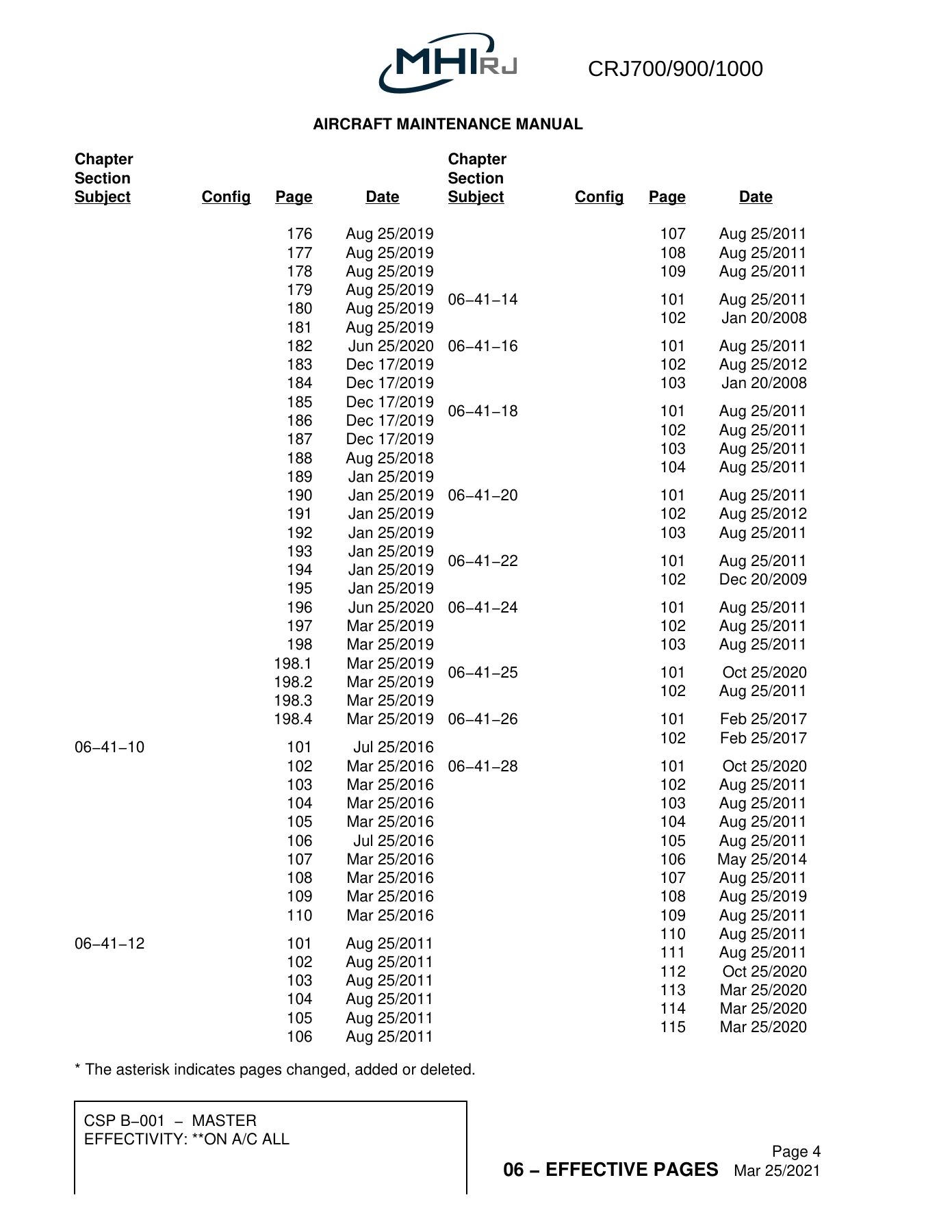
- Latest Effective Page Date: Mar 25/2021
Chapters Covered
- 06-10-00 Dimensions and Areas — General
- 06-20-00 Zones — Component Location
- 06-30-00 Stations — Component Location
- 06-31-00 Fuselage Stations
- 06-32-00 Vertical Stabilizer and Rudder Stations
- 06-33-00 Horizontal Stabilizer and Elevator Stations
- 06-34-00 Wing Stations
- 06-35-00 Nacelle and Pylon Stations
- 06-36-00 Stringers
- 06-40-00 Access — Component Location
- 06-41-02 External Fuselage Access Doors and Panels
- 06-41-04 External Fuselage Fairings
- 06-41-06 Flight Compartment Floor Panels
- 06-41-08 Passenger Compartment Floor Panels
- 06-41-10 Aft Baggage Compartment Floor Panels
- 06-41-12 Forward Baggage Compartment Floor Panels
- 06-41-14 Crawlway Floor Panels
- 06-41-16 Underfloor Structures Access Components
- 06-41-18 Flight Compartment Consoles and Flight Controls Access Panels
- 06-41-20 Flight Compartment Overhead Area Access Components
- 06-41-22 Flight Compartment Glareshield Access Panels
- 06-41-24 Flight Compartment FS280.00 Access Components
- 06-41-25 Entrance Storage Compartment Access Panels
- 06-41-26 Service Door Access Components
- 06-41-28 Galley Access Panels
- 06-41-29 Wardrobe Access Panels
- 06-41-30 Passenger Compartment Wall Access Components
- 06-41-32 Passenger Compartment Ceiling Access Components
- 06-41-34 Lavatory Access Components
- 06-41-36 Forward Baggage Bay Access Components
- 06-41-38 Aft Baggage Bay Access Components
- 06-41-40 Nose Landing Gear (NLG) Wheel Well Access Panels
- 06-41-42 Aft Equipment Compartment and Tailcone Access Panels
- 06-42-00 Empennage Access
- 06-43-00 Nacelle and Pylon Access
- 06-44-00 Wing Access
- 06-46-00 Doors Access
Taken as a whole, this chapter answers the two questions every CRJ technician asks first: where is it, and how do I get to it. The dimensions and areas material establishes the aircraft’s overall geometry and control-surface movement limits. The zones and stations material provides the three-digit zone system, the primary and unit zone breakdown, and the fuselage, wing, vertical stabilizer, horizontal stabilizer, rudder, elevator, aileron, flap, slat, nacelle, and pylon station reference planes. The access material then maps every openable or removable component to its five- or six-digit alphanumeric code, with the corresponding AMM task reference for removal.
Dimensions, Areas, and Control Movements
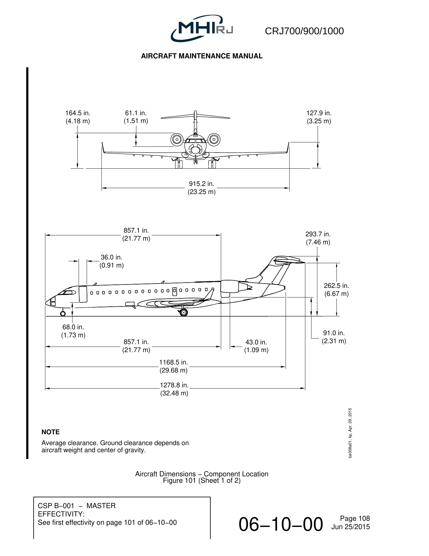
The chapter opens with the full aircraft dimension set for each model. General areas include the wing, aileron, horizontal stabilizer, elevator, vertical stabilizer, and rudder net and gross areas, plus baggage compartment volumes. The three-view dimension drawings cover the CRJ700, CRJ900, and CRJ1000 separately, with wingspan, fuselage length, tail height, wheelbase, and track measurements called out in both inches and metres.
Control-surface and control-movement data is tabulated for rudder, rudder pedals, control column, horizontal stabilizer, ailerons, aileron control wheel, elevators, multi-function spoilers, ground spoilers, and wing flaps. Door and overwing emergency exit dimensions are given for the passenger door, service door, overwing emergency exits, aft baggage compartment door, and forward baggage compartment doors. Landing gear data covers wheel size, tire size, unloaded tire pressure, track, wheelbase, and turning circle for each model.
Zones and Stations
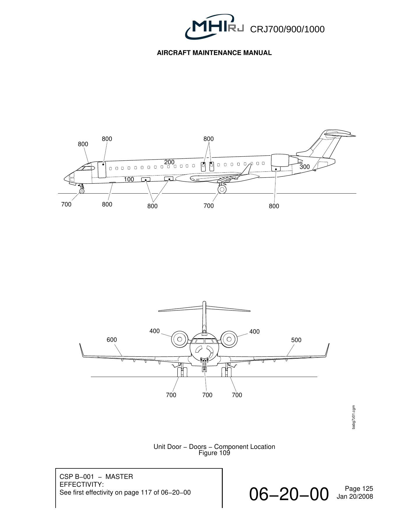
The zone system is presented in full: eight primary zones (100 through 800), the primary subzones for fuselage, empennage, landing gear, doors, wing, and power plant, and the unit zones that subdivide each primary subzone. The chapter explains the odd/even convention for left and right unit zones and lists every unit zone with its description and station boundaries.
Station coverage includes Fuselage Stations (FS), Wing Stations (WS), Aileron Stations (AS), Flap Stations (FLS), Slat Stations (SS), Nacelle Stations (XN), Vertical Stabilizer Stations (VSS), Horizontal Stabilizer Stations (HSS), Waterlines (WL), Buttock Lines (BL), and Maximum Half Breadth (MHB). The primary FS datum, primary WS datum, and the reference planes for each surface are defined, and station diagrams show the measured locations across the airframe.
Access Panel Identification
The access half of the chapter is the working heart of the document. It explains the two-group identification code — a three-digit zone number followed by a two- or three-letter location code — and the letter conventions for top, bottom, left, right, internal, floor, wall, and ceiling positions. It then lists, section by section, every access component on the aircraft with its panel code, type of access, what it gives access to, and the AMM removal task.
Sections cover external fuselage access doors and panels, external fuselage fairings, all interior floor panel groups (flight compartment, passenger compartment, aft baggage, forward baggage, crawlway), underfloor structures access, flight compartment consoles and flight controls, overhead area, glareshield, FS280.00 bulkhead components, entrance storage, service door, galley (multiple configurations), wardrobe, passenger compartment wall, passenger compartment ceiling, lavatory, forward and aft baggage bay, nose landing gear wheel well, aft equipment compartment and tailcone, empennage, nacelle and pylon, wing, and primary doors.
Each listing is tied to specific aircraft effectivity ranges — 10001–10999, 15001–15990, and 19001–19250 — and to specific service bulletins and pre/post SB configurations where the access arrangement differs, so the correct panel set can be identified for the exact aircraft being worked on.
Why This Chapter Matters
On a CRJ, you cannot remove the correct panel or interpret a station callout without this chapter. The station definitions tell you exactly where a measurement is taken from, the zone definitions tell you which structural bay you are looking at, and the access codes tell you which door or panel to open. Getting any one of those wrong means wasted labour, disturbed structure, or a component replaced on the wrong side.
This MHIRJ CRJ700/900/1000 Aircraft Maintenance Manual Chapter 06 Dimensions and Areas is written for the people who actually turn the wrenches, plan the inspections, and document the work — line maintenance, heavy maintenance, structures, avionics, interiors, and technical records.
Get Instant Access
Everything a technician needs to orient themselves on the CRJ700, CRJ900, or CRJ1000 is in this single chapter: the dimensions, the areas, the zone system, every station reference plane, and the complete access-panel index. Whether you are preparing a structural repair, tracing a system run, planning an interior removal, or simply confirming which panel covers a given component, this chapter gives you the correct answer without guesswork.
IMAGES PREVIEW
Delivered as an instant PDF download after purchase — no shipping, no waiting. Read it on a laptop, tablet, or phone in the hangar, print the station diagrams for the job pack, or keep it in your technical library for reference. This is the digital reference copy of MHIRJ Aircraft Maintenance Manual Chapter 06 for the CRJ700/900/1000.
Reviews
There are no reviews yet.