
Mindray BC-5390 CRP BC-5180 CRP Auto Hematology Analyzer Service Manual
Original price was: $49.95.$29.95Current price is: $29.95.
Comprehensive service manual for Mindray BC-5390 CRP and BC-5180 CRP Auto Hematology Analyzers, covering specifications, software, measurement principles, troubleshooting, fluidics, optics, electronics, mechanical assemblies, adjustments, maintenance and component replacement.
Description
The Mindray BC-5390 CRP BC-5180 CRP Auto Hematology Analyzer Service Manual is a detailed technical service reference for the BC-5390 CRP and BC-5180 CRP analyzers. It combines analyzer specifications and measurement principles with software configuration, diagnostic error information, fluidic and optical system documentation, electronic board coverage, mechanical assembly details, adjustment procedures and replacement instructions. The manual is intended for personnel working with analyzer servicing and assumes knowledge of circuits, fluidics, reagents, controls, troubleshooting, basic mechanical tools, digital voltmeters, oscilloscopes and pneumatic or hydraulic schematics.
File Details
- Manual type: Service Manual
- Brand: Mindray
- Models: BC-5390 CRP, BC-5180 CRP
- Equipment: Auto Hematology Analyzer
- Language: English
- Pages: 380
- File format: PDF
- Issued date: 2020-07
- Version: 11.0
Analyzer Coverage and Service Scope
This Mindray BC-5390 CRP BC-5180 CRP Auto Hematology Analyzer Service Manual begins with product configuration and operating requirements before moving into the analyzer’s software, measurement systems and service architecture. Product specifications include physical properties, environmental and power requirements, measurement and sample modes, sample requirements, report and research parameters, performance requirements, compatible tubes, reagents, controls and calibrators.
The analyzer supports CBC, CBC+DIFF, CRP and CBC+DIFF+CRP measurement modes. Sample handling coverage includes whole blood, predilute and capillary whole blood modes, with distinctions between autoloading and closed-tube operation. The manual also documents the major hematology and CRP parameters generated by the system, along with background limits, carryover requirements, repeatability, linearity and display ranges.
Measurement Principles and Analyzer Functions
A substantial portion of the manual explains how the analyzer produces its results. WBC differentiation is described using laser flow cytometry and scatter-light detection, while WBC and basophil counting also uses the impedance method. HGB measurement is documented through the colorimetric method, and RBC and PLT counting are explained using electrical impedance. CRP analysis is described through an intensified latex immunoturbidimetric method, including the CRP reaction and measurement flow.
The manual also explains parameter warning messages and the analyzer’s flagging logic. It identifies suspicious and confirmed conditions associated with WBC, RBC, PLT and CRP results and describes the related hiding and sensitivity-adjustment mechanisms used by the software.
Software, DMU and LIS Communication
The software chapter covers the analyzer software and PC-based DMU environment, including password levels, installation preparation, DMU installation and updating, PC-end analyzer software updates, connection setup between the DMU and analyzer, and LIS communication. The documented LIS functions include network communication, unidirectional and bidirectional operation, sample and QC transmission, worklist interaction, communication errors and troubleshooting information.
This makes the BC-5390 CRP and BC-5180 CRP service manual useful not only for mechanical or fluidic repair but also for service work involving analyzer software, external PC configuration, network communication and LIS/HIS integration.
Troubleshooting and Error Diagnosis
The instrument warning section provides extensive error-code based troubleshooting. Service information addresses pressure detection, temperature modules, syringe modules, sampling assemblies, board and voltage problems, autoloading mechanisms, reagent detection, flow cell clogging, abnormal background results, HGB abnormalities, aperture clogging, CRP errors and additional instrument faults. Entries identify the error mechanism and provide checks or corrective actions for the affected circuits, sensors, pumps, valves, motors, photocouplers, cables, boards and fluidic components.
Examples of documented service checks include pressure and vacuum behavior, reaction and optical temperatures, syringe home-position detection, sampling motor movement, board supply voltages, reagent availability, flow cell blockage, HGB blank voltage and CRP bath conditions. The manual therefore provides a structured path from an instrument warning to the assemblies and components that should be inspected.
Fluidics and CRP System Documentation
The fluidics chapter is one of the most detailed sections in the manual. It documents the DIFF and optical channel, WBC and HGB channel, RBC and PLT channel, and CRP channel. It includes analysis flow, sample volumes, temperature control, reagent consumption, valves, filters, syringes, pumps, sample probes, probe wipes, pressure relief devices, bubble removal, cistern and reaction baths.
Fluidic structure diagrams show how the channels, valves, pumps, syringes and baths are connected. Separate diagrams and sequences cover sample aspiration and dispensing, WBC/HGB operation, DIFF and optical flow, RBC/PLT processing and the CRP analysis path. Sequence descriptions explain the coordinated actions performed during sample aspiration, probe cleaning, reagent delivery and analysis. The manual also includes detailed information on the function of fluidic valves and associated service components.
Optical System Service
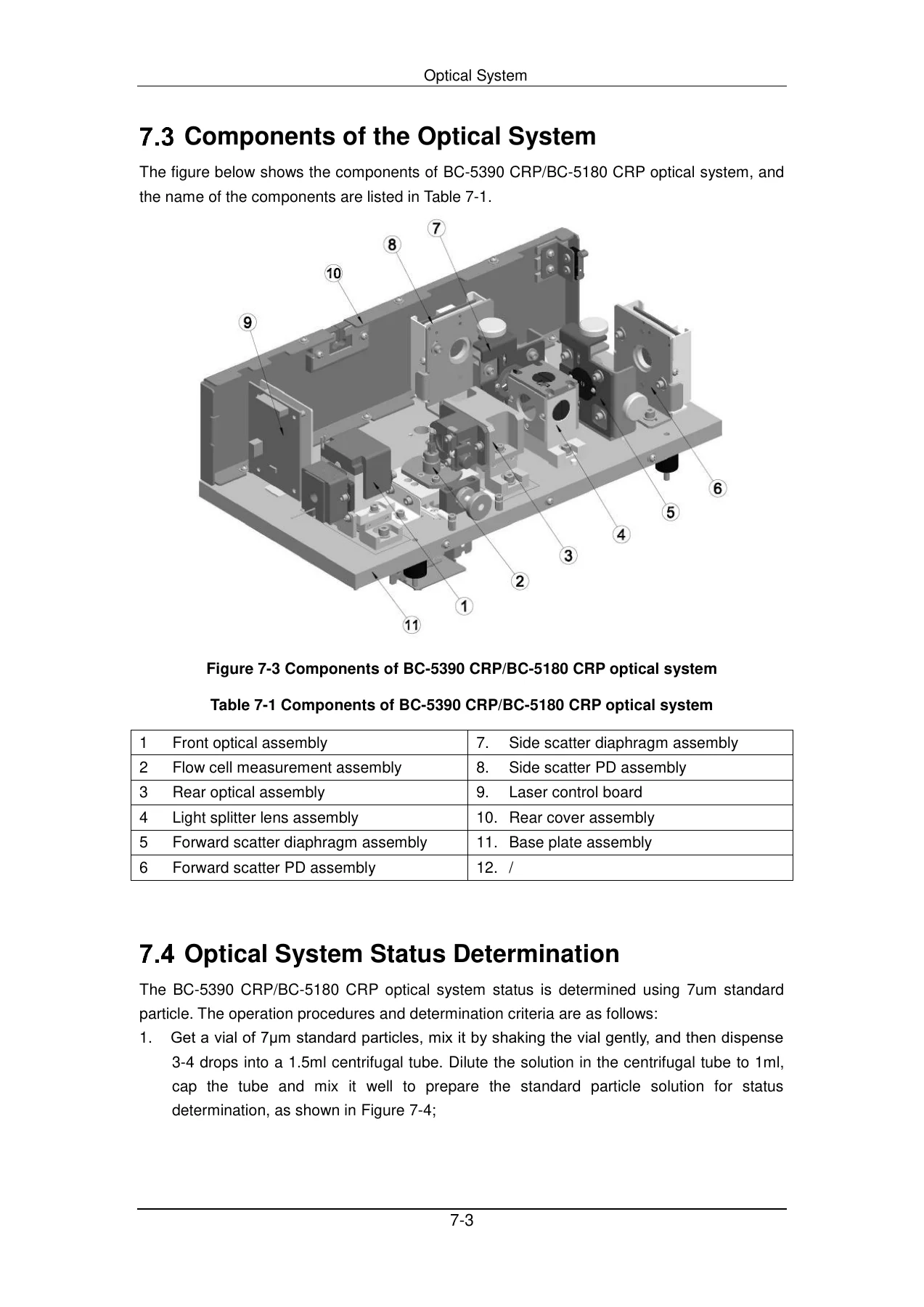
The optical system section explains the laser-based system used for WBC differentiation. It documents the optical path from the 670 nm semiconductor laser through the collimating and cylindrical lenses, flow cell, light splitter, forward-scatter optics and side-scatter optics. Component identification includes the front and rear optical assemblies, flow cell measurement assembly, scatter diaphragms, photodiode assemblies, laser control board and supporting structures.
Service procedures include optical system status determination using 7 μm standard particles, evaluation of FS and SS positions, gain checks, cleaning of the flow cell exterior and interior, handling of abnormal scattergrams, flow-cell clog service and complete optical-system replacement. Optical system gain calibration is also part of the chapter.
Hardware and Electronic Boards
The hardware chapter describes the electrical architecture of the analyzer and the individual electronic assemblies used for control, sensing, signal processing and power distribution. Coverage includes the analog board, digital control board and CPU module, drive board, autoloading board, laser control board, preamplification board, power board, fluid detection board, indicator board, key board, mini network board, CRP data board and 3112 power board.
Board sections identify functional modules, interfaces and signal connections. The manual also covers board socket prefixes, wiring and board connections, motors, photocouplers, micro-switches and analyzer status indicators. These sections support diagnosis of electrical faults and provide references for checking connections and replacing electronic assemblies.
Mechanical Assemblies, Adjustments and Replacement
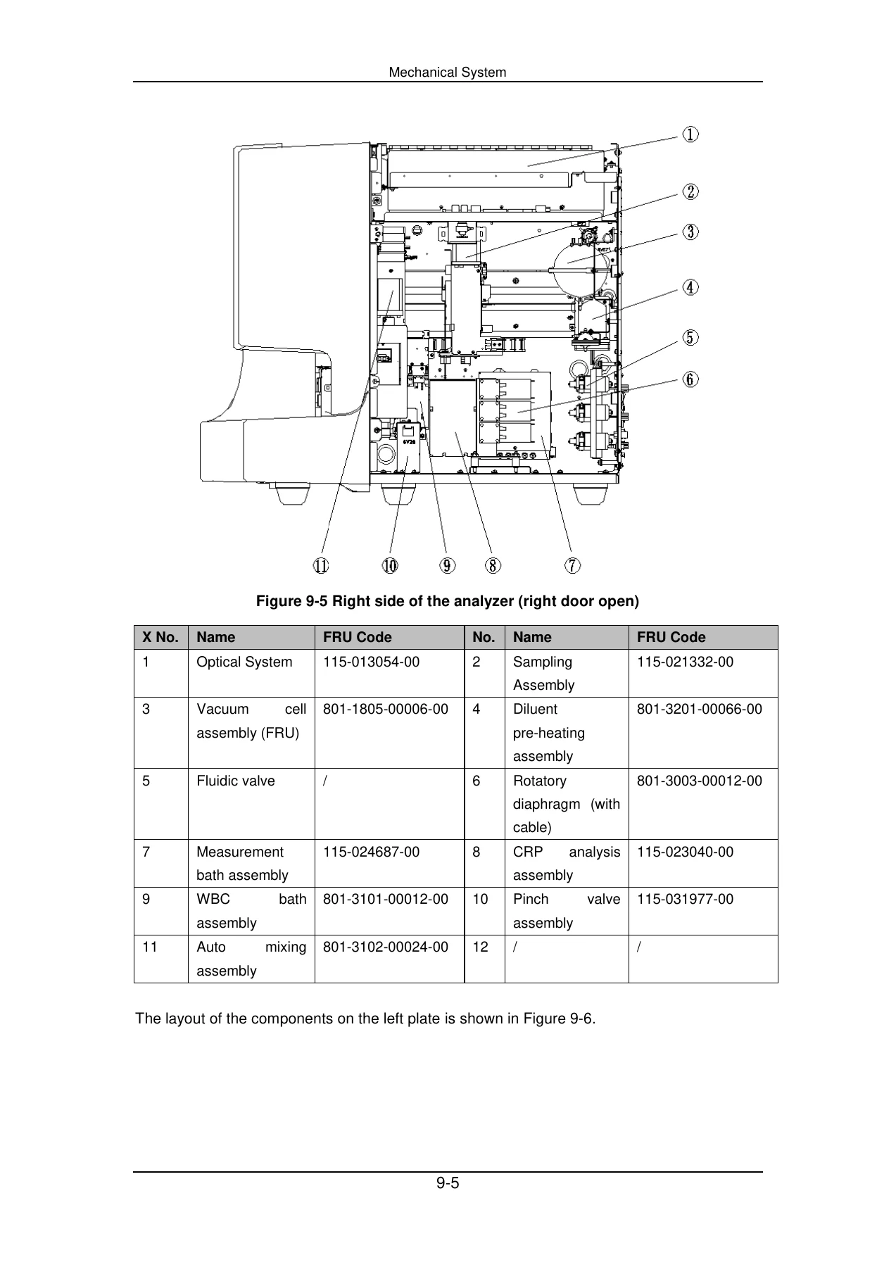
Mechanical coverage identifies the analyzer structure and internal component layout, including the optical system, sampling assembly, vacuum cell assembly, diluent pre-heating assembly, measurement baths, WBC bath, CRP analysis assembly, valves and auto-mixing components. The reagent thermostat and autoloading assembly is broken down into its loading, feeding, unloading, tube-detection, refrigeration and reagent-replacement components.
The service procedures extend to the mixing assembly, sampling assembly and syringe assemblies. Adjustment sections cover the sample probe position, clamp position, built-in barcode scanner and floating blood catch unit. The CRP analysis assembly is also documented as part of the mechanical system.
Chapters Covered
- 1 Using This Manual
- Scope
- Introduction
- General Operations
- Symbol
- 2 Product Specifications
- Name and Configurations
- Physical Properties
- Environment Requirements
- Power Requirements
- Measurement Modes and Sample Modes
- Sample Requirements
- Parameter
- Performance Requirements
- Applicable Tubes
- Reagents, Controls and Calibrators
- 3 Software System
- Overview and Password Function
- DMU Installation Instruction
- Frequently asked questions and the answers
- PC End Update
- Connection Setup of the DMU and Analyzer
- LIS Setup and Connection
- 4 Introduction of Major Parameters
- Parameter Sources
- WBC Measurement
- HGB Measurement
- RBC/PLT Measurement
- CRP Analysis
- Time Count Method
- Parameter Warning Messages
- 5 Instrument Warning Messages
- Error code
- 6 Fluidics
- Analysis Flow
- Sample Volume
- Temperature Control of the Fluidic System
- Reagent Consumption Volume
- Introduction of Fluidic Components
- Fluidic structure diagram
- Introduction of Sequences
- Function of Fluidic Valves
- 7 Optical System
- Overview of Optical System Principle
- Optical Path and Workflow of the Optical System
- Components of the Optical System
- Optical System Status Determination
- Maintenance and Replacement of the Optical System
- Optical System Gain Calibration
- 8 Hardware System
- Analog Board
- Digital Control Board including CPU module
- Drive Board and Autoloading Board
- Laser Control Board and Preamplification Board
- Power Board and Fluid Detection Board
- Indicator Board, Key Board and Mini Network Board
- CRP Data Board and 3112 Power Board
- Connections of Lines and Board
- Motors, Photocouplers and Micro-switches
- Analyzer Status Indicated by the Indicators
- 9 Mechanical System
- Analyzer Structure and Appearance
- Layout Introduction
- Reagent Thermostat and Autoloading Assembly
- Mixing Assembly
- Sampling Assembly
- Replace the Syringe Assembly
- Debug Screen Introduction
- Adjusting the Position of the Sample Probe
- Adjusting the Clamp Position
- Adjusting Built-in Barcode Scanner
- Floating Blood Catch Unit Adjustment
- CRP Analysis Assembly
- 10 Description and Replacement Instruction for Wearing Items
- When to Replace and the Tools Needed
- Replacing the reagent container
- Replacing Sample Probe
- Replacing Fuse
- Examining the Probe Wipe Filter and Air Filter
- Replacing the Rubber Pinch Valve
- Clean Closed Tube Probe Wipe and Catch Ring
- Replacing the Filter
- 11 Replacement Instruction for FRUs
- Replacement, Installation and Adjustment of CRP Analysis Assembly
- Replacement and Installation of Pinch Valves
- Replacement and Installation of Reagent Thermostat and Autoloading Assembly
- HGB Assembly Replacement
- Appendix
- CRP WX-BOM and supporting reference information
Taken together, these chapters provide a service technician with an integrated view of how the BC-5390 CRP and BC-5180 CRP analyzers measure samples, move fluids and reagents, process optical and electrical signals, communicate with the DMU and LIS, detect faults, and organize their replaceable electronic and mechanical assemblies.
Service, Repair and Diagnostic Reference
The Mindray BC-5390 CRP BC-5180 CRP Auto Hematology Analyzer Service Manual supports systematic troubleshooting, maintenance, adjustment and component replacement using the procedures, diagrams, error information and technical values documented for these analyzers. It is particularly useful when work involves fluidic faults, abnormal backgrounds, optical or flow-cell problems, sampling and autoloading mechanisms, electronic boards, reagent handling, CRP assemblies, HGB circuitry, software updates or analyzer communication.
IMAGES PREVIEW
Using the correct BC-5390 CRP and BC-5180 CRP service information helps technicians follow the specified checks, adjustment criteria, wiring and fluidic layouts, replacement sequences and verification steps rather than relying on general repair assumptions. Your purchase is supplied as an instant PDF download after payment, with no physical shipping required. The file can be opened on compatible computers, tablets and phones and can be printed for workshop or laboratory reference.
Reviews
There are no reviews yet.