
Mitsubishi 6M70 Diesel Engine Workshop Manual PDF – 6M70T2 6M70T4 Common Rail Repair
Original price was: $60.95.$37.95Current price is: $37.95.
Complete 364-page Mitsubishi 6M70 diesel engine workshop manual covering engine mechanical, common rail fuel and engine control, lubrication, cooling, intake and exhaust, and emission control. Includes diagnosis codes, service standards, tightening torques, exploded views and step-by-step removal and installation procedures for the 6M70T2 and 6M70T4.
Description
Mitsubishi 6M70 Diesel Engine Workshop Manual
This Mitsubishi 6M70 diesel engine workshop manual is the full service reference for the 6M70 series power unit, covering the engine mechanical assembly, the common rail fuel and engine control system, lubrication, cooling, intake and exhaust hardware, and emission control. It is arranged in seven numbered groups, each one self-contained, so a technician working on a 6M70 can move from a compression test on the cylinder head straight into a rail pressure diagnosis without switching documents. Every procedure is written around the engine as installed, with the service standards, tightening torques, special tool numbers and inspection limits printed alongside the steps they belong to.
The engine itself is a 6-cylinder, in-line, water-cooled, 4-cycle diesel with direct injection and an overhead camshaft (OHC) valve mechanism. Bore and stroke are Φ135 × 150 mm, total displacement 12,882 cm³ (12.882 L), and the compression ratio is 17.5. Maximum output is 309 kW (420 PS) at 2000 rpm and maximum torque is 1810 N·m (185 kgf·m) at 1100 rpm. Both the 6M70T2 and 6M70T4 variants are covered by the same groups.
File Details
- Manual type: Workshop Manual — diesel engine
- Brand: Mitsubishi
- Engine model: 6M70 (6M70T2 / 6M70T4)
- Language: English
- Page count: 364 pages
- File format: PDF
- Group coverage: General 00, Engine 11, Lubrication 12, Fuel and Engine Control 13, Cooling 14, Intake and Exhaust 15, Emission Control 17
Chapters Covered
- General 00
- Engine 11
- Lubrication 12
- Fuel and Engine Control 13
- Cooling 14
- Intake and Exhaust 15
- Emission Control 17
General 00 — Diagnosis Codes, Reading, Erasing and Standard Torques
The opening group explains how the two diagnosis code output methods work — the Multi-Use Tester and the flashing warning lamp on the meter cluster — and which systems support each method. It walks through the Multi-Use Tester connection using the V.C.I. and the harness set, the drive recorder function, and harness extension, then covers reading present and past codes and clearing them with the memory clear switch or the tester. A comprehensive table of standard tightening torques follows, split into hexagon head bolts and stud bolts, hexagon head flange bolts, hexagon nuts, hexagon flange nuts, and general-purpose flare nut and air piping nylon tube torques, all in N·m with kgf·m equivalents and strength grades from 4T through 8T.
Engine 11 — Engine Proper, Valve Mechanism, Pistons and Crankshaft
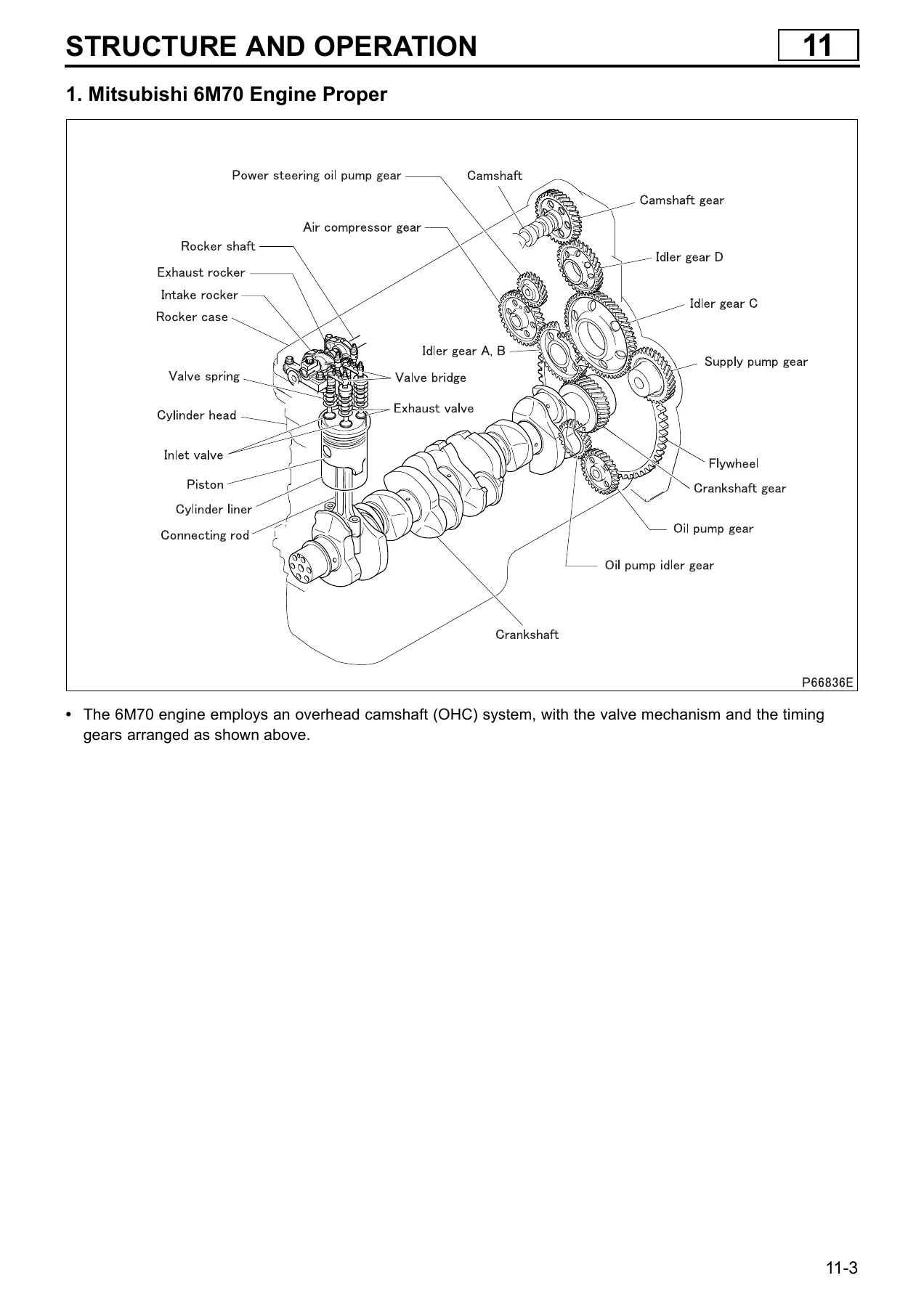
Group 11 is the largest section. It begins with structure and operation of the engine proper, the rocker and shaft, camshaft, rocker case and cylinder head gasket, the valve mechanism, connecting rod, piston, timing gears, flywheel, flywheel PTO, and the Powertard brake system. Troubleshooting tables map symptoms such as low power output and abnormal engine noise against cylinder head and valve mechanism faults, timing gear backlash, piston ring and liner wear, crankshaft bearing condition, and fuel or air supply problems. On-vehicle adjustment covers measuring compression pressure with the special gauge adapter, inspection and adjustment of valve clearances (intake 0.4 mm, exhaust 0.6 mm cold), and Powertard clearance adjustment (1.0 ± 0.05 mm cold).
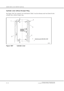
The group then takes the engine out of the frame and back in, with the front and rear hanger positions and mounting inspection and installation. Rocker cover, rocker and shaft, camshaft and rocker case, cylinder head and valve mechanism, piston, connecting rod and cylinder liner, flywheel PTO, flywheel, timing gears and crankshaft and crankcase each get their own disassembly sequence, service standards, tightening torques, lubricant and sealant points, special tools and inspection procedures. Notable details include the machined-together rocker case and camshaft caps, the plastic-region cylinder head bolts with punch-mark counting, the valve bridge and valve bridge guide clearance, valve stem seal replacement, valve seat refacing and lapping, cylinder liner flange protrusion and adjacent-liner step measurement, and the piston-to-liner size mark matching.
Lubrication 12 — Oil Pump, Cooler, Filters and Regulator Valve
Group 12 opens with a lubrication system flow diagram showing the full path from the oil strainer and gear-type oil pump through the relief valve, full-flow and bypass oil filters, the engine oil bypass alarm switch, the oil cooler and bypass valve, and on to the main oil gallery, before branching to the main bearings, connecting rod bearings and bushings, pistons via the check valves and oil jets, timing gears, camshaft journals, rocker shaft, turbocharger, supply pump and air compressor.
On-vehicle work includes oil filter replacement with the full-flow and bypass filter component breakdowns, engine oil replacement with the oil pan and filter drain plug torques and refill quantities, and oil pressure measurement using an adapter and gauge against the specified standard and limit values. The section also details removal and installation of the oil pan and oil jets, the oil pump, oil strainer and oil pipe assembly, the oil filter head and element, the oil cooler element with its air leakage test in a water tank, and the regulator valve with its opening pressure and spring installed load.
Fuel and Engine Control 13 — Common Rail, Supply Pump, Injector and Diagnosis
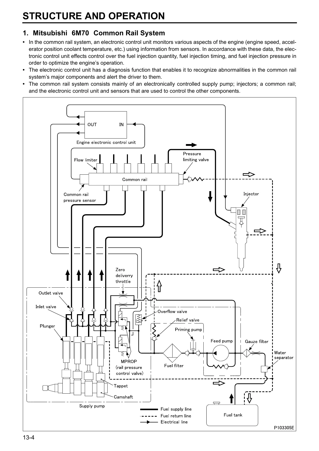
Group 13 explains the Mitsubishi 6M70 common rail system in full: the feed pump drawing fuel from the tank through the water separator, gauze filter and fuel filter to the MPROP (rail pressure control valve), the plungers and outlet valves pressurising fuel into the common rail, the flow limiters and pressure limiting valve, and the injector magnetic valves firing the injectors on commands from the engine electronic control unit. The supply pump is broken down around its camshaft, tappets, plungers, inlet and outlet valves and overflow valve, and the injector is shown in section with its control chamber, magnet, armature plate, valve ball, orifice A and orifice Z, valve piston, nozzle needle and nozzle spring.
Engine control functions covered include pilot injection, main injection and post injection, fuel injection quantity control during startup, basic and maximum injection quantity, the fuel injection rate adjustment resistor correction, main and pilot injection timing, fuel injection pressure control, the warm-up acceleration function, the auxiliary brake function, the idle-up function and the fault diagnosis function. The troubleshooting and Multi-Use Tester diagnosis section lists the full diagnosis code table with warning lamp flash counts and colours, then describes each code’s generation condition, recoverability, the control the electronic control unit applies in fault mode, and the inspection route. Service data lists, actuator tests, electronic control unit connector terminal layouts and terminal-level inspection values for every sensor and actuator follow, along with on-vehicle adjustment for no-load minimum and maximum speeds, fuel leakage inspection, injection pipe and fuel pipe clamp inspection, fuel tank deposit draining, air bleeding, fuel filter replacement, gauze filter cleaning and water separator element replacement.
Cooling 14 — Water Pump, Thermostat, Radiator and Belts
Group 14 describes the forced water circulation system, the wax pellet bottom bypass thermostat with jiggle valve, the belt-driven water pump with its drain hole protecting the unit bearing, and the automatic cooling fan coupling. Troubleshooting covers overheating, overcooling, abnormal noise and excessive coolant loss against belt condition, water pump mounting and unit seal, thermostat valve opening temperature, radiator core clogging and cracking, fan coupling bearing and bimetal condition, and oil cooler and cylinder head gasket faults. On-vehicle work includes belt tension inspection and adjustment with a belt tension gauge, belt condition assessment, coolant replacement and cooling system cleaning with FUSO RADIATOR CLEANER, air bleeding, gas leakage and coolant leakage tests, followed by removal and installation of the hoses and pipes, radiator and fan shroud, surge tank with pressure cap inspection, cooling fan and belt, water pump with flange and impeller interference checks, and thermostat with valve opening temperature and valve lift verification.
Intake and Exhaust 15 — Turbocharger, Intercooler, Manifolds and DPF
Group 15 covers the air cleaner with its unloader and vacuator valves, the TF08 variable geometry turbocharger with adjustable heat-resistant alloy turbine vanes, the turbocharger control system with its magnetic valves and air cylinder, and the continuously regenerating diesel particulate filter. Troubleshooting tables relate hard starting, black or white exhaust gas, poor power, excess oil consumption and abnormal intake or exhaust noise to air cleaner clogging, cartridge assembly bearing, shaft and turbine wheel damage, piston ring and insert wear, compressor and turbine housing fit, and intercooler or DPF restriction.
The turbocharger control system section provides its own diagnosis procedure, diagnosis code list and code generation conditions for over-boost, VGT magnetic valve 1, 2 and 3 circuits, turbine revolution sensor low and high signals, and turbine overrunning, together with Multi-Use Tester service data, actuator tests and electrical equipment inspection for the turbocharger magnetic valve and turbine speed sensor. On-vehicle work covers turbocharger boost pressure measurement and correction using the VGT test, air cleaner element cleaning and inspection, intake manifold bolt and nut looseness checks, exhaust manifold and turbocharger crack and gas leakage checks, then detailed removal and installation of the turbocharger and its attaching parts, the turbocharger itself down to cartridge assembly level, the intercooler with its air leakage test, the intake manifold, exhaust manifold with its seal rings and expansion rings, exhaust pipe, and diesel particulate filter.
Emission Control 17 — EGR System and Blowby Gas Return
Group 17 explains the exhaust gas recirculation system, in which engine speed, water temperature and accelerator position are collected and used by the engine electronic control unit and EGR EDU to drive the EGR magnetic valves, which in turn realise a seven-stage supply of air to the EGR valve and seven stages of valve lift. The EGR cooler reduces combustion temperature further by cooling the mixed exhaust gas. A full electronic control system block diagram, exhaust gas recirculation valve control function description and fault diagnosis function description are included, followed by the EGR diagnosis procedure, diagnosis code list and code generation conditions for the EGR 1, 2 and 3 circuits, the EDU relay and CAN communication with the EGR electronic drive unit, plus Multi-Use Tester service data, actuator tests and electrical equipment inspection.
The blowby gas return system section describes how blowby gases are introduced into the intake air duct for reburning, how the positive crankcase ventilation valve keeps crankcase pressure constant, and how oil in the blowby gas is separated by the wire mesh and element and returned to the oil pan, with the regulator valve bypassing a clogged element. On-vehicle work covers positive crankcase ventilation valve element replacement, crack and damage checks on the blowby gas return system piping, and crack, damage and looseness checks on the exhaust gas recirculation system piping, followed by removal and installation of the EGR valve, EGR magnetic valve, EGR pipe, EGR cooler with its exhaust gas and coolant passage air leakage tests, and the blowby gas return system with its PCV body, element, oil separator and hoses.
Why This 6M70 Workshop Manual Belongs in the Shop
Everything in this Mitsubishi 6M70 diesel engine workshop manual is written for the person doing the work, not for someone reading about it. The service standards are printed next to the procedure they apply to, so a valve clearance job, a Powertard clearance adjustment, a cylinder liner flange protrusion check or a main bearing oil clearance measurement can be carried out and signed off without hunting through a separate specification book. The tightening torque tables give both the N·m figure and the kgf·m equivalent, and the plastic-region bolts used on the cylinder head, connecting rod cap and main bearing cap are called out with their angle steps and their reusable punch-mark limits, so the fasteners are handled the way the engine expects.
The diagnostic content is just as practical. Because the 6M70 runs a common rail system with a supply pump, MPROP rail pressure control valve, flow limiters, a pressure limiting valve and electronically controlled injectors, the manual treats fault finding as part of the mechanical work rather than a separate electrical afterthought. Diagnosis code generation conditions, the control the electronic control unit applies while a fault is active, recoverability conditions, and the specific inspection route — service data item, actuator test, electronic control unit connector terminal, electrical equipment check — are listed for each code, so a rail pressure defect, an injector circuit fault, a VGT magnetic valve fault or an EGR circuit fault can be traced rather than guessed at. The connector terminal layouts and the resistance and voltage values measured at each terminal give a technician a concrete starting point before any component is removed.
The mechanical groups are equally complete. The Engine 11 section goes all the way down to the piston, connecting rod, cylinder liner, crankshaft and crankcase, with the size mark matching between piston, liner and crankcase, the crankshaft undersize dimensions for grinding, the crankshaft bend, roundness and cylindricity limits, and the crankcase top surface distortion check. The timing gear group lists the alignment marks for the camshaft gear, crankshaft gear, idler gears A and B, idler gear C and supply pump gear, along with the backlash values between each pair and the idler gear bushing clearance limits. The Powertard brake system is covered from its operating principle through the hydraulic pressure control circuit to the Powertard clearance adjustment, which matters on any 6M70 where the auxiliary brake is part of the working day.
On the intake and exhaust side, the TF08 variable geometry turbocharger is documented down to cartridge assembly level, with the compressor cover to compressor wheel clearance, the shaft and turbine wheel axial play, the turbine back plate clearance, the air cylinder stroke and airtightness values, and the nozzle lever plate play. The turbocharger boost pressure measurement procedure explains the correction calculations for intake air temperature, boost temperature and atmospheric pressure, and the adjustment guide tells you how much boost pressure changes per turn of the air cylinder joint. The diesel particulate filter section covers inspection for clogging and cleaning or replacement, and the EGR section provides the full EGR valve lift table across all eight operating steps and the air leakage tests for both the exhaust gas and coolant passages of the EGR cooler.
This is a 364-page PDF, delivered instantly after payment, with no shipping and no waiting for a disc. It opens on a laptop, tablet or phone, and any page can be printed for the workshop bench — the exploded views, the tightening torque tables, the diagnosis code lists and the wiring and circuit diagrams all print cleanly. Whether the job is a routine valve clearance and compression check, a full engine overhaul, a common rail injector or supply pump replacement, a turbocharger repair, or a diagnostic session on a stored fault code, this Mitsubishi 6M70 diesel engine workshop manual gives the procedure, the specification and the inspection limit in one place.
IMAGES PREVIEW
Reviews
There are no reviews yet.