

Nipro Diamax Single Patient Dialysis Machine Maintenance Manual MX2010-1704E6
Original price was: $44.95.$26.95Current price is: $26.95.
Factory maintenance manual for the Nipro Diamax Single Patient Dialysis Machine (Document No. MX2010-1704E6, software version 07.40 or later). Provides comprehensive servicing procedures, hydraulic flowcharts, printed circuit board schematics, balancing chamber overhauls, sensor calibrations, and maintenance inspection checklists across Machine Types 1 through 6.
Description
Overview of the Nipro Diamax Single Patient Dialysis Machine Maintenance Manual MX2010-1704E6
The Nipro Diamax Single Patient Dialysis Machine Maintenance Manual MX2010-1704E6 serves as the official, comprehensive technical guide for hospital biomedical engineers, service technicians, and qualified medical equipment specialists responsible for inspecting, maintaining, troubleshooting, and repairing the Nipro Diamax hemodialysis system. Designed specifically for single-patient acute and chronic renal failure treatments, the Diamax platform provides hemodialysis and sequential dialysis operating modes under strict clinical standards. This maintenance manual corresponds to Diamax units operating system software version Ver. 07.40 or later, detailing the complete functional and safety architecture for Class I, Type B electrical safety equipment with IPX1 fluid ingress protection.
Biomedical equipment technicians will find complete diagnostic workflows, alignment tolerances, and overhaul procedures covering every internal assembly. Whether you are executing routine six-month preventive maintenance, rebuilding Hicera ceramic metering pumps, resolving blood leak detector zerolize errors, or replacing surface-mounted card-cage printed circuit boards, the Nipro Diamax Single Patient Dialysis Machine Maintenance Manual MX2010-1704E6 delivers the manufacturer-specified technical parameters necessary to uphold clinical safety, dialysis fluid purity, and ultrafiltration accuracy.
File Details
- Manual Type: Maintenance Manual
- Brand: Nipro Corporation
- Model: Diamax (Single Patient Dialysis Machine)
- Document Number: MX2010-1704E6
- Software Compatibility: Version 07.40 or later
- Language: English
- File Format: PDF
Hardware Generations & Machine Type Distinctions
A central strength of the Nipro Diamax Single Patient Dialysis Machine Maintenance Manual MX2010-1704E6 is its exhaustive coverage of machine variations spanning multiple production generations. The manual details physical, hydraulic, and electrical distinctions across six distinct equipment classifications based on serial number coding:
- Machine Type 1 (Serial No. A0001* to A0207*): Configured with the large-size Techno Electric power supply unit, single 1500W cartridge heater, Pt100 temperature sensors (T1 to T4), independent pump mounting brackets, RV3 relief valve, and vertical dialyzer coupler holders.
- Machine Type 2 (Serial No. A0208* to A0609*): Features the compact Voltex power supply unit with integrated solid-state relay (SSR), transition to thermistor temperature probes (T1 to T4), unified Hicera pump brackets, elimination of RV3, and revised rear cover venting.
- Machine Type 3 (Serial No. C0001* to C8301*): Equipped with a Voltex power supply unit paired with an external SSR-Box and EMC shielding enclosure, dual-element heating system on 230V units (750W + 750W) or single 1500W element on 110V units, Type 2 UFP dual-direction rotary encoders, and horizontal dialyzer coupler assemblies.
- Machine Type 4 (Serial No. G8302* to G8701*): Integrates an internal SSR directly into the power unit with four heater connection terminals, incorporates Type 3 syringe pump drives, and migrates operational hour tracking into electronic maintenance data memory.
- Machine Type 5 (Serial No. J8702* to J10178*): Introduces support for Central Delivery System options, Type 3 Hicera piston pumps with 10-degree head angles (~0.35 mL stroke volume), advanced Type 3 optical blood leak detectors, and updated motherboard bus layouts.
- Machine Type 6 (Serial No. J10179* or later): Standardizes updated balancing chamber casing geometries with internal gap revisions, Type 3 operator touchscreen interfaces, and enhanced drip-proof sensor brackets.
Chapters Covered
- 1. Application: Clinical indications for acute and chronic renal replacement therapy, adult and pediatric hemodialysis, and sequential dialysis operational scope.
- 2. Contraindication: Restricted operating environments and clinical contraindications.
- 3. Precautions: Electrical safety classifications (Class I, Type B), electromagnetic compatibility, static electricity handling protocols, fluid penetration prevention, and software edition verification.
- 4. General Description: Complete technical specifications including equipment dimensions, dry weights (approx. 110 kg), acoustic sound pressure ratings, supply voltage tolerances, circuit breakers, fuses, water inlet requirements, drainage parameters, and hydraulic performance limits.
- 5. Regular Inspection: Technician qualifications, anti-static workwear guidelines, external cabinet disinfection cautions, and concentration connector sanitation procedures.
- 6. Maintenance Inspection: Periodic servicing schedules, interval tracking (3,500-hour pump overhauls, 5,000-hour or semi-annual comprehensive maintenance), and documentation standards.
- 7. Maintenance Manual: Detailed step-by-step physical and operational inspection protocols for water hoses, internal tubing, wiring harnesses, solenoid valves, pressure regulators, deaeration flow, gear pumps, blood pumps, syringe pumps, optical detectors, and safety alarms.
- 8. Maintenance Checklist: Field-ready preventative maintenance inspection checklists and service record tables arranged by subsystem.
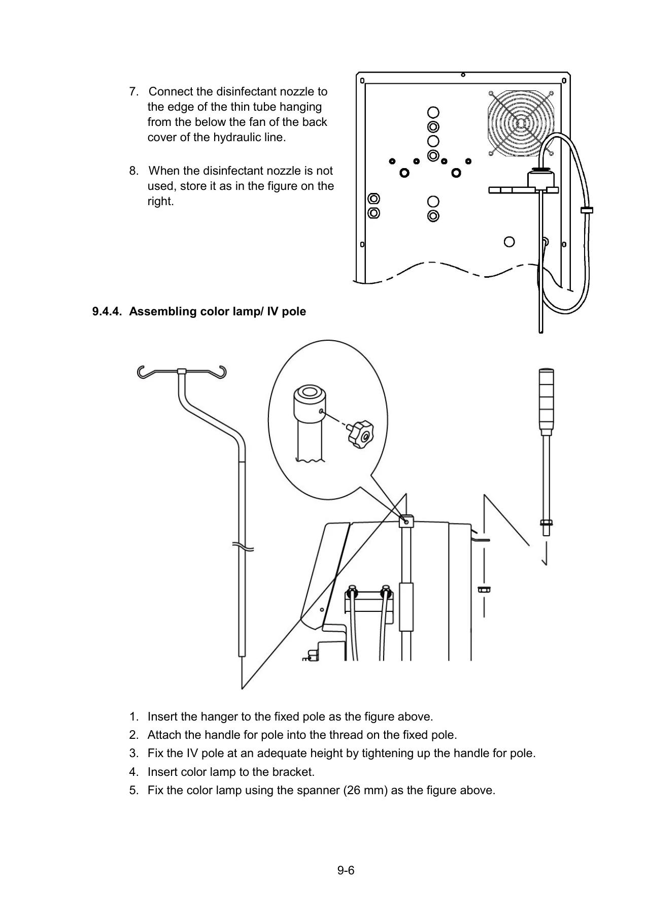
- 9. Installation: Environmental clearances, plumbing connections, drain hose head heights, IV pole and indicator lamp assembly, system water filling programs, date/clock setup, and technician PASS ID management.
- 10. Flowchart: Complete hydraulic piping schematics for Type 0 (Serial No. A0001* to A0207*) and Type 1 (Serial No. A0208* and later) fluid paths, detailing every valve, orifice, chamber, and sensor.
- 11. Replacement of Parts: Comprehensive periodic parts replacement matrices (Annual, 2-Year, 4-Year, At Failure intervals), exploded part diagrams, part code numbers, and component disassembly/reassembly procedures.
- 12. Composition of Electrical Equipment: Component layout diagrams for power supply bays, rear chassis, hydraulic cabinet electrical blocks, and operator panel revisions across Types 1 through 3.
- 13. Connection and Replacement of P.C. Board: Handling, connector pinouts, DIP switch configurations, test point voltages, and board-level replacement guides for Motherboards, CPU1 Control Boards, CPU2 Monitor Boards, Driver Boards, and LCD Interface Boards.
- 14. Technician Mode and Maker Mode: Password-protected menu hierarchies, software service modes, customized rinse program creation, disinfectant dwell configurations, and ultrafiltration/bicarbonate profile programming.
- 15. Adjustment: Mechanical and electronic calibration procedures for pressure regulator PR1, relief valves RV1/RV2, ultrafiltration volume coefficients, pressure transducers, temperature sensors, conductivity cells, blood sensors, and syringe drives.
- 16. Others: Flash memory software updates, touch panel screen coordinate calibration, 4-color status lamp diagnostic diagrams, battery backup operation, and pressure unit conversion charts.
- 17. Terminology: Technical acronyms, standard abbreviations, and medical dialysis equipment terminology.
Together, these seventeen chapters provide biomedical engineers with an end-to-end technical manual. From initial clinic unpacking and water quality validation to deep hydraulic rebuilding and circuit board level diagnostics, the manual ensures every servicing task conforms strictly to manufacturer engineering standards.
Hydraulic System Architecture, Degassing & Balancing Chambers
A critical focus of the Nipro Diamax Dialysis Machine Maintenance Manual is the operation and maintenance of the closed-loop hydraulic circuit. Proper dialysis fluid delivery relies on precise heating, negative-pressure deaeration, exact concentrate proportioning, and volumetric fluid balancing. The manual outlines the full fluid progression through every operational phase:
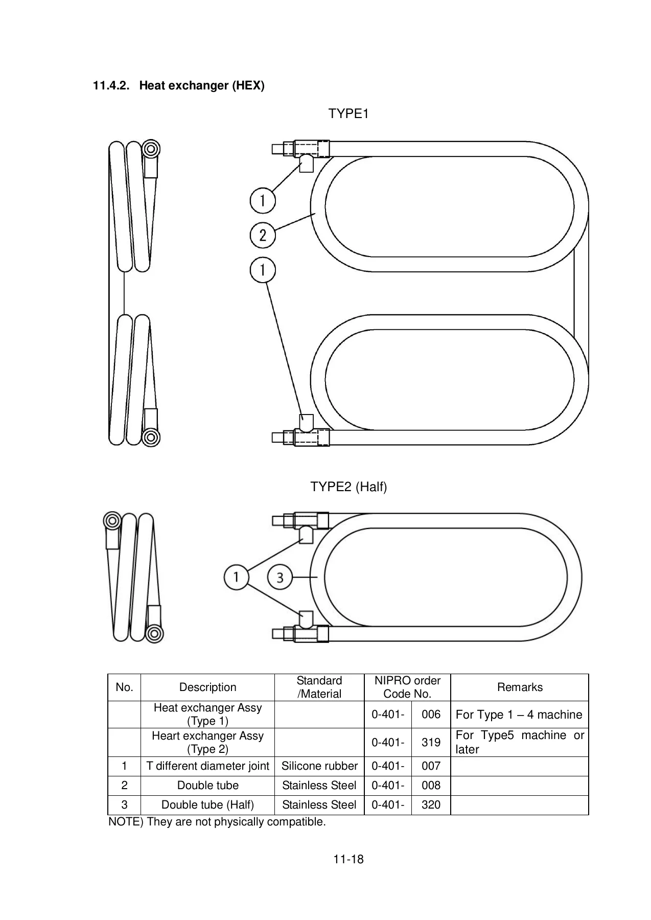
- Inlet & Degassing Circuit: Incoming treated dialysis water passes through pressure regulator PR1 (adjusted to 0.025 ± 0.01 MPa) and enters the stainless steel heat exchanger (HEX) and heater tank (BT). Heating is maintained between 30.0°C and 40.0°C with dual thermistor monitoring. The deaeration gear pump P1 draws negative pressure (-0.08 MPa or lower) across deaeration orifice OL3 to purge dissolved gases into the deaeration buffer tank (AS1) and air separator tank (AS2), where float switches evacuate trapped air.
- Proportioning & Mixing: Concentrates are metered via dedicated Hicera ceramic piston pumps—Pump P4 for B-liquid (bicarbonate) and Pump P5 for A-liquid (acid). Fluid conductivity is continuously validated by temperature-compensated conductivity sensor blocks (CD1 through CD4) spanning 10.0 to 17.0 mS/cm for total dialysate and 1.0 to 8.0 mS/cm for bicarbonate.
- Balancing Chambers (CHa & CHb): Fluid balancing is achieved through twin rigid volumetric chambers divided by flexible fluorocarbon rubber (FKM) diaphragms. Eight two-way solenoid valves (V21 through V28) cycle synchronously to deliver exact matched volumes of fresh dialysate to the dialyzer while extracting equivalent volumes of spent dialysate. The manual details chamber capacities (Type 1 casing: 223 mL; Type 2 casing: 248 mL), diaphragm replacement steps, and the critical requirement to match chamber shell types to prevent flow and conductivity alarms.
- Ultrafiltration (UF) System: Ultrafiltration removal is driven independently by piston pump P3, which extracts precise volumes directly from the balancing circuit. The manual provides detailed instructions for calibrating one-shot UF stroke volumes, setting correction coefficients (d and d′), and executing volumetric verification tests to guarantee fluid extraction accuracy within ±30 g/h at rates up to 3.00 L/h.
- Disinfection & Chemical Rinsing: Step-by-step fluid paths are provided for hot water disinfection (75°C to 85°C), citric acid decalcification, sodium hypochlorite disinfection, and peracetic acid sterilization, complete with automated dwell times and residual chemical test protocols.
Extracorporeal Circuit, Peristaltic Pumps & Safety Detectors
Patient safety during hemodialysis depends upon the flawless performance of the blood circuit modules. The Nipro Diamax Single Patient Dialysis Machine Maintenance Manual MX2010-1704E6 provides detailed diagnostic criteria, mechanical tolerances, and adjustment methods for every extracorporeal component:
- Peristaltic Blood Pump (BP1): Two-roller design with automatic tube gap adjustment springs supporting 8.0 mm large-bore tubing (25 to 600 mL/min) and 6.35 mm small-bore tubing (15 to 550 mL/min). Technicians are guided through occlusion gap verification, checking play and abnormal noise, blocking pressure tests holding 375 mmHg (±20 mmHg over 1 minute), and electronic flow rate calibration.
- Syringe Infusion Pump (HP): Microprocessor-controlled lead-screw drive supporting 10 mL, 20 mL, and 30 mL clinical syringes for heparin delivery. The manual details guide rod lubrication using Molykote G-n paste, half-nut engagement checks, overload switch activation thresholds (53.9 to 58.8 N load / 0.1 to 0.12 MPa pressure), bolus volume accuracy (±10%), and stroke ratio configuration in software.
- Air Bubble Detector (ABD): Ultrasonic transmission sensor capable of identifying single micro-bubbles from 0.3 μL to 10.0 μL and accumulated bubble volumes up to 1000 μL at blood flows of 200 mL/min, triggering immediate venous line clamp closure.
- Optical Blood Leak Detector (BLD): High-sensitivity optical sensor positioned on the dialysate effluent line detecting hemoglobin leakage from 0 to 370 ppm (alarm threshold 190 ppm at 32% hematocrit). Includes step-by-step procedures for glass flow-cell cleaning, avoiding optical scratching, clearing dirty sensor zerolize codes (errors 0113 and 1003), and installing the BLD Type 3 conversion unit on older chassis.
- Pressure Monitoring Transducers: Detailed servicing protocols for arterial pressure (PG4a), venous pressure (PG5), dialyzer inlet pressure (PG4b), and dialysate pressure (PG3), complete with zero-offset adjustments and span calibrations using external precision manometers.
IMAGES PREVIEW
Electronic Architecture, Board Diagnostics & Technician Service Modes
The electronic infrastructure of the Nipro Diamax centers on a modular card-cage rack linked via a heavy-duty motherboard. The manual outlines full electrical schematics, PCB jumper functions, diagnostic test points, and safety interlocks:
- Mother P.C. Board (BP02-14A / BP05-11 Series): Serves as the central communication backplane routing DC bus power (+24V, +12V, +5V, ±15V analog lines), valve solenoid drive signals, sensor inputs, and external communication links.
- Control P.C. Board (CPU1 – BP02-16B / BP05-12 Series): Governs pump speed control, proportional mixing algorithms, valve timing sequences, and user interface commands. The manual documents onboard DIP switches (SW2, SW3, SW4), analog reference test points (+2.500V, +3.333V, +5.120V), NVRAM chips (U18 and U30) for holding calibration data during board replacement, and lithium button cell replacement (CR2450) for system clock preservation.
- Monitor P.C. Board (CPU2 – BP02-17 / BP05-13 Series): Operates as an independent hardware safety watchdog, continuously auditing pump rotation speeds, temperature safety limits, conductivity windows, and venous clamp actuation. If discrepancies occur between CPU1 and CPU2, the system forces bypass mode and halts the blood pump.
- Driver P.C. Board (BP02-18B / BP05-14 Series): Interfaces logic signals with high-current actuators, driving the deaeration and dialysate gear pumps, UF stepping motors, and concentrate proportioning pumps.
- Technician & Maker Service Modes: Instructions for logging into protected machine software levels using authorized PASS IDs. Service screens allow real-time manual valve overriding (forced output), direct flow monitoring, digital sensor calibration without trimpot adjustment, custom weekly rinse program scheduling, and ultrafiltration profiling.
Professional Servicing Capability & Digital Delivery
Maintaining hemodialysis equipment demands total technical precision. Operating a dialysis system with drifted conductivity calibrations, worn piston pump lip seals, or misaligned venous clamps risks patient wellbeing and regulatory non-compliance. The Nipro Diamax Single Patient Dialysis Machine Maintenance Manual MX2010-1704E6 equips your technical department with the exact manufacturer engineering data, torque specifications, electrical pinouts, and calibration routines required to restore every machine to original factory specifications.
This manual is delivered as an instant, high-resolution digital PDF download immediately upon checkout. With no physical shipping wait, clinical engineering teams can resolve machine error codes, complete scheduled preventive maintenance overhauls, or source correct replacement part numbers without hospital downtime. Fully searchable and optimized for viewing on workshop computers, diagnostic laptops, tablets, or printed as a clean benchtop reference, this maintenance manual is the essential technical resource for maintaining the Nipro Diamax single patient dialysis platform.

Reviews
There are no reviews yet.