Description
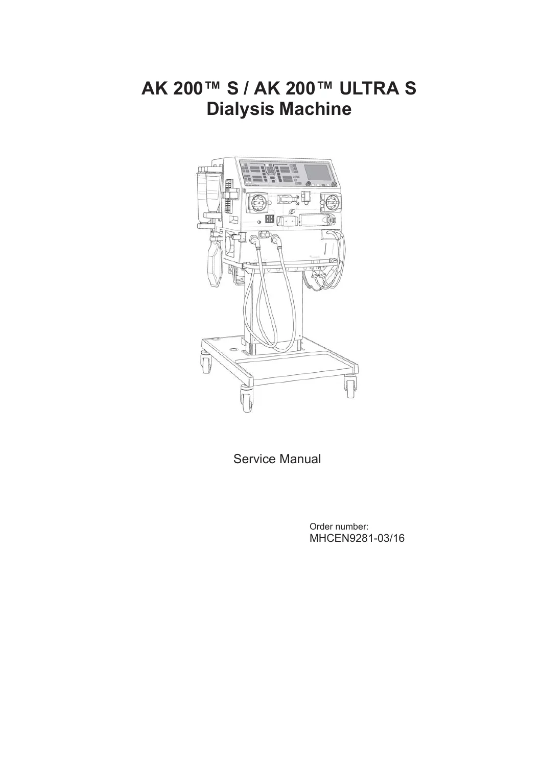
Complete Service & Repair Documentation for Gambro AK 200 S and AK 200 ULTRA S Dialysis Systems
This is the genuine, full-service manual for the Gambro AK 200 S and AK 200 ULTRA S dialysis machines. It is the essential technical resource for biomedical engineers, hospital technicians, and qualified service personnel responsible for the maintenance, calibration, and repair of these critical medical devices.
File Details
- Manual Type: Official Service Manual
- Brand / Manufacturer: Gambro Lundia AB
- Language: English
- Page Count: 270 Pages
- File Format: PDF (Digital Download)
- Document Number: MHCEN9281
- Revision: 03.2016
- Applicable Models: Gambro AK 200 S and Gambro AK 200 ULTRA S
Chapters Covered
This manual is structured to guide a service engineer through every aspect of the machine’s lifecycle, from initial installation to component-level repair. The key sections include:
- General Information: Manual purpose, disclaimer, maintenance schedules, required competence of service engineers, and safety symbols.
- Installation Guide: Detailed instructions for unpacking, mains voltage/power, water supply, drain connections, battery setup, and assembling the MS 200 and MS 202 monitor stands. Includes specific installation steps for the AK 200 S and AK 200 ULTRA S models.
- Maintenance Manual: Comprehensive preventive maintenance schedules, test equipment requirements, and step-by-step procedures for the Base-Kit, Supplementary A-Kit, and Supplementary B-Kit. Covers component exchange for the Fluid Monitor (FM) and Blood Monitor (BM).
- Replacements: Guidelines for component replacement, a replacement matrix, and specific instructions for changing batteries and the power supply cord.
- Maintenance Support Description: Detailed overview of the operator’s panel, treatment modes, display groups, and how to access and use the service/preset modes for logging, diagnostics, and configuration.
- Technical Description: In-depth technical breakdown of the Fluid Monitor (FM) and Blood Monitor (BM). Covers flow diagrams, valve functions, electrical circuit boards (CPU, Analog Distribution, Power Distribution), and component design.
- Technical Data and Specifications: Separate, detailed chapters for the AK 200 S and AK 200 ULTRA S, listing performance specs for the control system, supervisory system, physical data, materials in contact with fluids, and environmental data.
- Electrical Safety Inspection: Step-by-step procedures for performing Visual Inspections, Protective Earth Tests (PET), Earth Leakage Current Tests (ELT), and Patient Leakage Current Tests (PLT) with record sheets.
- Wiring Diagram: Electrical schematics for the BM and FM systems.
- Calibration Manual: Full calibration procedures for all major sensors and components in both the Fluid Monitor and Blood Monitor, including conductivity, pH, pressure transducers, and the blood leak detector.
- FM Flow Diagrams: Detailed fluid path schematics for the AK 200 S and AK 200 ULTRA S configurations.
The Gambro AK 200 S / AK 200 ULTRA S Service Manual is a critical diagnostic and repair resource. It provides certified technicians with the original factory procedures, component testing protocols, calibration values, and fault-finding flowcharts needed to ensure these machines operate safely and within their stringent performance specifications. Without access to this level of technical detail, performing accurate repairs and mandatory preventative maintenance is effectively impossible.
Complete PDF Bookmark Tree
Complete Bookmarks
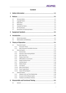
The complete bookmarks in the “Gambro AK 200 S & AK 200 ULTRA S Dialysis Machines Service Manual PDF (March 2016)” are as follows:
Table of contentsp. 3
+1 General informationp. 13
1.1 About this manualp. 14
1.2 Installationp. 14
1.3 Complaintp. 15
1.4 Disclaimerp. 15
1.5 Maintenancep. 15
1.6 Competence of Service Engineersp. 15
1.7 Repairp. 16
1.8 Technical supportp. 16
1.9 Waste disposalp. 16
1.10 List of symbolsp. 16
+2 Installation Guidep. 18
+2.1 Before installationp. 19
2.1.1 Qualification requirementsp. 19
2.1.2 Toolsp. 19
2.1.3 Manufacturerp. 19
2.2 Unpacking and inspectionp. 19
+2.3 Mains Voltage and Power Consumptionp. 20
2.3.1 Plugging in the machinep. 20
2.3.2 Power supplyp. 20
2.3.3 Service Outletsp. 21
2.3.4 Line Fusesp. 21
2.4 Mains Water Supplyp. 21
2.5 Drainp. 22
+2.6 Batteriesp. 22
2.6.1 9 V Batteryp. 22
2.6.2 Back-up Batteryp. 22
+2.7 Assembling the Monitor Standp. 23
2.7.1 Generalp. 23
2.7.2 MS 200 – Adjustable height: five fixed positionsp. 24
2.7.3 MS 200 – Adjusted for installation of WRO 300 / WRO 300 Hp. 27
2.7.4 MS 202 – Adjustable height: continuous variablep. 32
2.8 Positioning the dialysis machine on the standp. 37
2.9 Installation instructions for AK 200™ S dialysis machinep. 39
2.10 Installation instructions for AK 200™ ULTRA S dialysis machinep. 43
+2.11 Initial start-up procedurep. 47
2.11.1 First checkp. 47
2.11.2 Start-up procedurep. 48
2.12 Service reporting – installationp. 49
2.13 Checklist – installationp. 50
+3 Maintenance manualp. 52
3.1 Generalp. 53
3.2 Test equipmentp. 53
+3.3 Preventive maintenancep. 54
+3.3.1 Base-kitp. 54
3.3.1.1 Parts in the Base-kitp. 54
3.3.1.2 How to exchange the parts included in the Base-kitp. 55
3.3.1.3 Actions to carry out after the parts have been exchangedp. 60
+3.3.2 Supplementary A-kitp. 78
3.3.2.1 Parts in the Supplementary A-kitp. 78
3.3.2.2 How to exchange the exterior parts included in the A-kitp. 79
3.3.2.3 Actions to carry out after the parts have been exchangedp. 80
+3.3.3 Supplementary B-kitp. 82
3.3.3.1 Parts in the Supplementary B-kitp. 82
3.3.3.2 How to exchange the overhaul parts included in the B-kitp. 82
3.3.3.3 Actions to carry out after the parts have been exchangedp. 84
+3.4 Defibrillator usep. 84
3.4.1 Test after defibrillator usep. 84
3.4.2 Actions, test after defibrillator usep. 85
+4 Replacementsp. 86
4.1 Generalp. 87
+4.2 Replacement of componentsp. 87
4.2.1 Change actionsp. 87
+4.3 Replacement of Batteriesp. 89
4.3.1 List of batteries in AK 200™ S and AK 200™ ULTRA S dialysis machinesp. 89
4.3.2 Battery and electronic waste handlingp. 89
4.4 Replacement of power supply cordp. 89
+5 Maintenance support descriptionp. 90
+5.1 Operator's panelp. 92
5.1.1 Buttons and displaysp. 92
+5.1.2 Treatment overviewp. 93
5.1.2.1 Blood and fluid pathsp. 93
5.1.2.2 Parameter buttonsp. 94
5.1.2.3 Bargraph displaysp. 94
+5.1.3 Stand-by groupp. 94
5.1.3.1 Stand-by group buttonsp. 94
5.1.3.2 Alarm buttonsp. 95
+5.1.4 Display and setting groupp. 95
5.1.4.1 Overviewp. 95
5.1.4.2 Viewing trends on the screenp. 95
5.1.4.3 Colours in parameter displaysp. 96
5.1.5 Light intensity adjustmentp. 97
+5.1.6 Light intensity on old panelsp. 97
5.1.6.1 Bargraph contrastp. 97
5.1.6.2 Backlightp. 98
5.1.7 Treatment overview screenp. 98
5.1.8 Functional check overview screenp. 100
+5.2 Maintenance support overviewp. 101
5.2.1 Available test proceduresp. 101
5.2.2 Access the Maintenance Support Selectionp. 101
5.2.3 To Exitp. 101
+5.2.4 Logging modep. 101
5.2.4.1 Logging mode overviewp. 101
5.2.4.2 Logging mode flow diagramp. 102
5.2.5 Arraysp. 103
5.2.6 AK 200™ S dialysis machine Flow path with S-variablesp. 104
5.2.7 AK 200™ S UFD dialysis machine Flow path with S-variablesp. 105
5.2.8 AK 200™ ULTRA S dialysis machine Flow path with S-variablesp. 106
5.2.9 Logging diagram, S-variables for BMp. 107
5.3 How to enter/exit Service/Preset modep. 108
+5.4 Preset modep. 108
5.4.1 Custom settingp. 108
5.4.2 Configurationp. 109
5.4.3 PC Presetp. 110
+5.4.4 Othersp. 110
5.4.4.1 Language versionp. 110
5.4.4.2 Time settingsp. 111
5.4.4.3 Total defaultp. 111
5.4.5 Start up modep. 112
5.4.6 Preset of concentratesp. 114
+5.5 Service modep. 117
5.5.1 How to enter service modep. 117
5.5.2 Service mode flow diagramp. 118
5.5.3 Blood monitor flow diagram, calibrationp. 119
5.5.4 Fluid monitor flow diagram, calibrationp. 120
5.5.5 Diagnostic flow diagramp. 121
5.5.6 Error Buffers flow diagramp. 122
5.5.7 Diagnostics BMp. 123
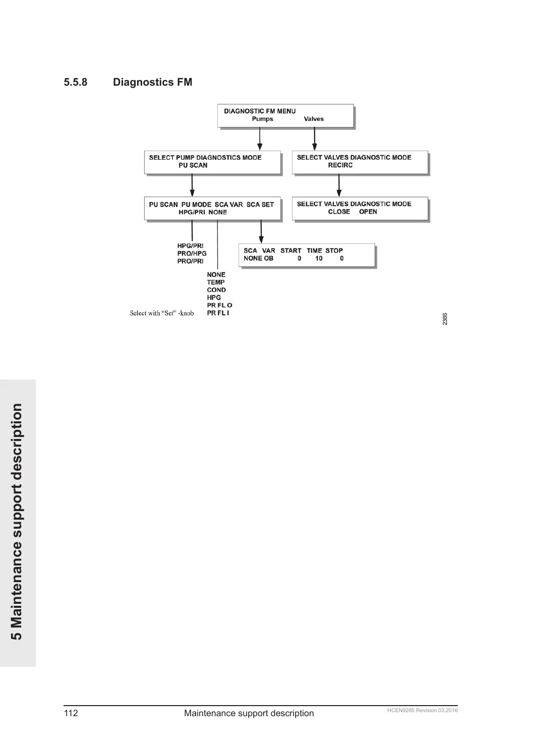
5.5.8 Diagnostics FMp. 124
5.5.9 Utility flow diagramp. 125
5.5.10 Exalis® flow diagramp. 126
+5.5.11 Download new program versionp. 127
5.5.11.1 Tools neededp. 127
5.5.11.2 Download softwarep. 127
+6 Technical descriptionp. 130
+6.1 Introductionp. 132
6.1.1 Generalp. 132
+6.1.2 Main functionsp. 133
6.1.2.1 Overviewp. 133
6.1.2.2 Quick preparation proceduresp. 133
6.1.2.3 Treatment flexibilityp. 133
6.1.2.4 Disinfectionp. 134
6.1.2.5 Optionsp. 134
6.1.2.6 Othersp. 134
6.1.3 Parametersp. 134
+6.2 Fluid Monitor, FMp. 135
6.2.1 Fluid Monitorp. 135
6.2.2 FM flow diagram AK 200™ ULTRA S dialysismachinep. 136
+6.2.3 Treatmentp. 137
6.2.3.1 Water intakep. 137
6.2.3.2 Concentratep. 137
6.2.3.3 Concentrate – FMp. 138
6.2.3.4 BiCart Select® Systemp. 138
6.2.3.5 Dialysis Fluidp. 138
6.2.4 Design and Constructionp. 141
6.2.5 FM valvesp. 146
+6.2.6 Electrical circuit boards used in the fluid monitorp. 148
6.2.6.1 Wiringp. 148
6.2.6.2 FM CPU boardp. 148
6.2.6.3 FM Analog Distribution boardp. 151
6.2.6.4 FM Power Distribution boardp. 151
6.2.6.5 Blood leak Detector boardp. 151
6.2.6.6 Conductivity cell boardp. 151
6.2.6.7 Blood pressure monitor boardp. 151
+6.3 Blood Monitor, BMp. 152
6.3.1 Blood Monitorp. 152
+6.3.2 Treatmentp. 153
6.3.2.1 Double Needle Treatment – HDp. 153
+6.3.2.2 Single Needle Treatmentp. 154
6.3.2.2.1 Single Pumpp. 154
6.3.2.2.2 Double pumpp. 155
+6.3.2.3 Double Needle Treatmentp. 156
6.3.2.3.1 Flow diagramsp. 156
6.3.2.3.2 HDF Low Volumep. 156
6.3.2.3.3 HDF on linep. 156
6.3.2.3.4 HF on linep. 157
+6.3.3 Design and Constructionp. 157
6.3.3.1 Level Detector (Air detector)p. 157
6.3.3.2 Batteriesp. 157
6.3.3.3 Blood Pump Unitp. 157
6.3.3.4 BVS – Blood Volume Sensorp. 157
6.3.3.5 Drip Chamber Level Adjustmentp. 158
6.3.3.6 Fanp. 158
6.3.3.7 Heparin Pump Unitp. 158
6.3.3.8 Line Clamp Unitp. 158
6.3.3.9 Operator's Panelp. 158
6.3.3.10 Pressure Transducersp. 158
6.3.3.11 Priming Detectorp. 159
6.3.3.12 BPM – Blood Pressure Monitorp. 159
+6.3.4 Electrical circuit boards used in the blood monitorp. 160
6.3.4.1 Wiringp. 160
6.3.4.2 BM Analog Distribution Boardp. 160
6.3.4.3 Jumpers on the BM Analog Distribution boardp. 160
6.3.4.4 Panel Control Boardp. 160
6.3.4.5 Jumpers on the Panel Control Boardp. 160
6.3.4.6 BM CPU Boardp. 161
6.3.4.7 Jumpers on the BM CPU boardp. 161
6.3.4.8 Connectors on the BM CPU Boardp. 162
6.4 Power Supplyp. 163
6.5 Monitor standp. 164
+7 Technical data and specifications – AK 200™ S dialysis machinep. 166
+7.1 Performance and specification – Control Systemp. 167
7.1.1 Notesp. 167
7.1.2 Blood Flow Controlp. 167
7.1.3 Air Detectionp. 167
7.1.4 Heparin Administrationp. 168
7.1.5 Blood Volume Sensor (BVS)p. 168
7.1.6 Blood Pressure Monitor (BPM)p. 168
7.1.7 Dialysis fluid preparationp. 168
7.1.8 Dialysis fluid preparation (BiCart Select® concentrate system mode only)p. 169
7.1.9 Ultrafiltration controlp. 169
7.1.10 Profilingp. 170
7.1.11 Diascan®p. 170
7.1.12 Disinfection and Cleaningp. 171
7.1.13 Water supplyp. 174
7.1.14 Drainp. 174
7.1.15 Power supplyp. 174
7.1.16 Connection of external equipmentp. 175
7.1.17 Battery Back-upp. 176
+7.2 Performance and specification – Supervisory systemp. 176
7.2.1 Valid accuracy rangep. 176
7.2.2 Blood Pressure Supervisionp. 176
7.2.3 Air Detectionp. 177
7.2.4 Heparin Administrationp. 177
7.2.5 Dialysis fluid preparationp. 177
7.2.6 Dialysis fluid preparation (BiCart Select® concentrate system mode only)p. 178
7.2.7 Ultrafiltrationp. 178
7.2.8 Blood leak detectionp. 178
7.2.9 Blood loss due to coagulationp. 178
7.3 Physical datap. 178
+7.4 Materials in contact with water, concentrates and dialysis fluidp. 179
7.4.1 Polymersp. 179
7.4.2 Metalsp. 179
7.4.3 Othersp. 179
+7.5 Environmental datap. 180
7.5.1 Operationp. 180
7.5.2 Transportation and storagep. 180
7.5.3 Energyp. 180
7.5.4 Electromagnetic environmentp. 180
7.6 Standardsp. 183
+8 Technical data and specifications – AK 200™ ULTRA S dialysis machinep. 184
+8.1 Performance and specification – Control Systemp. 185
8.1.1 Notesp. 185
8.1.2 Blood Flow Controlp. 185
8.1.3 Air Detectionp. 185
8.1.4 Heparin Administrationp. 186
8.1.5 Blood Volume Sensor (BVS)p. 186
8.1.6 Blood Pressure Monitor (BPM)p. 186
8.1.7 Dialysis fluid preparationp. 186
8.1.8 Dialysis fluid preparation (BiCart Select® concentrate system mode only)p. 187
8.1.9 Ultrafiltration controlp. 188
8.1.10 Substitution fluidp. 188
8.1.11 Profilingp. 188
8.1.12 Diascan®p. 188
8.1.13 Disinfection and Cleaningp. 189
8.1.14 Water supplyp. 191
8.1.15 Drainp. 191
8.1.16 Power supplyp. 191
8.1.17 Connection of external equipmentp. 192
8.1.18 Battery Back-upp. 193
+8.2 Performance and specification – Supervisory systemp. 193
8.2.1 Valid accuracy rangep. 193
8.2.2 Blood Pressure Supervisionp. 193
8.2.3 Air Detectionp. 194
8.2.4 Heparin Administrationp. 194
8.2.5 Dialysis fluid preparationp. 194
8.2.6 Dialysis fluid preparation (BiCart Select® concentrate system mode only)p. 195
8.2.7 Ultrafiltrationp. 195
8.2.8 Blood leak detectionp. 195
8.2.9 Blood loss due to coagulationp. 195
8.3 Physical datap. 195
+8.4 Materials in contact with water, concentrates and dialysis fluidp. 196
8.4.1 Polymersp. 196
8.4.2 Metalsp. 196
8.4.3 Othersp. 196
+8.5 Environmental datap. 197
8.5.1 Operationp. 197
8.5.2 Transportation and storagep. 197
8.5.3 Energyp. 197
8.5.4 Electromagnetic environmentp. 197
8.6 Standardsp. 200
+9 Electrical Safety Inspectionp. 201
9.1 Generalp. 202
9.2 Visual inspectionp. 202
+9.3 PET – Protective Earth Testp. 203
9.3.1 Test equipment for PET – Protective Earth Testp. 203
9.3.2 PET (Protective Earth Test) for AK 95™ S dialysis machinesp. 203
9.3.3 PET (Protective Earth Test) for AK 96® dialysis machinep. 203
9.3.4 PET (Protective Earth Test) for AK 200™ S / AK 200™ ULTRA S dialysis machinesp. 204
+9.4 ELT / PLTp. 204
9.4.1 Test equipment for ELT / PLTp. 204
9.4.2 General conditions for ELT / PLTp. 204
9.4.3 ELT – Earth Leakage Current Testp. 205
9.4.4 PLT – Patient Leakage Current Testp. 206
9.5 Record of Electrical Safety Inspectionp. 208
10 Wiring diagramp. 211
+11 Calibration manualp. 214
11.1 Generalp. 216
+11.2 Calibration, Fluid Monitorp. 216
11.2.1 Technical Facilitiesp. 216
11.2.2 A/D Converter FM (CPU Q), FM 21p. 217
11.2.3 A/D Converter FM (CPU F;1), FM 22p. 218
11.2.4 A/D Converter FM (CPU F;2), FM 23p. 219
11.2.5 Temperature FM CPU Board calibration, FM 0p. 220
11.2.6 Degassing Transducer calibration, FM 7p. 221
11.2.7 Flow Output Pressure Transducer calibration, FM 8p. 222
11.2.8 Flow Input Pressure Transducer calibration, FM 9p. 224
11.2.9 High Pressure Guard Transducer calibration, FM 10p. 225
11.2.10 Dialysis Fluid Pressure Transducer (PD) calibration, FM 11p. 227
11.2.11 Safety Guard Pressure Transducer calibration, FM 12p. 228
+11.2.12 pH-sensor calibration, FM 13p. 230
11.2.12.1 Equipment neededp. 230
11.2.12.2 Calibration stepsp. 230
11.2.12.3 Offset calibrationp. 230
11.2.12.4 Complete calibrationp. 231
11.2.13 Blood Leakage Detector calibration, FM 24p. 232
11.2.14 Internal pressure regulator calibration (AK 200™ ULTRA S dialysis machine only)p. 233
11.2.15 Inlet pressure regulator adjustmentp. 234
11.2.16 Conductivity Transducer calibration, FM 20 – with liquid concentratep. 235
11.2.17 Conductivity Transducer calibration, FM 20 – with SelectCart cartridgep. 236
+11.2.18 BiCart Select® – Level detector calibrationp. 238
11.2.18.1 Equipment neededp. 238
11.2.18.2 Generalp. 238
11.2.18.3 Calibration instructionp. 239
11.2.18.4 Trouble shootingp. 240
+11.2.19 BiCart Select® – control and protective pump calibrationp. 240
11.2.19.1 Equipment neededp. 240
11.2.19.2 Generalp. 240
11.2.19.3 Preparationsp. 241
11.2.19.4 Calibration instructionp. 242
11.2.19.5 Verificationp. 243
+11.2.20 Calibration of Flow Restrictor Node (FRN) main flow supervisionp. 243
11.2.20.1 Generalp. 243
11.2.20.2 Calibration instruction, with liquid concentratep. 244
11.2.20.3 Calibration instruction, with SelectCart cartridgep. 245
11.2.20.4 Trouble shootingp. 245
+11.2.21 Automatic UF calibration/Supervision flowmeter calibrationp. 246
11.2.21.1 Equipment neededp. 246
11.2.21.2 Generalp. 246
11.2.21.3 Running the UF calibration, with liquid concentratep. 247
11.2.21.4 Running the UF calibration, with SelectCart cartridgep. 247
11.2.21.5 Verification of the UF cell calibrationp. 248
+11.3 Calibration, Blood Monitorp. 249
11.3.1 A/D Converter BM(CPU P), BM 4p. 249
11.3.2 Venous Pressure Transducer calibration, BM 3p. 251
11.3.3 Arterial Pressure Transducer calibration, BM 2p. 253
11.3.4 System Pressure Transducer calibration, BM 1p. 255
11.3.5 Level Detector calibration (Air detector), BM 5p. 256
11.3.6 Trouble shootingp. 257
11.3.7 Priming Detector calibration, BM 6p. 258
11.3.8 Blood Volume Sensor – BVSp. 258
11.3.9 Temperature BM CPU Board calibration, BM 0p. 258
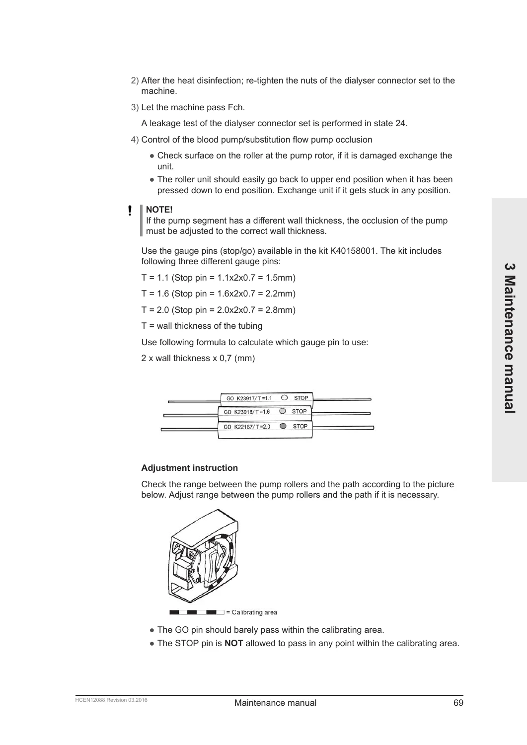
11.3.10 Occlusion adjustment, blood pump/substitution flow pumpp. 259
+11.3.11 BPM testp. 260
11.3.11.1 Equipment neededp. 260
11.3.11.2 Test methodp. 260
11.3.11.3 BPM sub-testp. 261
11.3.11.4 Check of air leakagep. 261
11.3.11.5 Check of inflation speedp. 262
11.3.11.6 Check of pressure transducer calibration and measured pressurep. 262
+11.4 Logging after calibrationp. 262
11.4.1 GXL-loggingp. 262
11.4.2 Procedurep. 263
11.4.3 Logging valuesp. 263
12 FM flow diagramsp. 265
Essential for Biomedical and Service Professionals
This manual enables a qualified service engineer to perform the full range of necessary tasks, including:
- Correctly installing the machine, stand, and all external connections.
- Carrying out mandatory preventive maintenance every two years to ensure reliability and safety.
- Accurately calibrating all critical sensors (conductivity, pH, pressure transducers, air detectors).
- Performing essential electrical safety tests to meet medical equipment standards (IEC 60601-1).
- Diagnosing and repairing errors using the detailed error code descriptions and component-level replacement procedures.
- Understanding the complex fluid and blood flow paths to troubleshoot performance issues.
Having the correct technical documentation is paramount in a medical setting. Using the Gambro AK 200 S & AK 200 ULTRA S Dialysis Machines Service Manual ensures that all repairs and calibrations are carried out to the manufacturer’s exacting standards, minimizing downtime and ensuring patient safety. This Gambro AK 200 ULTRA S service manual and Gambro AK 200 S repair manual are the authoritative source for all service procedures.
Upon your purchase, you will receive an instant download link to the PDF file. You can view it on your computer, tablet, or mobile device, and print specific pages as needed for use in the workshop or service area. No physical item will be shipped.

Reviews
There are no reviews yet.