
VG70 Ventilator Service Manual – Edition 01.04 (May 2018) PDF Download
Original price was: $39.95.$24.95Current price is: $24.95.
Official Aeonmed VG70 Critical Care Ventilator service manual. Covers pneumatic/electrical systems, disassembly, maintenance, calibration, and troubleshooting. Edition 01.04, May 2018.
Description
VG70 Ventilator Service Manual – Edition 01.04 (May 2018)
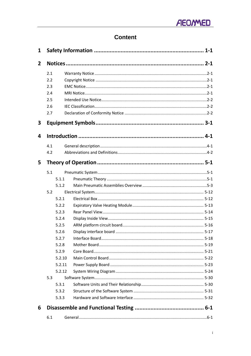
This is the complete VG70 Ventilator Service Manual, Edition 01.04, published in May 2018. Designed for authorized service engineers, this comprehensive manual provides all the technical information required for servicing and maintaining the Aeonmed VG70 Critical Care Ventilator. This PDF document is the official guide for understanding the ventilator’s complex pneumatic and electrical systems, performing disassembly and assembly, conducting functional tests, and using the service menu for calibration and diagnostics. It is an essential resource for biomedical engineers, hospital technicians, and service personnel working on this life-support equipment.
Document Details
- Manual Type: Service Manual
- Brand/Model: Aeonmed VG70 Critical Care Ventilator
- Edition: 01.04
- Date: May 2018
- Language: English
- Page Count: 133 Pages
- File Format: PDF
Chapters Covered
The manual is systematically organized into 15 chapters and several appendices, covering every aspect of the ventilator’s service and maintenance:
- 1. Safety Information: Warnings and cautions for operators and service personnel.
- 2. Notices: Warranty, copyright, EMC, MRI, intended use, and declaration of conformity.
- 3. Equipment Symbols: Explanation of symbols used on the equipment.
- 4. Introduction: General description of the system and abbreviations/definitions.
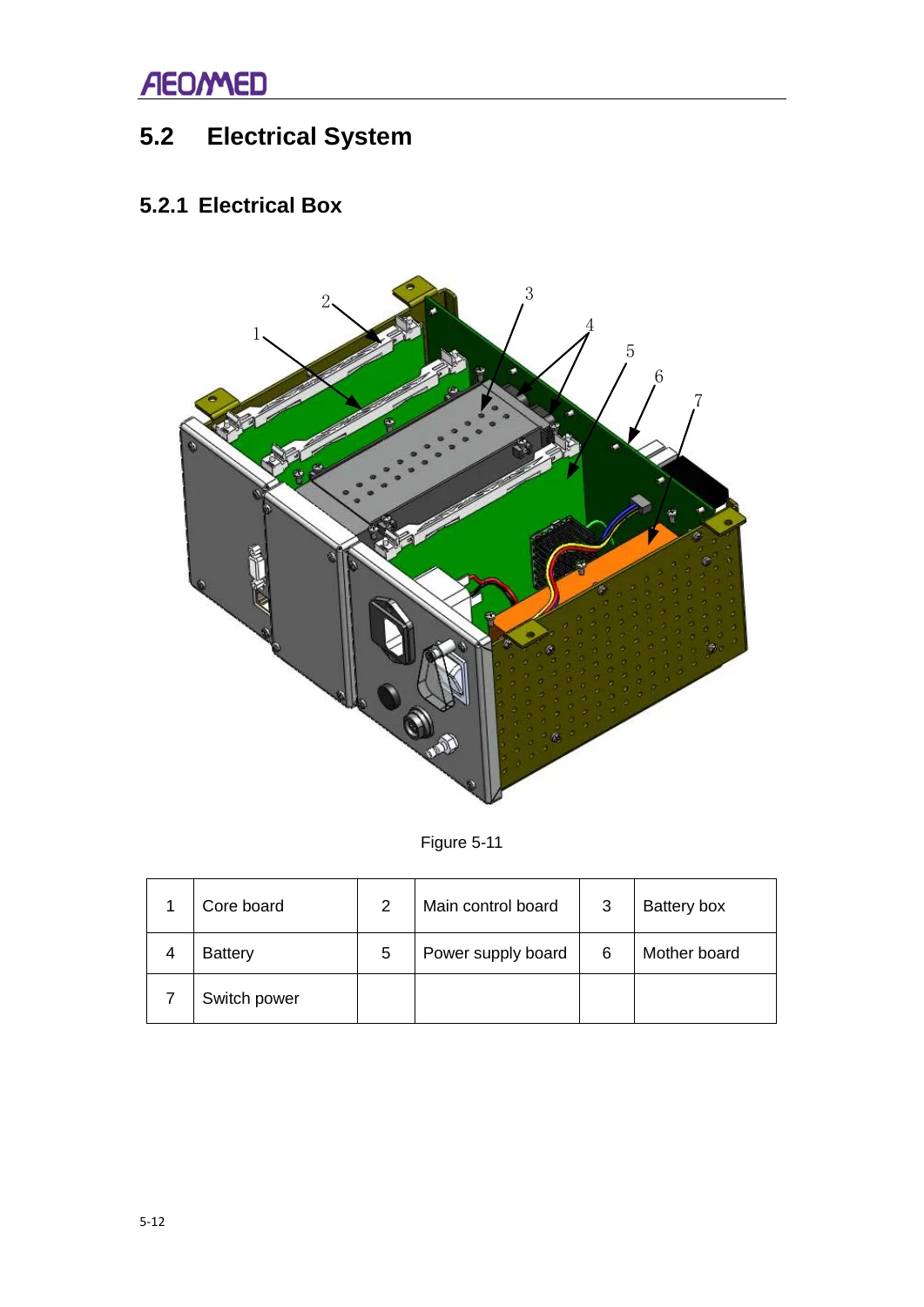
- 5. Theory of Operation: Detailed explanation of the pneumatic system (including the oxygen inlet and mixer modules, turbine, and safety inspiratory module), electrical system (with a breakdown of all circuit boards like the Core, Main Control, Power Supply, and Interface boards), and the software system architecture.
- 6. Disassemble and Functional Testing: Step-by-step instructions for disassembling main assemblies (display, host, arm, humidification) and maintenance spare parts (oxygen sensor, pressure sensor board, TSI mass flow sensor, differential pressure transmitter, diaphragm, etc.) along with comprehensive functional testing procedures.
- 7. User Maintenance: Cleaning and disinfection guides, regular maintenance schedules, service life of components, transportation/storage instructions, fuse replacement, battery maintenance, and oxygen sensor care.
- 8. Pre-Use Test (PUT): Procedures for the pre-use test, including technical, battery, gas supply, and sensor tests, plus failure analysis.
- 9. Network: Information on exporting patient monitoring data via HL7 over a LAN, including establishing connections and interface instructions.
- 10. Service Menu: Detailed walkthrough of the service menu, including calibration for pressure, flow, O2, CO2, inspiratory/expiratory valves, touch screen, leak, and circuit tests. Also covers event/alarm logs, machine information, update procedures, and more.
- 11. Troubleshooting: Comprehensive error code list (including technical test error codes) and troubleshooting steps for other errors.
- 12-15. Appendices: Contact/ordering information, diagrams and schematics (including a pneumatic diagram), product specifications, and spare parts/configurations list.
The VG70 Service Manual is the definitive guide for all service-related tasks. It allows a trained technician to safely disassemble the ventilator, replace critical components like the turbine, flow sensors, and circuit boards, and then use the built-in service menus to calibrate the new parts. The manual provides the correct procedures and specifications necessary to ensure the ventilator is functioning within its design parameters, which is critical for patient safety. It covers everything from basic daily maintenance and fuse replacement to advanced diagnostics using the error code system and schematic test page.
Key Systems and Components Covered
- Pneumatic System: Theory and operation of the gas circuit, including the oxygen inlet module, oxygen mixer module (with its bank of solenoid valves), turbine and inspiratory control module, and the safety inspiratory module.
- Electrical System: Detailed identification and description of all major circuit boards (Core Board, Main Control Board, Mother Board, Power Supply Board, Interface Board, etc.), system wiring diagrams, and the expiratory valve heating module.
- Software System: Explanation of the software units (User Interface, Breathing Delivery, Power Supply), their relationships, and the hardware-software interface.
- Maintenance & Calibration: Step-by-step instructions for user maintenance, cleaning/disinfection, and detailed calibration procedures for all major sensors and valves.
- Disassembly & Assembly: Procedures for disassembling the entire system, from the display to the internal pneumatic and electrical components.
This service manual is an indispensable tool for maintaining the VG70 Ventilator, helping to ensure its reliability, accuracy, and safety for patients. The information contained within is vital for proper servicing, avoiding physical injury, and preventing equipment damage.
Instant PDF Access
This is a complete, digitally scanned PDF of the original VG70 Ventilator Service Manual. Upon purchase, you will receive immediate access to download the file. It can be viewed on any computer, tablet, or smartphone, allowing you to have the information you need directly at your workstation without the need for a physical, easily damaged paper manual. The pages are clear and reflect the original publication, providing an exact reference for your service needs.
Why This Manual is Essential
Proper maintenance and service of a critical care ventilator like the VG70 is not just a matter of equipment longevity; it is a matter of patient safety. This manual provides the only authoritative source for the correct procedures, specifications, and part numbers. Using this guide, a qualified service engineer can confidently diagnose issues, perform repairs, and ensure the ventilator is calibrated to factory standards after any service. This directly contributes to the machine’s life-support functionality. It is an investment in the proper performance of the equipment and the safety of the patients who depend on it.

Reviews
There are no reviews yet.