★ TRUSTED BY 321,897+ PROFESSIONALS WORLDWIDE
🏢
Trusted Business
Verified & Licensed
🛡️
Virus Free Files
100% Safe Downloads
🔒
Secure Payment
SSL Protected
Instant Delivery
Available Immediately
Sale!

PHILIPS INTERA 1.0 / 1.5 T MRI System Operator and Service Manual – 12.5m Mobile Unit

Original price was: $39.95.Current price is: $24.95.

Complete operator and service manual for the PHILIPS INTERA 1.0 / 1.5 T MRI System mobile trailer. Covers setup, transport, safety systems, electrical, generator, HVAC, hydraulic lift, and maintenance. 126 pages.

Instant PDF Download
Available immediately
💾
Save to Your Device
Download & keep forever
🛡️
Antivirus Scanned
100% virus-free
🌍
Trusted Worldwide
175,000+ customers

Description

File Details

  • Manual Type: Operator and Service Manual
  • Document Number: 10295-D01-00
  • Release Date: February 2008
  • Brand / System: PHILIPS INTERA 1.0 / 1.5 T MRI System
  • Mobile Unit: 12.5m L x 2.5m W x 3.8m H Japan Unit
  • Manufacturer: Oshkosh Specialty Vehicles
  • Language: English
  • Total Pages: 126
  • File Format: PDF

Chapters Covered

  • Section 1: Introduction
  • Section 2: Safety Guidelines
    • General Safety Precautions
    • Magnet Safety
    • Chemical Safety
    • Electrical Safety
    • Transportation Safety
  • Section 3: Safety Systems
    • Door Interlock System
    • Emergency Lighting
    • Fire Suppression & Detection
    • Gauss Lines & Magnetic Field
    • Oxygen Monitor
    • Roll Door & System Shutdowns
    • Warning Lights (400V, Air Bag, Transport, Generator OFF)

    IMAGES PREVIEW

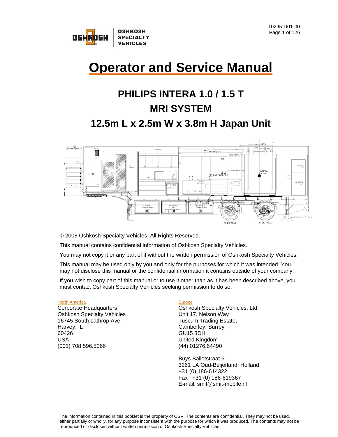
    PHILIPS INTERA 1.0 / 1.5 T MRI System Operator and Service Manual - 12.5m Mobile Unit — PDF page 1 preview
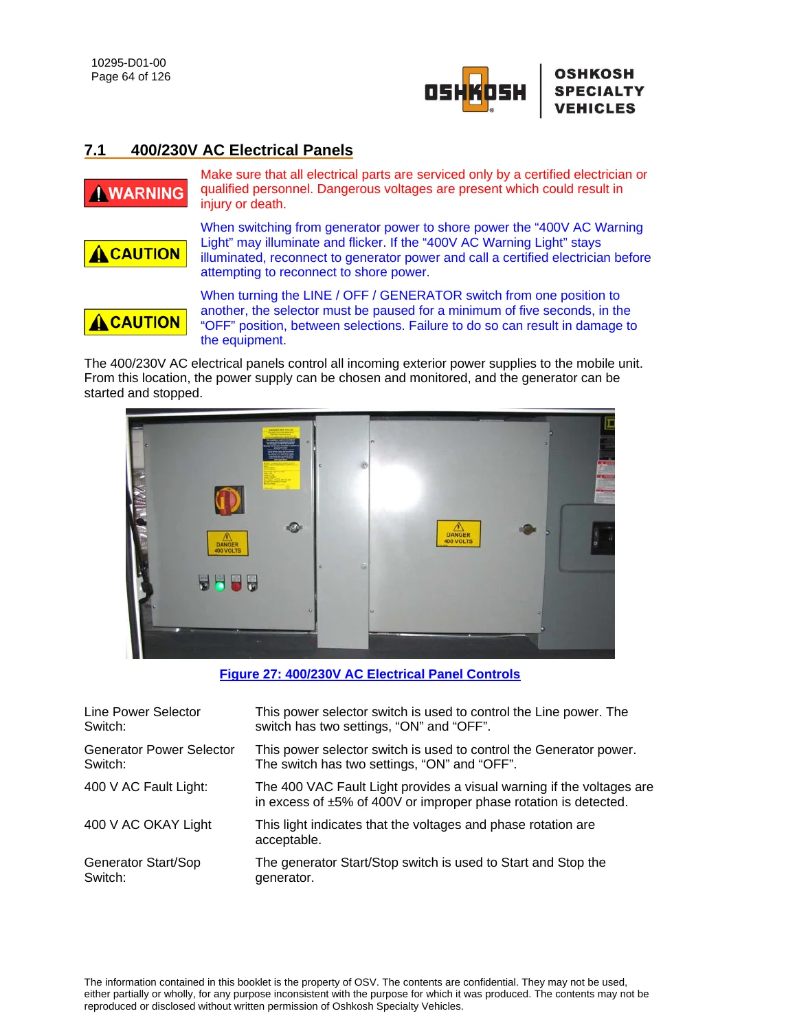
    PHILIPS INTERA 1.0 / 1.5 T MRI System Operator and Service Manual - 12.5m Mobile Unit — PDF page 64 preview
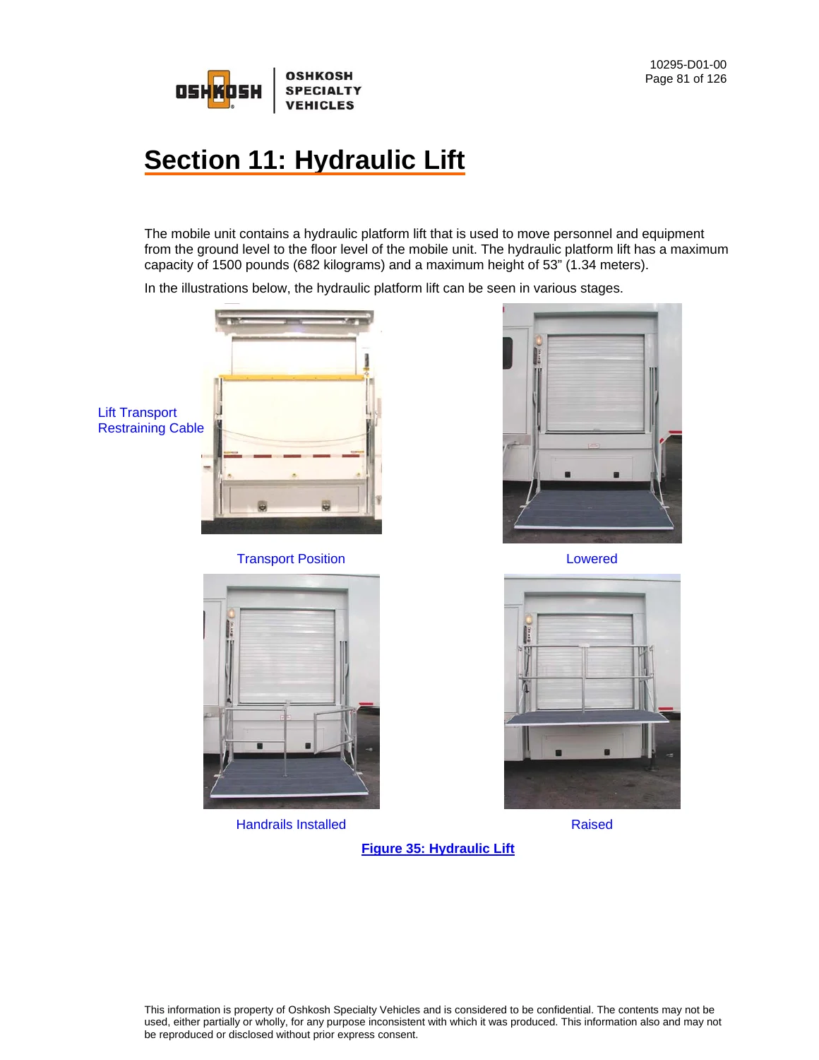
    PHILIPS INTERA 1.0 / 1.5 T MRI System Operator and Service Manual - 12.5m Mobile Unit — PDF page 81 preview

  • Section 4: Mobile Unit Overview
    • Air Ride Control Valves
    • Canopy (optional)
    • Control Room, Equipment Room, Scan Room
    • Cryogen Compressor
    • Fuel Compartment & Glad-hand Connections
    • Interior Door & I.V. Track Rail
    • Levels & Stabilizing Stands
    • Phone & Data Connections
  • Section 5: Mobile Unit Setup Procedure
  • Section 6: Mobile Unit Transport Procedure
  • Section 7: Electrical System (400/230V AC Panels, Facility Power)
  • Section 8: Generator System
  • Section 9: Humidity System
  • Section 10: HVAC System
    • Air Conditioning & Chiller
    • Exterior & Interior HVAC Specs
    • Underbody Compartment Heater
  • Section 11: Hydraulic Lift (Safety, Operation, Transport)
  • Section 12: Intrusion Alarm (optional)
  • Section 13: Landing / Stabilizing Legs
  • Section 14: Lighting System (Emergency, Exterior, Interior, Warning Lights)
  • Section 15: General Maintenance (Daily, Weekly, Monthly, Quarterly)
  • Section 16: Specific Maintenance (Door Closer, Electrical, Generator, Humidity, HVAC, Lift, RF Shielding)
  • Appendices: Checklists, Troubleshooting, HVAC Set Points, Lockout/Tagout, Quarterly Maintenance Checklist

Complete PDF Bookmark Tree

Complete Bookmarks

The complete bookmarks in the “PHILIPS INTERA 1.0 / 1.5 T MRI System Operator and Service Manual – 12.5m Mobile Unit” are as follows:

Operator and Service Manualp. 1
List of Revisions & Warningsp. 3
Revisionsp. 3
Noticep. 3
Warnings & Safety Alert Conventionsp. 4
Table of Contentsp. 5
List of Figuresp. 10
Section 1: Introductionp. 13
Section 2: Safety Guidelinesp. 15
2.1 General Safety Precautionsp. 15
2.2 Magnet Safetyp. 16
2.3 Chemical Safetyp. 16
2.4 Electrical Safetyp. 16
2.5 Transportation Safetyp. 17
Section 3: Safety Systemsp. 19
3.1 Door Interlock Systemp. 19
3.2 Service Door Equipment Roomp. 20
3.3 Emergency Lightingp. 20
3.4 Fire Suppression (manual)p. 21
3.5 Fire Detection Systemp. 21
System Operation – Firep. 23
System Operation – Faultp. 23
Test Smoke / Heat Alarmsp. 24
Test Call Pointsp. 24
3.6 Gauss Linesp. 25
3.7 Hydraulic Liftp. 25
3.8 Magnet Field Indicatorp. 26
3.9 Marker Lightsp. 26
3.10 Oxygen Monitor (Optional)p. 26
3.11 Roll Doorp. 27
3.12 System Shutdownsp. 27
Guarded Magnet Quench Button (Emergency Rundown Unit)p. 28
Manual Shutdown (Emergency Stop)p. 28
3.13 Warning Lightsp. 28
400 VAC Fault Lightp. 28
Air Bag Suspension Warning Lightp. 29
Transport Warning Lightp. 29
Generator OFF Warning Lightp. 29
Section 4: Mobile Unit Overviewp. 31
4.1 Air Ride Control Valvesp. 31
4.2 Canopy (optional)p. 32
4.3 Control Room Overallp. 33
4.4 Cryogen Compressorp. 34
4.5 Equipmentl Room Overallp. 35
4.6 Exterior Overallp. 36
4.7 Fuel Compartmentp. 37
4.8 Glad-hand Connectionsp. 38
4.9 Interior Doorp. 39
4.10 I.V. Track Railp. 40
4.11 Levelsp. 41
4.12 Mobile Unit Controlsp. 42
4.13 Phone & Data Line Connectionsp. 43
4.14 Scan Room Overallp. 44
4.15 Stabilizing Standsp. 45
4.16 Stair Assemblyp. 46
Section 5: Mobile Unit Setup Procedurep. 47
5.1 Park the Mobile Unitp. 47
5.2 Lower the Landing / Stabilizing Legsp. 47
5.3 Disconnect the Tractorp. 47
5.4 Install the Rear Stabilizing Standsp. 48
5.5 Re-level the Mobile Unitp. 48
5.6 Disconnect the Tractor Air and Electrical Linesp. 48
5.7 Lower the Safety Legsp. 48
5.8 Connect to Shore Powerp. 49
5.9 Switch from Generator Power to Shore Powerp. 50
5.10 Connect the Phone and Data Linesp. 50
5.11 Connect the Water Hosep. 51
5.12 12V DC Hydraulic Lift Master Disconnect Switchp. 51
5.13 Install the Stair Assemblyp. 52
5.14 Hydraulic Lift Deploymentp. 52
5.15 Remove Restraining Hardwarep. 53
5.16 Canopy Deploymentp. 53
Section 6: Mobile Unit Transport Procedurep. 55
6.1 Canopy Retractionp. 55
6 2 Secure all Equipmentp. 56
6.3 Return the Hydraulic Lift to the Transport Positionp. 56
6.4 Remove and Store the Stair Assemblyp. 57
6.5 Switch from Shore Power to Generator Powerp. 57
6.6 Remove the Shore Power Connectionp. 58
6.7 12V DC Hydraulic Lift Master Disconnect Switchp. 58
6.8 Disconnect Phone and Data Linesp. 58
6.9 Disconnect the Water Hosep. 59
6.10 Raise the Safety Legsp. 59
6.11 Connect the Tractor Air and Electrical Linesp. 59
6.12 Remove the Rear Stabilizing Standsp. 60
6.13 Connect the Tractor to the Mobile Unitp. 60
6.14 Raise the Landing / Stabilizing Legsp. 61
6.15 Verify that the Mobile Unit is Ready for Transportp. 61
Section 7: Electrical Systemp. 63
7.1 400/230V AC Electrical Panelsp. 64
7.2 Facility Power Connectionp. 65
7.3 Power Cablep. 65
Section 8: Generatorp. 67
8.1 Generator Start/Stop Switchp. 69
8.2 Line / Off / Generator Selectorp. 69
8.3 400V AC Fault Warningp. 69
Section 9: Humidity Systemp. 71
9.1 System Operationp. 72
9.2 Water Supplyp. 72
9.3 Humidity Controllerp. 73
9.4 Humidity Settingsp. 73
9.5 Electrical Connectionsp. 73
9.6 Instructionsp. 74
Filling the water supply tankp. 74
Section 10: HVAC Systemp. 75
10.1 Air Conditioning & Chillerp. 76
10.2 System Specifications and Descriptionsp. 77
10.3 Exterior HVAC Specificationsp. 78
10.4 Interior HVAC Specificationsp. 78
10.5 Underbody Compartment Heaterp. 79
Section 11: Hydraulic Liftp. 81
11.1 Safety Featuresp. 83
12V DC Hydraulic Lift Master Disconnect Switchp. 83
Transport Pinsp. 84
Lift Controlsp. 84
Lift / Roll Door Interlockp. 84
Remote Control Pendentp. 84
Handrailsp. 85
Lift Up Indicator Lightp. 85
Transport Warning Lightp. 85
Transport Warning Strobe Lightp. 85
Lift Transport Restraining Cablep. 86
11.2 Hydraulic Systemp. 86
Operationp. 86
11.3 Hydraulic Lift Operationp. 86
Deploying the Hydraulic Lift for use with the Mobile Unitp. 86
Storing the Hydraulic Lift for Transport of the Mobile Unitp. 87
Section 12: Intrusion Alarm (optional)p. 89
12.1 Operationp. 89
Section 13: Landing / Stabilizing Legsp. 91
13.1 Stabilizing Standsp. 92
13.2 Air Bag Controlsp. 92
Section 14: Lighting Systemp. 93
14.1 Emergency Lightingp. 93
14.2 Exterior Lightingp. 94
Underbody Compartment Lightingp. 94
Service Lightingp. 95
Staff Door Lightingp. 95
Marker & Running Lightsp. 96
14.3 Interior Lightingp. 96
Equipment Roomp. 96
Control Roomp. 97
Scan Roomp. 97
Magnet RoomUp. 98
14.4 Warning Lightsp. 99
Generator OFF Warning Lightp. 99
Air Bag Suspension Warning Lightp. 100
Transport Warning Lightp. 100
Transport Warning Strobe Lightp. 100
400 V AC Fault Lightp. 101
Section 15: General Maintenancep. 103
15.1 Daily Maintenancep. 103
15.2 Weekly Maintenancep. 103
15.3 Monthly Maintenancep. 104
15.4 Quarterly Maintenancep. 104
Section 16: Specific Maintenancep. 105
16.1 Door Closer Adjustmentsp. 105
16.2 Electrical Systemp. 105
16.3 Generator Systemp. 106
16.4 Cryogen Compressorp. 106
16.5 Humidity Systemp. 106
16.6 HVAC Systemp. 107
16.7 Hydraulic Liftp. 107
16.8 Landing / Stabilizing Legsp. 107
16.9 RF Shieldingp. 108
Appendix A: Mobile Unit Checklistp. 109
Mobile Unit Setup Checklistp. 110
Mobile Unit Transport Checklistp. 111
Appendix B: Troubleshootingp. 113
Humidity is out of specifications…p. 113
Hydraulic Lift is inoperable….p. 114
Temperature is out of specifications…p. 115
Transport Warning Light is on…p. 116
Appendix C: HVAC Set Pointsp. 117
Appendix D: A-1 Circuit Malfunction Checklistp. 119
Category 1p. 119
Category 2p. 119
Appendix E: Lockout/Tagout Proceduresp. 121
Specific Energy Control Proceduresp. 121
Machine or Equipment for this Procedure:p. 121
Control of Hazardous Energy:p. 121
Affected Personnel to notify when the Specialty Vehicles Trailer is to be Locked Out:p. 121
Shut down specifications for the Specialty Vehicle Trailers:p. 122
Methods to dissipate energy:p. 122
Method of Verifying the Isolation of the Machine or Equipment:p. 122
Appendix F: Quarterly Maintenance Checklistp. 123

This comprehensive document provides the essential information needed for qualified personnel to correctly set up, transport, and service the Philips Intera 1.0 / 1.5 T MRI mobile unit. It covers all critical operational procedures, safety systems including magnet and fire detection, detailed electrical and generator operation, HVAC and humidity control, hydraulic lift deployment, and complete maintenance schedules. The manual also includes troubleshooting guides for humidity, temperature, hydraulic lift, and warning lights, as well as appendices for operational checklists and lockout/tagout procedures.

The PHILIPS INTERA 1.0 / 1.5 T MRI System Operator and Service Manual enables technicians to safely manage the mobile MRI unit from park setup to transport. Correct deployment of the hydraulic lift, proper connection to shore power or generator, and maintaining the precise temperature and humidity required by the medical system are all detailed. Following the outlined procedures prevents costly damage to the equipment and ensures patient and staff safety.

This is an instant PDF download. No shipping costs or waiting for physical delivery. Viewable on any device that supports PDF, and printable for use in the workshop or field. Secure your copy of the official operator and service manual for the PHILIPS INTERA 1.0 / 1.5 T MRI System mobile unit today.
Reviews

There are no reviews yet.

Be the first to review “PHILIPS INTERA 1.0 / 1.5 T MRI System Operator and Service Manual – 12.5m Mobile Unit”

What Our Customers Say

★★★★★ Live reviews from customers
Loading customer reviews...
0
    0
    Your Cart
    Your cart is emptyReturn to Shop
    🛒
    Recently Purchased
    🕒 verified order