
NORDAM TR4000 Thrust Reverser Maintenance Manual Supplement for Learjet 31 31A 35 35A 36 36A
Original price was: $26.95.$15.95Current price is: $15.95.
NORDAM / Dee Howard TR4000 thrust reverser field maintenance supplement for Learjet 31/31A, 35/35A, and 36/36A aircraft. Covers system description, troubleshooting, pinning, servicing, operational test, inspections, wiring, and component R&I.
Description
NORDAM TR4000 Thrust Reverser Maintenance Manual Supplement for Learjet 31 31A 35 35A 36 36A
This NORDAM TR4000 Thrust Reverser Maintenance Manual Supplement for Learjet 31 31A 35 35A 36 36A is the Chapter 78 field-maintenance publication for the nacelle-mounted TR4000 clamshell-door thrust reverser used on Learjet Model 31/31A, 35/35A, and 36/36A airplanes. Originally issued by The Dee Howard Company as DHP-G-49-0 and later published by The NORDAM Group Nacelle/Thrust Reverser Systems Division as Manual No. M-LRJ13, it gives the removal, installation, adjustment, inspection, servicing, and wiring information needed to work the reverser on the airplane. Use it together with the Learjet airframe maintenance manuals for the 31, 35, and 36 series; this supplement does not replace those airplane books.
File Details
- Manual type: Aircraft maintenance manual supplement (thrust reverser system)
- Brand / model: NORDAM (formerly The Dee Howard Co.) TR4000 thrust reverser
- Aircraft covered: Learjet Model 31/31A, 35/35A, and 36/36A
- Language: English
- Page count: 154
- File format: PDF
- Manual number: M-LRJ13 (formerly DHP-G-49-0)
- Initial release: May 1987
- Revision 6: November 1, 1994
- Temporary Revision 78-3: March 11, 2008 (inner fan duct channel assemblies)
How the TR4000 System Is Built
Each engine carries a hydraulically operated, electrically controlled reverser. When the piggyback reverse-thrust levers are raised, the clamshell doors deploy into the exhaust path and turn the gas stream forward, producing a braking force. The NORDAM TR4000 Thrust Reverser Maintenance Manual Supplement for Learjet 31 31A 35 35A 36 36A breaks the installation into four groups so a technician can isolate a door, latch, hydraulic, or cockpit problem without guessing at the rest of the nacelle.
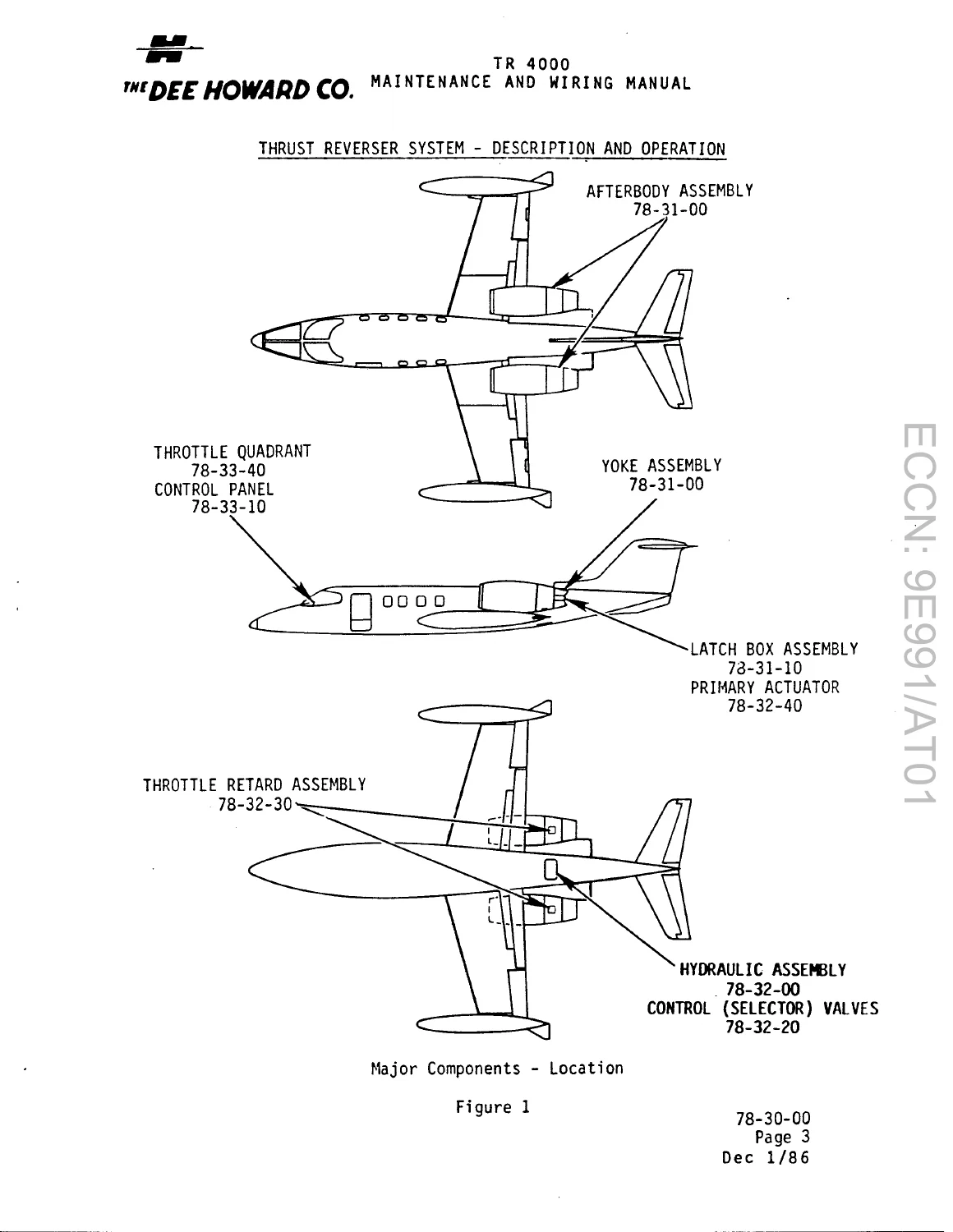
- Thrust reverser assembly (78-31): yoke, afterbody, exhaust nozzle, inner fan duct, latch box, latch plates, and reverser doors
- Hydraulic system (78-32): accumulator, check valve, selector valves, pressure indicator, throttle retard assemblies, primary actuators, and latch actuators
- Electrical system (78-33): control panel, relay boxes, terminal boards, latch monitoring switches, and full deploy switches
- Throttle quadrant (78-34): piggyback levers, idle switches, stow/deploy switches, lock-out solenoid assembly, and maximum reverse stops
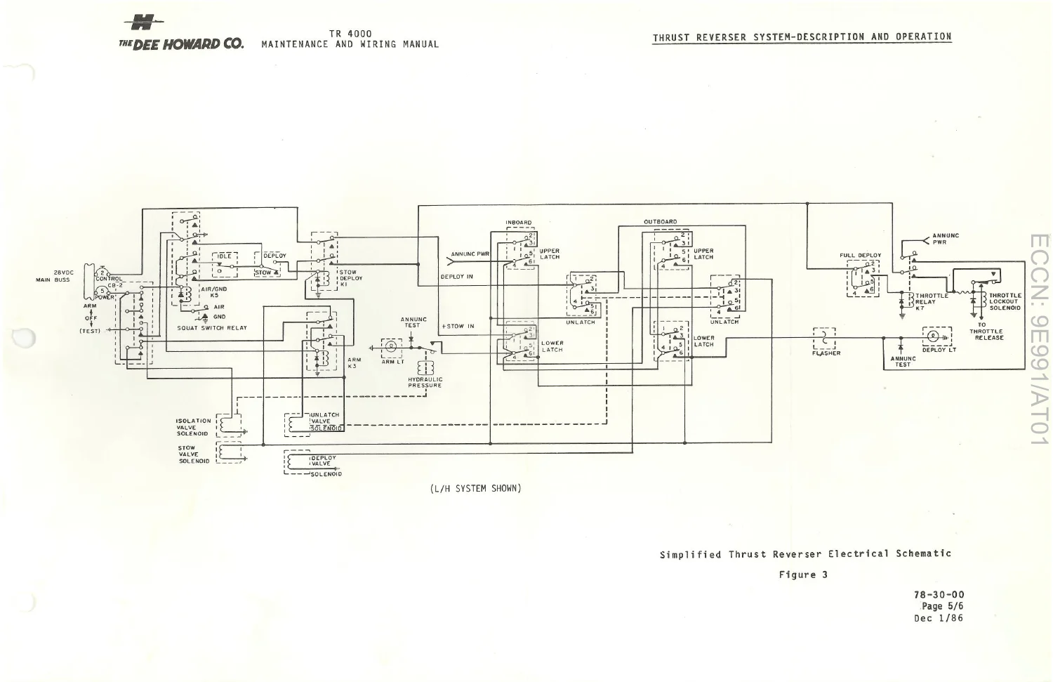
System logic is shown from ARM through overstow, unlatch, deploy, and stow. The airplane can be armed only on the ground with the power levers at idle. Stow pressure first drives the doors into overstow so the latch actuators can release the latches; deploy pressure then opens the doors and the lock-out solenoid allows increased RPM. Returning the levers to stow reverses that sequence until the spring-loaded latches close and exhaust-gas pressure plus springs return the doors to the faired position.
IMAGES PREVIEW
Chapters Covered
- 78-30-00 Thrust Reverser System — description and operation; troubleshooting; pinning; servicing; adjustment/test; inspection/check; cleaning/painting
- 78-31-00 Thrust Reverser Assembly — removal/installation; latch-plate and door adjustment; latch plate and latch wear limits
- 78-31-10 Latch Box Assembly — removal/installation; adjustment/test
- 78-32-00 Thrust Reverser Hydraulic System — servicing
- 78-32-10 Thrust Reverser Accumulator — servicing; removal/installation
- 78-32-20 Selector Valve — removal/installation
- 78-32-30 Throttle Retard Assembly — removal/installation; disassembly; assembly; adjustment/test
- 78-32-40 Primary Actuator — removal/installation
- 78-32-50 Latch Actuator — removal/installation
- 78-33-00 Electrical System — component locations; LH and RH wiring diagrams; alternate wiring and connector wiring
- 78-33-10 Control Panel — removal/installation
- 78-33-20 Relay Box — removal/installation
- 78-33-30 Terminal Board — removal/installation
- 78-33-40 Latch Monitoring Switches — removal/installation; adjustment/test
- 78-33-50 Full Deploy Switch — removal/installation; adjustment/test
- 78-34-00 Throttle Quadrant Assembly — removal/installation; maximum reverse stop; throttle quadrant width inspection
- 78-34-10 Idle Switch — removal/installation; adjustment/test
- 78-34-20 Stow/Deploy Switch — removal/installation; adjustment/test
- 78-34-30 Throttle Lock-Out Solenoid Assembly — removal/installation; adjustment/test
Taken as a whole, the supplement walks a line mechanic from a dark ARM light or a door that will not leave overstow all the way through pinning the unit for dispatch, charging the dedicated accumulator, running the full electrical/hydraulic operational test, and completing the hour-based inspection cards that coincide with airframe and powerplant checks.
Troubleshooting and Ground Checks
Fault isolation is written in Problem / Cause / Corrective Action order and is performed with engines static, external electrical power on, and the thrust-reverser accumulator charged to 1250–1500 psi. Typical cockpit symptoms covered include no ARM annunciator, doors that will not overstow, latches that pull without overstow, doors hung on fairings or Z-channel seals, a vibrating or chattering lock-out solenoid, a reverser that stays in overstow with a flashing deploy light, unexplained ARM illumination, accumulator air-charge loss, and hydraulic pressure that bleeds down to charge pressure. Corrective actions send the technician to the squat-switch relay circuit, idle switch, K-3/K-5 relays, stow/deploy switch, unlatch and stow solenoids in the selector valve, overstow stop-bolt clearance, and the pressure switch on the selector valve.
Inspection Intervals and Service Data
Temporary Revision 78-3 updates the inner-fan-duct channel-assembly inspection and the hour cards. Checks are grouped at 150–200, 300–400, 600–800, 1200–1400, and 2400–2600 hours, plus an MPI interval of 1400 hours on -2B engines and 2100 hours on -2C engines. Tasks include wire-harness and seal condition, hydraulic-line routing, exhaust-nozzle cracks, latch-box springs, control-panel markings, yoke and door-link corrosion, bushing wear (0.063 in. bushing thickness, maximum allowable wear 0.032 in.), latch and latch-plate wear against Figures 601/602, intumescent paint on Kits 002-014 afterbodies, pylon-skin fasteners, actuator leaks, and fluorescent penetrant inspection of door pivot brackets and link arms to ASTM E1417 / MIL-STD-1907 Grade A.
Ground-support items called out in the text include a 28 V DC electrical ground power unit, a hydraulic ground power unit and service cart using MIL-H-5606, deploy safety bracket P/N 4953002-1, and a 3/16 in. steel clevis pin 1-1/2 to 2 inches long for pinning a stowed latch box. Lock-out solenoid rigging is given as 0.20 +0.05/−0.00 in. plunger-to-housing clearance and 0.045 ± 0.005 in. switch-plunger setting. The dedicated reverser accumulator is described with a 900–1000 psi air charge that reads 1250–1500 psi when hydraulically pressurized.
Safety and Use With the Airplane Manuals
Before any work near the reversers the publication requires aircraft power off, doors pinned stowed or deployed, all four reverser circuit breakers pulled and collared, and both selector-valve electrical connectors disconnected. Inspection work starts only after the aircraft and TR hydraulic systems are depressurized. A deployed unit can be stowed by turning ARM off, advancing a power lever from idle, or pulling the power or squat-switch circuit breaker. Binding throttle-cable complaints are referred to Gates Learjet Maintenance Manual Chapter 76-10-00, and aircraft hydraulic-accumulator servicing is referred to Chapter 12-10-02. Those cross-references are why this Learjet 31 31A 35 35A 36 36A TR4000 thrust reverser maintenance manual supplement is used as a companion book, not as a stand-alone airframe manual.
Get the Procedures You Need
With the NORDAM TR4000 Thrust Reverser Maintenance Manual Supplement for Learjet 31 31A 35 35A 36 36A on the bench you can pin a unit for flight, charge and leak-check the reverser accumulator, run the ARM/TEST and deploy/stow operational sequence, isolate a failed idle switch or selector-valve solenoid, replace latch boxes, actuators, and throttle-quadrant hardware, and sign off the hour-based structural and pad-wear inspections that keep the clamshell doors airworthy. Using the printed overstow, latch-wear, bushing, and solenoid clearances avoids doors that hang on fairings or latches that never clear the plates. After purchase the file is delivered instantly as a PDF you can open on any device and print for the hangar or the road kit—no shipping wait and no extra hardware required.
Reviews
There are no reviews yet.