Oki C5500/C5800/C6100 Color Printer Service Manual PDF
Original price was: $95.00.$19.95Current price is: $19.95.
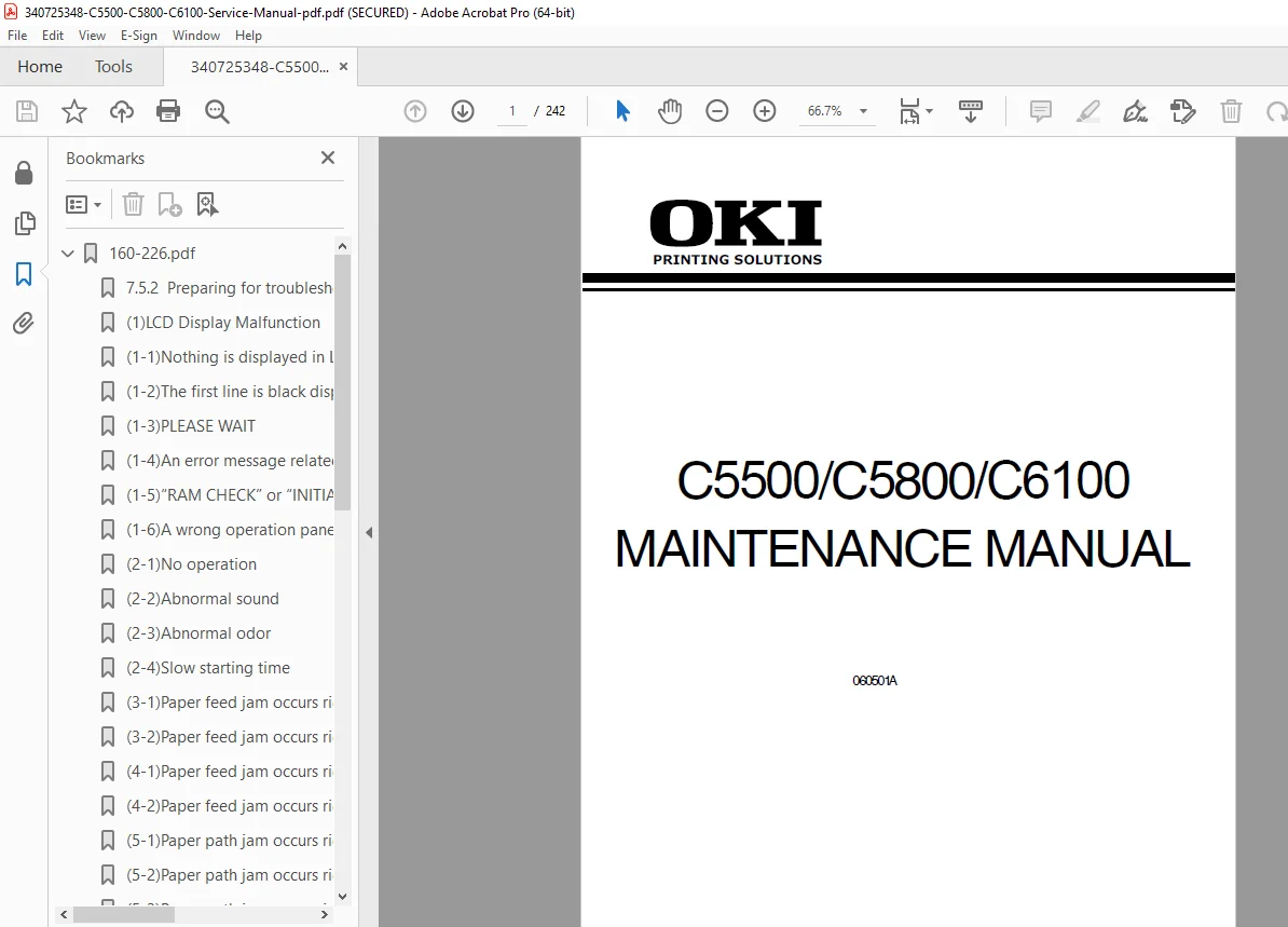
Official Oki Data maintenance manual for C5500, C5800, and C6100 color LED laser printers. This comprehensive 242-page technical guide covers complete service procedures, parts replacement, troubleshooting, and maintenance for these professional color printers. Includes detailed electrophotographic process explanations, component diagrams, error code diagnostics, image quality troubleshooting, and electrical schematics. Essential for printer technicians, IT professionals, and service centers maintaining Oki color LED printing equipment.
Description
Oki C5500/C5800/C6100 Color Printer Service Manual Complete Guide PDF DOWNLOAD
DESCRIPTION
Official Service Manual for Oki Data Color LED Laser Printers
This is the complete official Oki Data maintenance manual for the C5500, C5800, and C6100 series professional color LED laser printers. This comprehensive technical manual provides detailed service procedures, troubleshooting diagnostics, and maintenance instructions specifically designed for authorized service personnel and experienced printer technicians. Whether you’re maintaining office equipment, running a repair center, or managing IT infrastructure, this manual is your essential resource for keeping these high-performance color printers operating at peak efficiency.
📋 FILE DETAILS
- Manual Title: C5500/C5800/C6100 Maintenance Manual
- Document Number: 43085101TH Rev.1
- Manufacturer: Oki Data Corporation
- Release Date: May 1, 2006 (Document Revision 1)
- Models Covered:
- Oki C5500, C5600, C5700
- Oki C5800, C5800 (CHN), C5900, C5900dn (CHN)
- Oki C6100
- Manual Format: PDF (searchable, optimized)
- Page Count: 242 pages
- File Size: ~7.2 MB
- PDF Quality: Excellent – official manufacturer documentation with clear diagrams
🖨️ PRINTER MODELS SPECIFICATIONS
Print Speed Variants:
- C6100: 32 ppm mono / 26 ppm color
- C5800/C5900: 32 ppm mono / 26 ppm color
- C5600: 28 ppm mono / 24 ppm color
- C5500/C5700: 24 ppm mono / 20 ppm color
Key Technical Features:
- Technology: LED (Light Emitting Diode) color printing
- Resolution: True 600×1200 dpi (C6100/C5800) / 600×600 dpi (C5500)
- Processor: PowerPC 405 (200MHz) or PowerPC 750CXR (500MHz)
- Memory: 64-256 MB RAM (expandable)
- Duty Cycle: Maximum 50,000 pages/month, Average 4,000 pages/month
- Printer Life: 420,000 pages or 5 years
- First Print Time: 8-11 seconds (varies by model)
- Interfaces: Hi-Speed USB, Ethernet (10/100 Base-T)
- Duplex: Standard or optional (depending on model)
📖 COMPREHENSIVE MANUAL CONTENTS
SECTION 1: CONFIGURATION (Pages 8-19)
- 1.1 System Configuration
- Complete system architecture overview
- Component hierarchy diagrams
- Data flow and control structure
- 1.2 Printer Configuration
- Physical layout and component identification
- Internal mechanical structure
- Optical system configuration
- 1.3 Composition of Optional Items
- Second tray mechanism specifications
- Duplex printing unit
- Memory expansion options (DIMM modules)
- HDD expansion capabilities
- 1.4 Specifications (Detailed)
- Print Specifications:
- Engine speed: 20-32 ppm (model dependent)
- Print width and paper handling
- First print time specifications
- Warm-up time: 45 seconds
- Physical Specifications:
- Dimensions: 435mm (W) x 621mm (D) x 340mm (H)
- Weight: Approx. 26-29 kg (with/without duplex)
- LED Head Resolution:
- 600 dpi output resolution
- True 600×1200 dpi capability (select models)
- 600x600x4 level gradation
- Power Specifications:
- Input: 110-127VAC or 220-240VAC
- Power save mode: 15-17W
- Normal operation: 100W average, 490W typical
- Peak: 1200W
- Environmental Specifications:
- Operating: 10°C-32°C (17°C-27°C for full-color quality)
- Storage: -10°C to 43°C
- Operating humidity: 20%-80% (50%-70% optimal)
- Consumable Life:
- Image drum: 20,000-27,000 pages
- Transfer belt: 60,000 pages (auto-reset counter)
- Fuser unit: 60,000 pages (auto-reset counter)
- Toner cartridges: 1,500-6,000 pages (depending on type)
- Paper Handling:
- 1st tray: 300 sheets (70g/m²)
- 2nd tray (optional): 530 sheets (70g/m²)
- Multi-purpose tray: 100 sheets or 50 OHP sheets
- Output: 250 sheets face-down / 100 sheets face-up
- Paper sizes: A4, A5, A6, B5, Letter, Legal, Executive, Custom
- Paper weight: 64-203 gsm (depending on tray)
- Print Specifications:
- 1.5 Interface Specifications
- USB 2.0 Hi-Speed specifications and pinouts
- Network (Ethernet) specifications
- TCP/IP, IPv4/IPv6 protocol support
- Connector diagrams and cable requirements
SECTION 2: EXPLANATION OF OPERATION (Pages 20-34)
- 2.1 Electrophotographic Processing Mechanism
- 7-Step LED Printing Process:
- Charging: OPC drum surface charging via charging roller
- Exposure: LED head creates electrostatic latent image
- Development: Toner adheres to latent image
- Transfer: Toner image transferred to paper
- Drum Cleaning: Residual toner removal
- Electricity Removal: Charge neutralization
- Belt Cleaning: Transfer belt cleaning
- Detailed diagrams of each process step
- Voltage specifications for each stage
- Toner particle behavior and electrostatic principles
- LED head operation and light exposure process
- 7-Step LED Printing Process:
- 2.2 Printing Process
- Complete paper path diagrams
- Multi-color registration process
- Four-pass color printing sequence (YMCK)
- Transfer belt operation
- Fuser unit heat and pressure application
- Duplex printing mechanism (if equipped)
- Paper feed timing and synchronization
SECTION 3: INSTALLATION (Pages 35-63)
- 3.1 Cautions and Safety Precautions
- Static electricity precautions
- Safe handling procedures
- Environmental considerations
- 3.2 Unpacking Method
- Step-by-step unboxing procedures
- Protective material removal
- Component inventory checklist
- 3.3 Printer Installation Instructions
- Site preparation requirements
- Ventilation and clearance specifications
- Power supply requirements
- 3.4 Component Units and Accessories Listing
- Complete parts inventory
- Consumables identification
- Tool requirements
- 3.5 Assembling Method
- Printer Main Body Assembly
- Protective tape and shipping material removal
- Toner cartridge installation procedures
- Image drum unit installation
- Paper tray installation
- Power Cable Connection
- Grounding requirements
- Voltage selection (where applicable)
- Optional Items Installation
- Second tray mechanism installation
- Duplex unit installation
- Memory (DIMM) expansion procedures
- HDD installation (if applicable)
- Confirmation of Optional Item Recognition
- Menu navigation for hardware detection
- Configuration verification procedures
- Printer Main Body Assembly
- 3.6 Menu Map Print
- Complete printer settings printout
- Configuration documentation procedures
- 3.7 Connection Methods
- USB connection setup
- Network (Ethernet) connection
- IP address configuration
- Driver installation guidance
- 3.8 Confirmation of Paper Used by User
- Paper type compatibility verification
- Media weight testing procedures
SECTION 4: REPLACEMENT OF PARTS (Pages 64-107)
Complete step-by-step parts replacement procedures with detailed diagrams:
- 4.1 Precautions on Parts Replacement
- ESD (Electrostatic Discharge) protection
- Proper handling techniques
- Safety warnings
- 4.2 Detailed Part Replacement Methods:
- Covers and External Components:
- Left side cover removal/installation
- Right side cover removal/installation
- Face-Up Tray replacement
- Rear cover removal/installation
- Top cover assembly replacement
- Front cover removal/installation
- Optical Components:
- LED Assembly (LED Assy) replacement
- LED Assembly springs replacement
- LED head serial number procedures
- Circuit Boards (PCBs):
- Control PCB replacement
- Print Engine Controller PCB replacement
- Board PRP replacement
- Board PRY replacement
- Board PRZ replacement
- Board RSF replacement
- High-Voltage Power Supply Board replacement
- Power and Motor Components:
- Low-Voltage Power Supply replacement
- Low-Voltage Fan replacement
- Fuser Fan replacement
- Belt Motor replacement
- Hopping Motor replacement
- Fuser Motor replacement
- Lift-Up Motor replacement
- Paper Feed Components:
- Multi-Purpose Tray (MPT) Assembly
- Feeder Unit replacement
- MPT Hopping Roller replacement
- Frame Assembly Separator
- Feed Roller replacement
- Paper-End Sensor replacement
- Paper Exit Components:
- Guide Eject Assembly replacement
- Shaft Eject Assembly (Fuser/Feed) replacement
- Eject Sensor replacement
- Imaging Components:
- Fuser Unit complete replacement procedure
- Belt Unit replacement
- Color Register Assembly replacement
- Switches and Sensors:
- Cover-Open Switch replacement
- Solenoid replacement
- Control Panel:
- Controller Panel Assembly replacement
- Top Cover Handle replacement
- Covers and External Components:
- 4.3 Lubricating Points
- Comprehensive lubrication diagram
- Grease type specifications
- Application points and quantities
- Lubrication schedule recommendations
SECTION 5: MAINTENANCE MENUS (Pages 108-154)
- 5.1 System Maintenance Menu (Service Personnel)
- Access procedures for technician-level menus
- Advanced configuration options
- Factory default settings
- Service mode activation
- 5.2 Maintenance Utility
- Software-based diagnostic tools
- Configuration backup and restore
- Firmware update procedures
- 5.3 User’s Maintenance Menu Functions
- Operator Panel Navigation:
- LCD display structure (16 characters x 2 lines)
- Button functions and combinations
- LED indicators (Green/Amber status lights)
- Self-Diagnostic Mode (Level 1):
- Activation/deactivation procedures
- Switch Scan Test: Verifies all buttons and sensors
- Motor Clutch Test: Tests all motors and mechanical components
- Test Print Functions:
- Nozzle check patterns
- Color alignment patterns
- Density adjustment patterns
- Configuration page printing
- Color Registration Adjustment Test: Fine-tuning color alignment
- Print Density Adjustment Test: Optimizing print darkness
- Consumable Part Counters: Displays usage statistics
- Printed Page Counters: Total and per-color page counts
- Factory/Shipping Mode Switching
- LED Head Serial Number Display
- Panel Indication Details: Complete error code reference
- Various Print Types:
- Network configuration page
- Font sample pages
- Demo pages
- Key Functions at Power-On:
- Special boot modes
- Reset procedures
- Default restoration
- Operator Panel Navigation:
- 5.4 Setup After Parts Replacement
- Engine Control PCB Replacement Precautions
- EEPROM Setup After SP1/TBH PCB Replacement
- CU Serial Number Setup Procedures
- Destination Configuration Setup
- 5.5 Manual Print Density Adjustment
- Manual calibration procedures
- Test pattern interpretation
- Adjustment value entry methods
SECTION 6: PERIODICAL MAINTENANCE (Pages 155-159)
- 6.1 Recommended Replacement Parts
- Consumables replacement schedule
- Preventive maintenance parts list
- Service intervals
- 6.2 General Cleaning Procedures
- Routine cleaning schedule
- Approved cleaning materials
- Safety precautions
- 6.3 Cleaning of LED Lens Array
- Critical optical component cleaning
- Special cleaning procedures
- Tools and materials required
- Print quality impact
- 6.4 Cleaning of Pickup Rollers
- Paper feed roller maintenance
- Cleaning frequency
- Replacement criteria
- 6.5 Internal Printer Cleaning
- Paper path cleaning
- Corona wire cleaning (if applicable)
- Dust and debris removal
- Toner residue cleanup
SECTION 7: TROUBLESHOOTING PROCEDURES (Pages 160-226)
Comprehensive diagnostic and repair procedures:
- 7.1 Precautions Prior to Repair
- Safety considerations
- ESD protection requirements
- Power-down procedures
- 7.2 Items to Check Prior to Image Quality Issues
- Paper type verification
- Environmental conditions
- Consumable status
- Driver settings verification
- 7.3 Precautions for Image Quality Issues
- Safe troubleshooting procedures
- Test pattern usage
- Documentation requirements
- 7.4 Preparations for Troubleshooting
- Required tools and materials
- Test page printing
- Log file access
- 7.5 Comprehensive Troubleshooting Methods:
- 7.5.1 Complete LCD Message List with Error Codes:
- Paper jam errors (370-391 series)
- Fuser errors (170-177 series)
- Motor/Fan errors (051, 120, 127)
- Service call codes (140-143, 150-155)
- Toner cartridge errors (540-543)
- LED head errors (131-134)
- Paper size errors (400 series)
- Environmental errors (123 – Dew condensation)
- Each error includes: Cause, Check points, Resolution steps
- 7.5.2 Detailed Troubleshooting Procedures:
- LCD Display Malfunction: Complete diagnostic flowchart
- Irregular Operation After Power-On: Startup sequence checks
- Paper Feed Jams:
- Error 391: 1st Tray jam diagnosis
- Error 390: Multi-purpose Tray jam diagnosis
- Paper Path Jams:
- Error 381: Internal path jam locations
- Error 382: Paper exit jam resolution
- Duplex Print Jams: Errors 370-373, 383
- Paper Size Errors: Error 400 troubleshooting
- ID Unit Up/Down Errors: Service Calls 140-143
- Fuser Unit Errors: Errors 170-177 (temperature-related)
- Motor/Fan Errors: Component testing procedures
- Slow Print Speed: Performance degradation diagnosis
- Option Unit Not Recognized: Detection troubleshooting
- LED Head Not Recognized: Errors 131-134
- Toner Cartridge Not Recognized: Errors 540-543
- Fuse Cutout Errors: Errors 150-155
- Dew Condensation Errors: Error 123
- 7.5.3 Image Quality Problem Troubleshooting:
- Color Totally Pale: Toner, drum, exposure issues
- Background Dirty: Drum cleaning, charge issues
- Blank Print: Complete diagnostic flowchart
- Vertical Lines: Drum, LED head, cleaning blade issues
- Cyclic Print Trouble: Component rotation measurements
- Color Registration Problems: Alignment procedures
- Solid Black Print: Electrical and exposure diagnostics
- 7.5.4 Actions After Forced HDD/Flash Initialization
- Data recovery procedures
- Reconfiguration requirements
- 7.5.5 Network Troubleshooting
- TCP/IP configuration issues
- Connectivity diagnostics
- Protocol-specific problems
- 7.5.1 Complete LCD Message List with Error Codes:
- 7.6 Fuse Checking Procedures
- Fuse location diagrams
- Testing methods
- Replacement specifications
SECTION 8: CONNECTION DIAGRAMS (Pages 227-242)
- 8.1 Resistance Value Checks
- Component resistance specifications
- Testing procedures
- Acceptable ranges
- Fault diagnosis based on readings
- 8.2 Component Layout
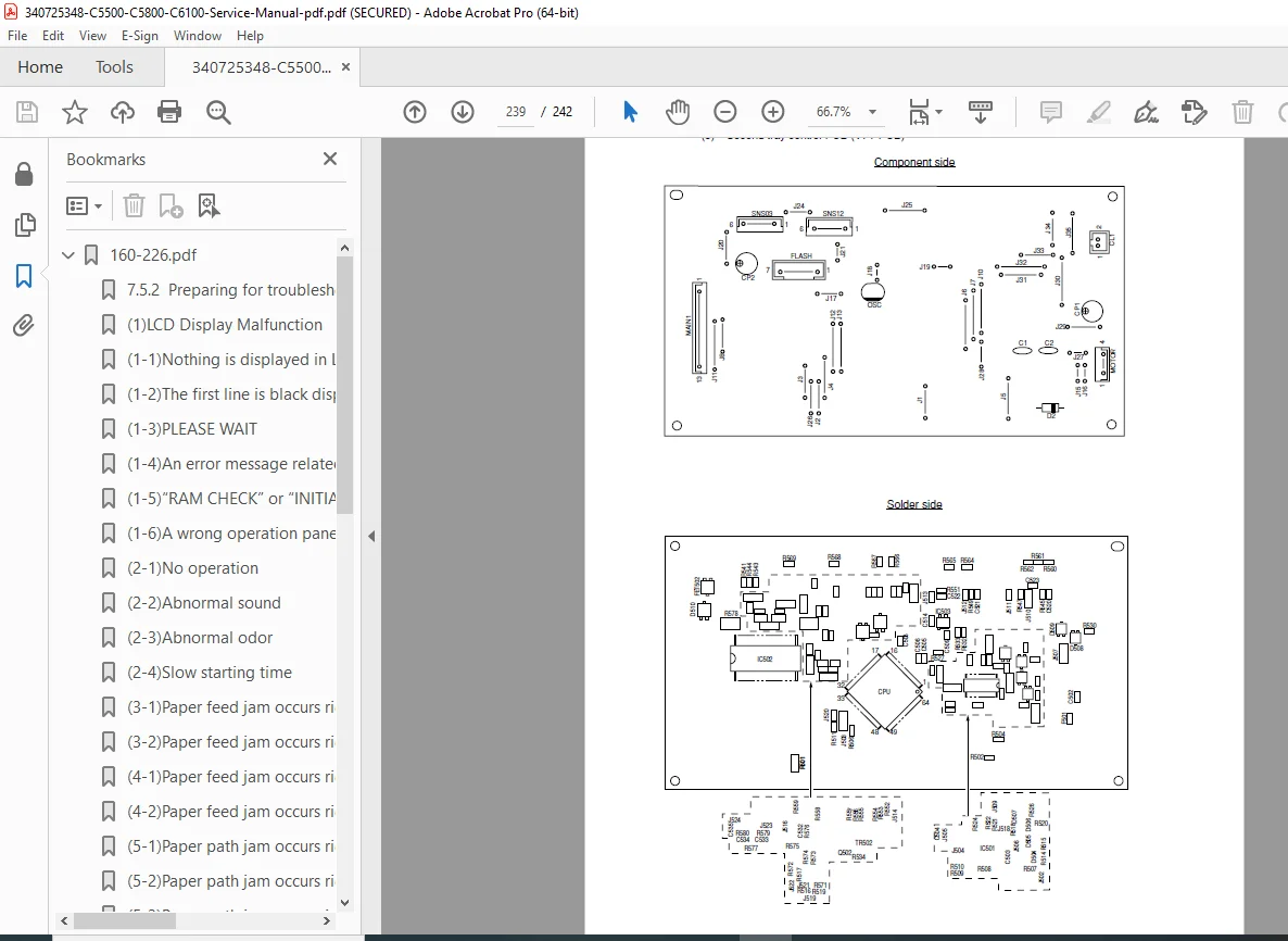
- Complete electrical system diagrams
- PCB component location maps
- Wiring harness routing diagrams
- Connector pinout diagrams
- Motor and sensor connections
- Power distribution schematics
- Signal flow diagrams
🔧 PERFECT FOR:
✅ Authorized Service Technicians – Complete OEM repair procedures ✅ Printer Repair Centers – Professional diagnostic and repair resource ✅ IT Service Departments – Maintain office printing infrastructure ✅ Field Service Engineers – On-site troubleshooting reference ✅ Technical Support Personnel – Remote diagnostics and guidance ✅ Refurbishment Companies – Restoration and parts replacement ✅ Electronics Technicians – Circuit-level repair information ✅ Managed Print Service Providers – Fleet maintenance resource
💡 KEY FEATURES OF THIS MANUAL:
- LED Technology Focus: Specialized coverage of LED printing technology vs. traditional laser
- Multiple Model Coverage: Single manual covers entire C5500/C5800/C6100 series
- Complete Error Code Database: Every error message documented with solutions
- Image Quality Diagnostics: Systematic approach to print quality problems
- Parts Replacement Procedures: Step-by-step with detailed photographs
- Electrical Schematics: Complete wiring diagrams and component layouts
- Lubrication Guide: Critical maintenance points identified
- Self-Diagnostic Modes: Access hidden service menus and tests
- Consumable Counter Reset: Procedures for all replaceable components
- Network Configuration: Complete TCP/IP and network setup guidance
🎯 CRITICAL TECHNICAL COVERAGE:
- Electrophotographic Process: Complete LED exposure and development cycle
- Color Registration: Four-pass CMYK alignment procedures
- Transfer Belt System: Belt unit operation and maintenance
- Fuser Technology: Heat roller system operation and troubleshooting
- LED Head Operation: Digital exposure system vs. laser scanning
- Paper Path Mechanics: Complete feed-to-exit paper handling
- High-Voltage Systems: Charging and transfer voltage specifications
- Motor Control: Belt motor, fuser motor, feed motor diagnostics
- Sensor Systems: Paper detection, temperature, position sensors
- Network Integration: Embedded print server configuration
📐 SPECIFICATIONS QUICK REFERENCE:
- Print Technology: 4-pass LED color printing
- LED Head Resolution: 600 dpi (up to 1200 dpi enhanced)
- Print Speed: 20-32 ppm (model dependent)
- Monthly Duty Cycle: Up to 50,000 pages maximum
- Paper Capacity: Up to 830 sheets (with optional trays)
- Memory: 64-256 MB (expandable to 512 MB on select models)
- Connectivity: USB 2.0 Hi-Speed, 10/100 Ethernet
- Supported OS: Windows, Mac, Linux (via PCL/PostScript)
- Emulations: PCL5c/PCL XL, PostScript 3, SIDM
⚡ INSTANT DOWNLOAD – Begin servicing Oki C5500/C5800/C6100 color LED printers immediately! This official maintenance manual provides complete factory-authorized procedures for diagnostics, repair, and maintenance of these professional color printing systems. Essential for reducing downtime and maintaining optimal print quality!
Justification:
- 242 pages of official OEM technical documentation
- Covers 3 major printer series (C5500/C5800/C6100) – 9 model variants
- Professional/commercial color LED printers ($1,000-$3,000+ devices)
- Complete error code database with solutions
- Detailed parts replacement procedures with diagrams
- Critical for service centers and IT departments
- Electrical schematics and component-level repair info
- Network configuration and protocol troubleshooting
- Reduces service call costs significantly
- Similar professional printer service manuals sell for $40-$80
- Essential for businesses relying on color printing
This service manual is an invaluable resource for maintaining and repairing Oki C5500/C5800/C6100 series color LED printers. Download now and have complete factory-authorized service documentation for these professional printing systems!