
OM XRS14ac XRS16ac XRS20ac Series 115-12 Tough Terrain Reach Truck Workshop Manual
Original price was: $34.95.$21.95Current price is: $21.95.
Complete OM workshop literature for the XRS14ac, XRS16ac and XRS20ac Series 115-12 Tough Terrain reach trucks – service plans, overhaul procedures, torque values, wiring and hydraulic diagrams, and full traction, hydraulic, steering and display diagnostic code tables. 224-page English PDF, Edition 01/2010.
Description
The OM XRS14ac XRS16ac XRS20ac Series 115-12 Tough Terrain Reach Truck Workshop Manual is the full workshop literature issued by OM Carrelli Elevatori S.p.A. for the AC-powered 115-12 Tough Terrain reach truck family. It is written for the people who actually maintain these machines: mechanics, workshop supervisors and service engineers who need the correct procedure, the correct torque and the correct fault code rather than a generic guess. The document is Edition 01/2010, published under number 115 801 21 05 EN, and runs to 224 pages of procedure text, illustrations, exploded views and circuit diagrams.
File Details
- Manual type: Workshop literature – service, repair, maintenance and diagnostics
- Brand: OM Carrelli Elevatori S.p.A.
- Models covered: XRS14ac, XRS16ac, XRS20ac (Series 115-12 Tough Terrain)
- Language: English
- File format: PDF
- Page count: 224
- Document number: 115 801 21 05 EN
- Edition: 01/2010 – First Edition
Chapters Covered
- 0 Product Information – maintenance safety guidelines, handling lubricants, covers and cowlings, emergency lower, emergency steering and parking brake release, securing for transportation, slinging the truck, towing procedure, jacking the truck, mast unit
- Service Plans – 50 h, 1000 h, 2000 h, 5000 h and 10000 h schedules, recommended lubricants, standard torques, non-standard torques, special tools
- Diagnostics – overview and CAN bus connection, diagnostic connector, Canbox serial and USB, software update for Canbox, diagnostic software, traction diagnostic codes, hydraulic diagnostic codes, steering diagnostic codes, display diagnostic codes, LAC traction diagnostic codes, LAC hydraulic diagnostic codes
- 1 Motor – traction motor removal and installation, cooling fan, speed sensor and temperature sensor
- 2 Axles – mechanical drive axle, drive wheel, rubber suspension spring
- 3 Chassis, Bodywork and Fittings – chassis, bump stop adjustment, covers and panelling, steering binnacle, operator’s console, operator’s seat, seat assembly, battery carrier and its lubrication
- 4 Undercarriage – electrical steering (steering wheel potentiometer, drive wheel position potentiometer, steering motor), wheels and tyres (load wheels), brake installation (traction motor brake, load wheel brakes)
- 5 Controls – drive and brake controls, accelerator and brake pedals, master cylinder, operating elements, joysticks
- 6 Electric/Electronic – battery and accessories, battery lock sensor, safety precautions, EMC, AC control operating principle, connector locations, fuses, emergency isolator, 13 volt power supply, control module (LDC 61), connector X13 pin designations, charge resistor module, electrical control for traction, hydraulics, steering and display
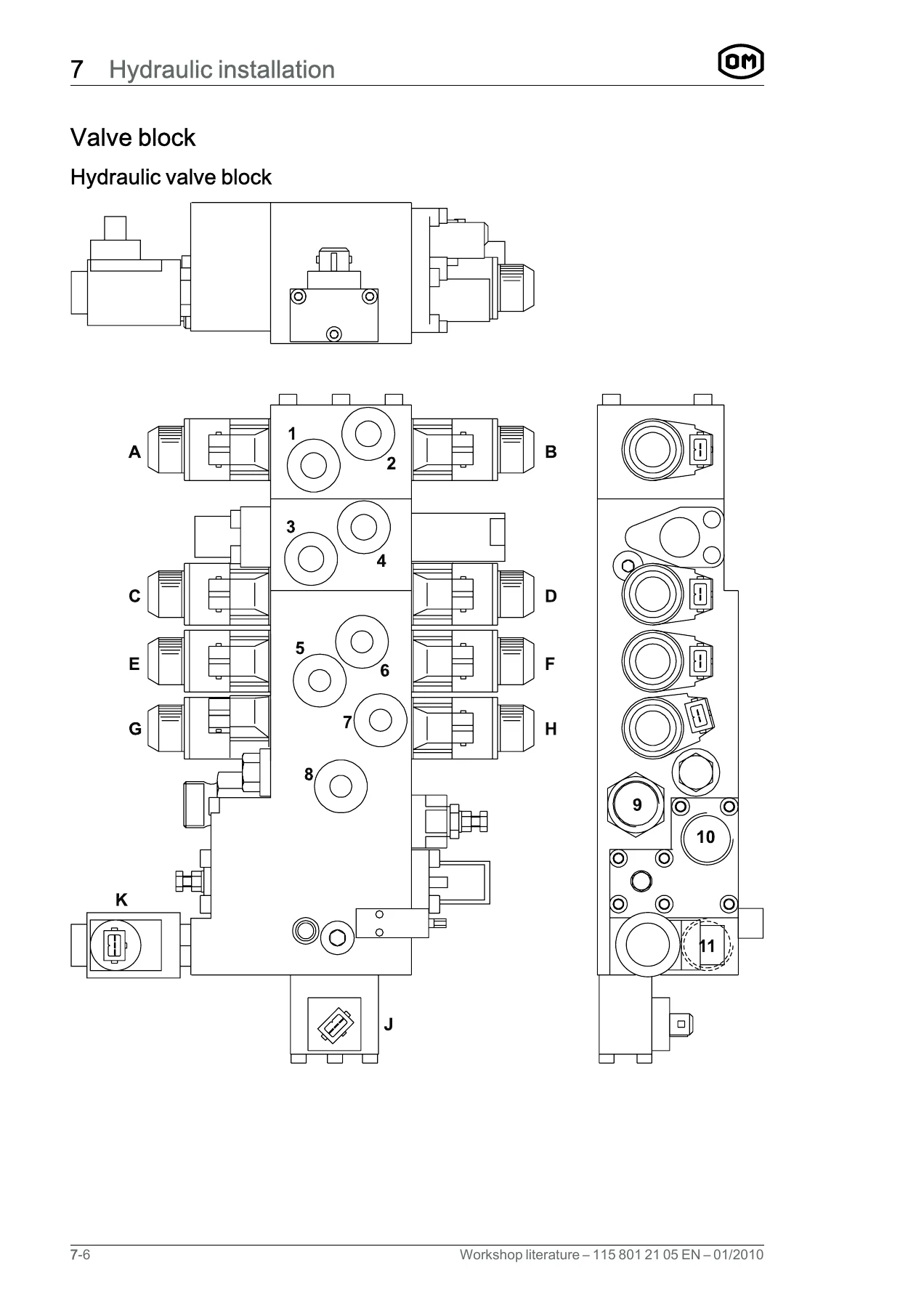
- 7 Hydraulic Installation – operating hydraulics, changing the hydraulic oil and suction filter, hydraulic motor and pump assembly, hydraulic valve block
- 8 Load Lift System – mast unit, mast, reach cylinder, tilt cylinders, load support, sideshift unit, forks and fork inspection limits
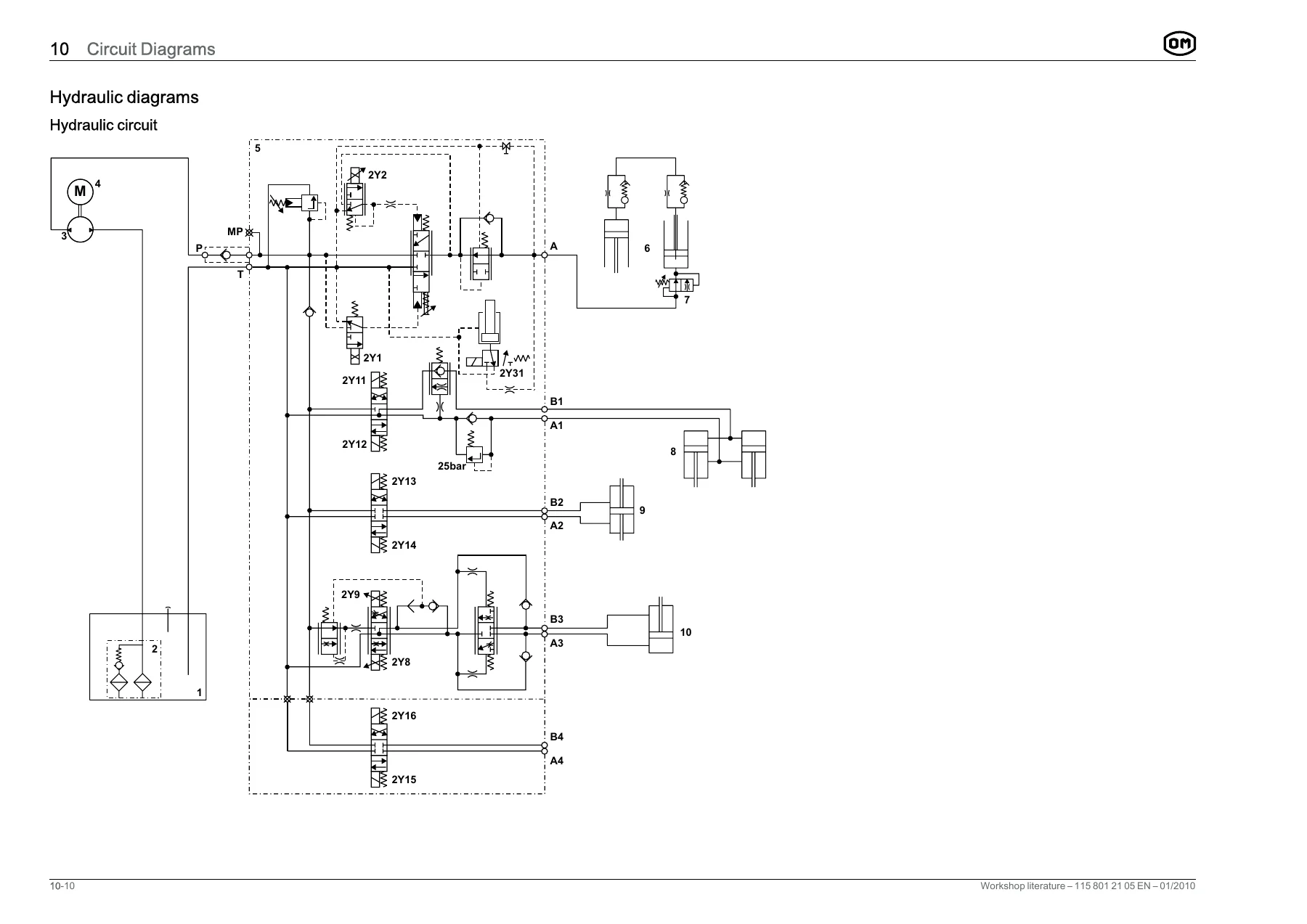
- 10 Circuit Diagrams – electric diagram (standard) 115 802 60 14, electric diagram (variable electric brake) 115 802 60 09, hydraulic circuit
Read end to end, the manual moves from general workshop safety and the recommended lubricant and torque tables, through every major assembly on the truck, and finishes with the electrical and hydraulic schematics that tie the whole machine together. Each mechanical chapter follows the same practical rhythm – safe shutdown, component removal, inspection and wear limits, then reinstallation with the tightening figures that matter. The electrical chapters go further than most workshop literature: they explain how the AC control principle actually produces a variable-frequency, variable-voltage supply to the traction and pump motors, then map every controller pin, connector location and valve output so a fault can be traced rather than replaced blindly. The diagnostic code lists alone cover several hundred numbered entries across the traction, hydraulic, steering, display and LAC controllers.
Diagnostics and Fault Codes
The diagnostic chapter is organised so that a code number immediately tells you how serious the problem is. Codes 1 to 99 are information codes – interlock status rather than faults, and they are not stored in the controller history. Codes 100 to 199 are warnings: the truck keeps working, but the event is logged. Codes 200 to 999 are faults that change how the truck behaves, up to and including a shutdown, and every one of them is stored. This structure applies to the traction, hydraulic, steering and display code tables, and again to the LAC traction and LAC hydraulic controller tables, so the same reading discipline works across the whole machine. The Canbox connection, diagnostic connector location and the software update routine for the Canbox itself are all documented, along with the guided diagnostics, error code, parameter, input and output screens used to calibrate the accelerator, steering unit and reach limits.
Torque Values, Lubricants and Service Intervals
A full standard torque table is given for grades 4.6 through 12.9 in both coarse and fine threads, followed by non-standard torques listed section by section. These include the gearbox mounting plate at 700 Nm, the drive wheel nut at 195 Nm, the rubber compression spring centre screw at 300 Nm, the mast-to-reach-carriage bottom fixing at 600 Nm, reach leg stop screws at 50 Nm and the tilt cylinder pinch bolt at 46 Nm, among many others. Lubricant recommendations name the hydraulic oil grade and viscosity, the lithium-based multipurpose grease, the gear oil classification, the molybdenum disulphide steering gear grease and the brake fluid specification. The service plans set out what is checked, lubricated or replaced at 50, 1000, 2000, 5000 and 10000 hours, from drive unit suspension and wheel security through to hydraulic fluid changes and load wheel brake inspection.
Safety Procedures You Will Not Find Elsewhere
The manual is unusually specific about how to make the truck safe before you touch it. It explains how to discharge the steering capacitor through the horn with the battery plug disconnected, and to confirm less than 5 V between 3F1 and main negative before working on the control system. It sets out the wood block method for securing the reach frame against reaching in or out, the chain method for securing the mast, the two M6 x 55 mm screws that mechanically release the parking brake, and the procedure for moving a truck out of an aisle after a complete electrical failure. Jacking points, slinging points and lashing points are illustrated so the truck is not damaged or dropped.
Who This Workshop Manual Is For
If you service OM Series 115-12 Tough Terrain reach trucks, this is the document that lets you carry out the job properly. It supports scheduled maintenance to the 10000-hour mark, removal and refitting of the traction motor, drive wheel, steering motor, drive wheel position potentiometer, hydraulic pump and motor assembly, valve block, mast, reach cylinder and tilt cylinders, load wheel brake overhaul, fork inspection against the wear limits, and fault-finding across every controller on the CAN bus. Having the correct torque, the correct clearance and the correct code interpretation matters on a machine that lifts loads at height – a guessed figure is a risk to the operator and to the load. This workshop manual removes that guesswork.
IMAGES PREVIEW
Delivery is instant. The file is a PDF download, so there is no shipping, no waiting and no physical book to lose in the workshop. Open it on a laptop, tablet or phone, print the pages you need for the job at hand, and keep the electrical and hydraulic diagrams beside the truck while you work.

Reviews
There are no reviews yet.