Perkins 1104D Industrial Engines Disassembly & Assembly Manual – PDF DOWNLOAD
Original price was: $62.95.$22.95Current price is: $22.95.
Perkins 1104D Industrial Engines Disassembly & Assembly Manual
Description
Perkins 1104D Industrial Engines Disassembly & Assembly Manual
File Details:
Perkins 1104D Industrial Engines Disassembly & Assembly Manual
Language : English
Pages : 167
Size : 2.51 MB
Downloadable : Yes
Format : PDF
PERKINS 1104D INDUSTRIAL ENGINES DISASSEMBLY & ASSEMBLY MANUAL – PDF DOWNLOAD:
Image Preview:
Table Of Contents:
Perkins 1104D Industrial Engines Disassembly & Assembly Manual
Disassembly and Assembly Section
Fuel Priming Pump – Remove and Install (Electric
Fuel Priming Pump) ………………………………………. 5
Fuel Priming Pump – Remove and Install (Manual
Priming Pump) ……………………………………………… 6
Fuel Filter Base – Remove and Install (Secondary
Fuel Filter) ……………………………………………………. 8
Fuel Transfer Pump – Remove ………………………….. 9
Fuel Transfer Pump – Install …………………………….. 11
Fuel Injection Lines – Remove ……………………….. 13
Fuel Injection Lines – Install …………………………… 14
Fuel Manifold (Rail) – Remove and Install …………. 16
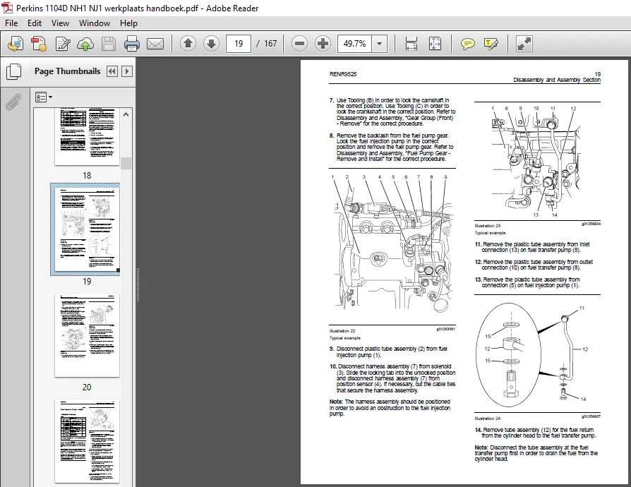
Fuel Injection Pump – Remove ………………………. 18
Fuel Injection Pump – Install ………………………….. 21
Fuel Injection Pump Gear – Remove ……………….. 24
Fuel Injection Pump Gear – Install …………………… 26
Electronic Unit Injector – Remove ……………………. 27
Electronic Unit Injector – Install ……………………….. 31
Turbocharger – Remove …………………………………. 36
Turbocharger – Install …………………………………….. 37
Wastegate Solenoid – Remove and Install ………… 38
Exhaust Manifold – Remove and Install …………… 39
Exhaust Elbow – Remove and Install ………………. 41
Inlet and Exhaust Valve Springs – Remove and
Install …………………………………………………………. 42
Inlet and Exhaust Valves – Remove and Install …. 45
Engine Oil Filter Base – Remove and Install …….. 48
Engine Oil Cooler – Remove …………………………… 49
Engine Oil Cooler – Install ………………………………. 50
Engine Oil Relief Valve – Remove and Install (Engines
with a Balancer Unit) ……………………………………. 51
Engine Oil Relief Valve – Remove and Install (Engines
Without a Balancer Unit) ………………………………. 53
Engine Oil Pump – Remove and Install (Engines
Without a Balancer Unit) ………………………………. 54
Water Pump – Remove ………………………………….. 56
Water Pump – Install ……………………………………… 57
Water Temperature Regulator – Remove and Install
………………………………………………………………….. 58
Flywheel – Remove ……………………………………….. 60
Flywheel – Install …………………………………………… 61
Crankshaft Pulley – Remove and Install (Engines
With an Automatic Belt Tensioner) …………………. 62
Crankshaft Pulley – Remove and Install (Engines
Without an Automatic Belt Tensioner) …………….. 63
Crankshaft Rear Seal – Remove ……………………… 64
Crankshaft Rear Seal – Install …………………………. 65
Crankshaft Wear Sleeve (Rear) – Remove and
Install …………………………………………………………. 66
Flywheel Housing – Remove and Install ………….. 67
Crankshaft Front Seal – Remove and Install ……… 69
Crankshaft Wear Sleeve (Front) – Remove and
Install …………………………………………………………. 70
Front Cover – Remove and Install ……………………. 72
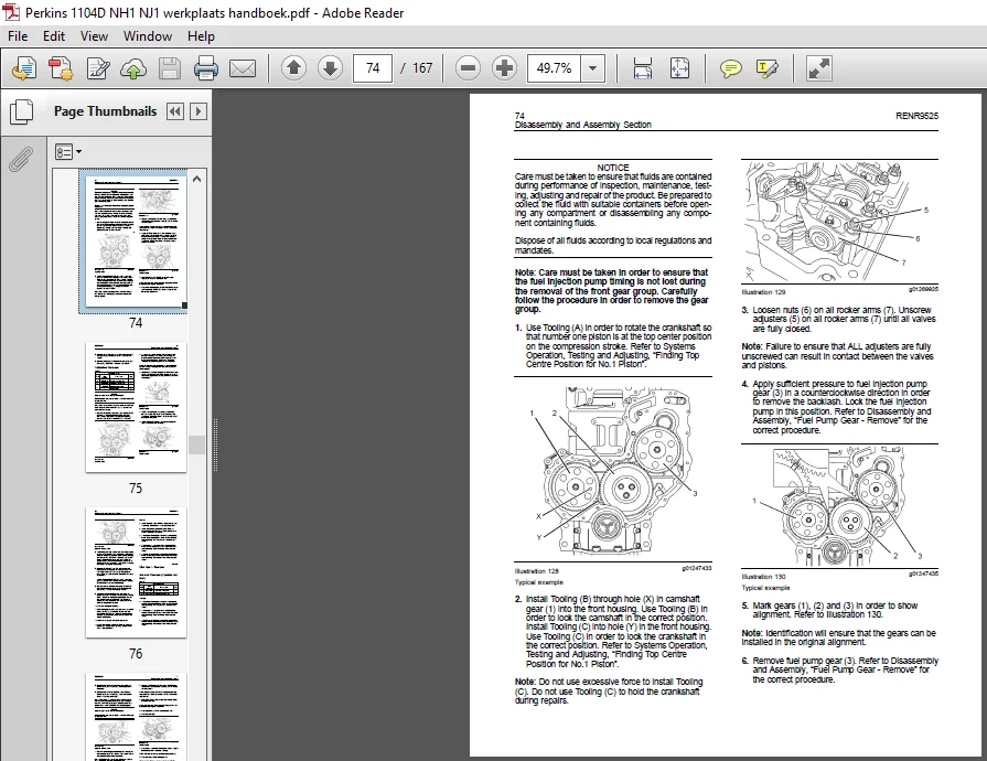
Gear Group (Front) – Remove and Install …………. 73
Idler Gear – Remove ……………………………………… 76
Idler Gear – Install …………………………………………. 79
Housing (Front) – Remove ……………………………… 81
Housing (Front) – Install …………………………………. 83
Accessory Drive – Remove and Install …………….. 85
Crankcase Breather – Remove and Install (Filtered
Breather) ……………………………………………………. 87
Crankcase Breather – Remove and Install (Unfiltered
Breather) ……………………………………………………. 88
Valve Mechanism Cover – Remove and Install ….. 88
Valve Mechanism Cover Base – Remove and
Install …………………………………………………………. 90
Rocker Shaft and Pushrod – Remove ………………. 92
Rocker Shaft – Disassemble ………………………….. 93
Rocker Shaft – Assemble ………………………………. 94
Rocker Shaft and Pushrod – Install ………………….. 95
Cylinder Head – Remove ……………………………….. 97
Cylinder Head – Install …………………………………. 100
Lifter Group – Remove and Install ………………….. 104
Camshaft – Remove and Install ……………………. 105
Camshaft Gear – Remove and Install ……………. 106
Camshaft Bearings – Remove and Install ………. 109
Engine Oil Pan – Remove and Install (Aluminum and
Pressed Steel Oil Pans) ………………………………. 110
Engine Oil Pan – Remove and Install (Cast Iron Oil
Pan) …………………………………………………………. 113
Balancer – Remove ………………………………………. 116
Balancer – Install ………………………………………….. 118
Piston Cooling Jets – Remove and Install ……….. 120
Pistons and Connecting Rods – Remove ………… 121
Pistons and Connecting Rods – Disassemble ….. 122
Pistons and Connecting Rods – Assemble ……… 124
Pistons and Connecting Rods – Install ……………. 126
Connecting Rod Bearings – Remove (Connecting
rods in position) …………………………………………. 128
Connecting Rod Bearings – Install (Connecting rods
in position) ………………………………………………… 129
Crankshaft Main Bearings – Remove and Install
(Crankshaft in position) ………………………………. 130
Crankshaft – Remove …………………………………… 135
Crankshaft – Install ………………………………………. 137
Crankshaft Timing Ring – Remove and Install …. 140
Crankshaft Gear – Remove and Install ………….. 141
Bearing Clearance – Check …………………………… 142
Crankshaft Position Sensor – Remove and
Install ……………………………………………………….. 143
Coolant Temperature Sensor – Remove and
Install ……………………………………………………….. 144
Engine Oil Pressure Sensor – Remove and Install
………………………………………………………………… 145
Position Sensor (Fuel Injection Pump) – Remove and
Install ……………………………………………………….. 147
Fuel Pressure Sensor – Remove and Install ……. 148
Boost Pressure Sensor – Remove and Install ….. 149
Inlet Air Temperature Sensor – Remove and
Install ……………………………………………………….. 150
Glow Plugs – Remove and Install ………………….. 151
V-Belts – Remove and Install (Engines Without an
Automatic Belt Tensioner ) ………………………….. 152
Alternator Belt – Remove and Install (Engines With
an Automatic Belt Tensioner) ………………………. 153
Fan – Remove and Install …………………………….. 154
Fan Drive – Remove and Install ……………………. 155
Electronic Control Module – Remove and Install .. 156
ECM Mounting Bracket – Remove and Install ….. 158
Description:
Perkins 1104D Industrial Engines Disassembly & Assembly Manual
Most accidents that involve product operation, maintenance and repair are caused by failure to observe basic safety rules or precautions.
An accident can often be avoided by recognizing potentially hazardous situations before an accident occurs.
A person must be alert to potential hazards.
This person should also have the necessary training, skills and tools to perform these functions properly.
Improper operation, lubrication, maintenance or repair of this product can be dangerous and could result in injury or death.
Do not operate or perform any lubrication, maintenance or repair on this product, until you have read and understood the operation, lubrication, maintenance and repair information.
Safety precautions and warnings are provided in this manual and on the product.
If these hazard warnings are not heeded, bodily injury or death could occur to you or to other persons.
The hazards are identified by the “Safety Alert Symbol” and followed by a “Signal Word” such as “DANGER”, “WARNING” or “CAUTION”. The Safety Alert “WARNING” label is shown below.
Please Note:
- This is the SAME exact manual used by your dealers to fix your vehicle.
- The same can be yours in the next 2-3 mins as you will be directed to the download page immediately after paying for the manual.
- Any queries / doubts regarding your purchase, please feel free to contact [email protected]
Leonidas Kamari –
SAFE & SECURE SIGHT
Clay Jase –
Good and secure way for shopping.