Description
File Details
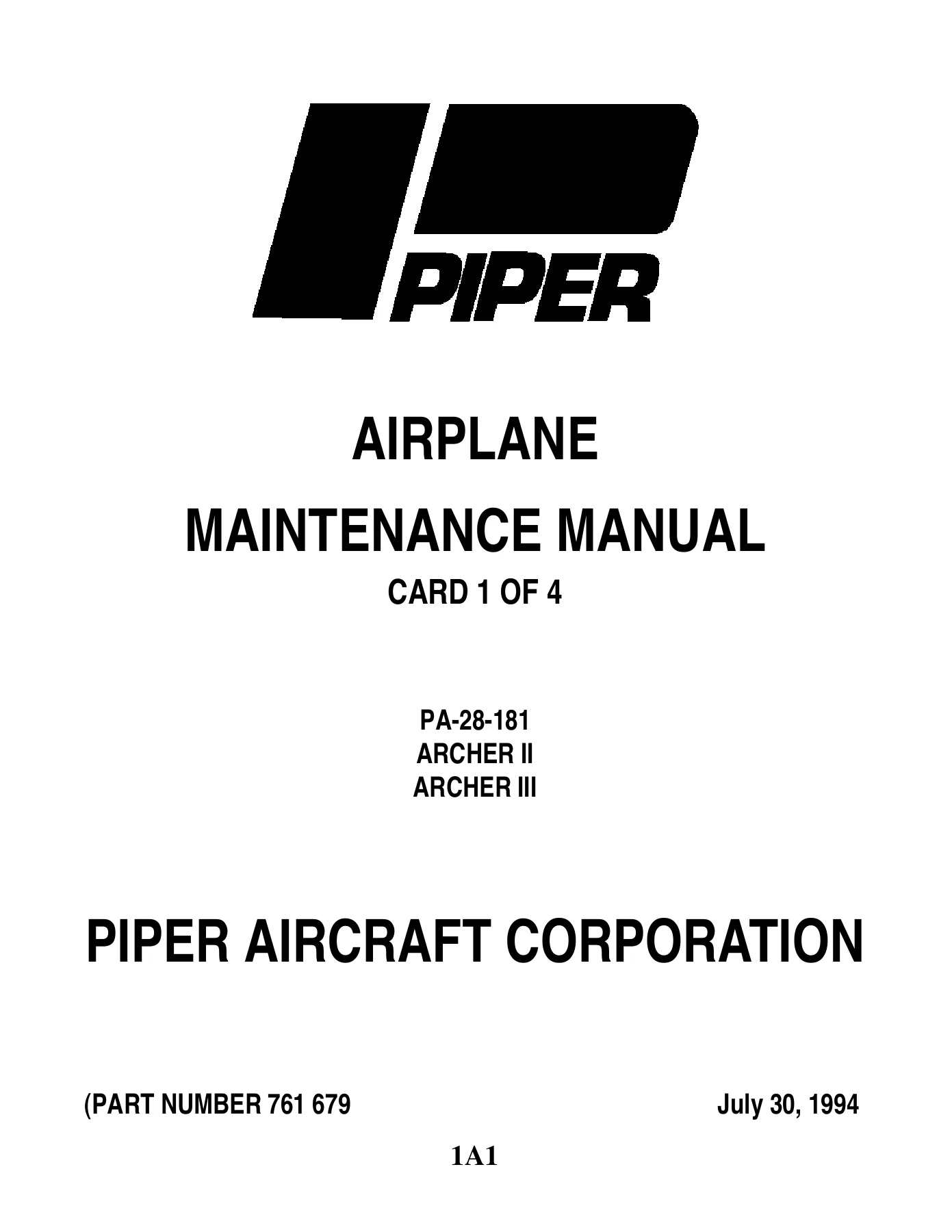
- Manual type: Airplane Maintenance Manual
- Brand / model: Piper PA-28-181 Archer II and Archer III
- Document number: Part Number 761 679
- Publication: Issued August 16, 1978; reissued July 30, 1994 (CR940731)
- Language: English
- Page count: 863
- File format: PDF
Which Airplanes This Manual Covers
The Piper PA-28-181 Archer II Archer III Airplane Maintenance Manual 761-679 1976 and Up is written for the PA-28-181 family as listed in the serial-number section of the introduction. Archer II production years and serial blocks printed in the book are:
- 1976: 28-7690001 to 28-7690479
- 1977: 28-7790001 to 28-7790607
- 1978: 28-7890001 to 28-7890564
- 1979: 28-7990001 to 28-7990626
- 1980: 28-8090001 to 28-8090382
- 1981: 28-8190001 to 28-8190336
- 1982: 28-8290001 to 28-8290188
- 1983: 28-8390001 to 28-8390090
- 1984: 28-8490001 to 28-8490112
- 1985: 28-8590001 to 28-8590092
- 1986: 28-8690001 to 28-8690056 and 2890001 to 2890205
Archer III coverage begins at serial 2890206 and up. Chart 601 identifies the engine as Avco-Lycoming O-360-A4M (Slick magnetos) or O-360-A4A (Bendix magnetos), rated 180 hp at 2700 propeller rpm, on 100 Low Lead aviation fuel, with an 8 U.S. quart oil sump. Electrical hardware splits by variant: Archer II uses a 12-volt Prestolite MZ4206 starter; Archer III uses a 24-volt Lycoming LW 15572 starter. Alternator applicability in the same chart includes Chrysler 3656624, Chrysler 4111810 (60 amp), Electro Systems ES4020 (60 amp), Prestolite ALY-6422 (60 amp), and Electrosystems ES 4032-99109-13 (70 amp) by serial effectivity.
Fixed-pitch Sensenich propellers called out are 76EM8S5-0-60 (28-7690001 through 28-7790607), 76EM8S5-0-62 (28-7890001 and up, and 2890001 through 2890205), and 76EM8S14-0-62 (2890206 and up), 76.0 in. diameter. Fuel is two 25-gallon wing tanks, 50 gallons total, 2 gallons unusable. Landing gear is fixed combination air-oil oleo gear with 6:00 x 6 wheels, nose tire 18 psi, main tires 24 psi.
Chapters Covered
- Chapter 4 Airworthiness Limitations — fatigue-life notes; propeller blade safe life listed as unlimited; airframe safe-life data stated as to be issued when available
- Chapter 5 Time Limits / Maintenance Checks — inspection requirements, preflight checks, over-limits inspection, 50/100/500/1000-hour periodic inspections, progressive inspection reference, unscheduled special inspections
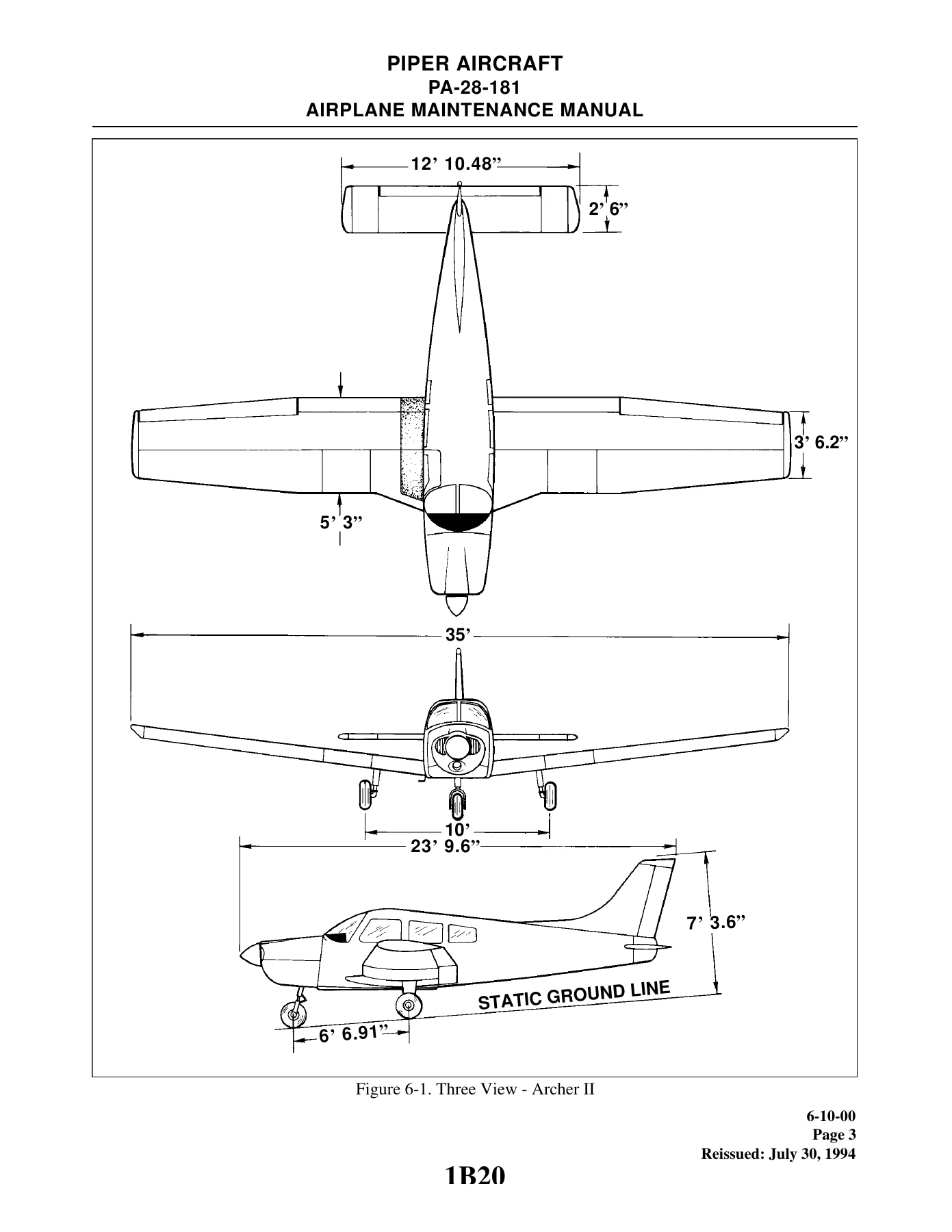
- Chapter 6 Dimensions and Areas — Chart 601 leading particulars, three-view drawings, station reference lines for Archer II and Archer III, access plates and panels
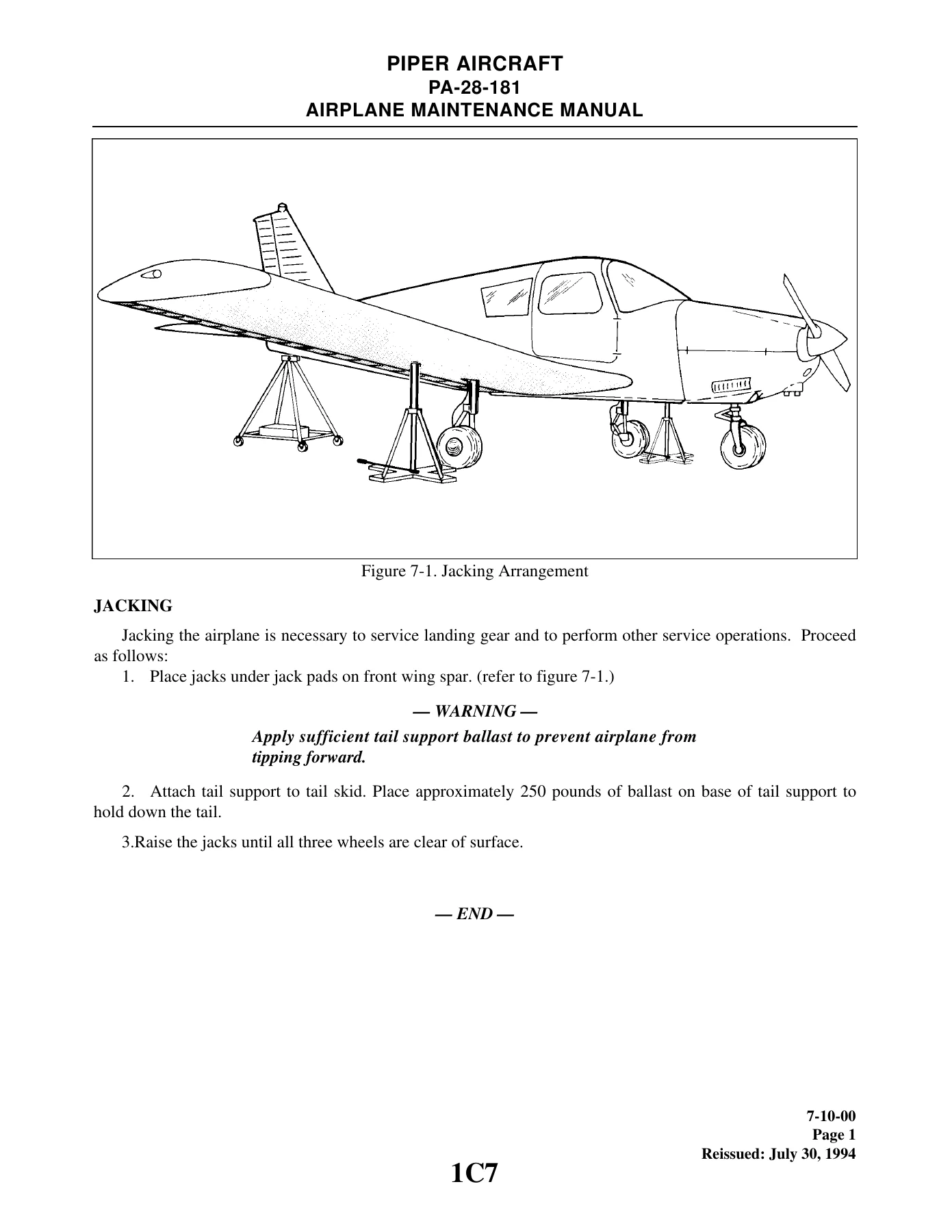
- Chapter 7 Lifting and Shoring — jacking arrangement and tail-support ballast
- Chapter 8 Leveling and Weighing — longitudinal and lateral leveling, weighing the airplane
- Chapter 9 Towing and Taxiing
- Chapter 10 Parking and Mooring
- Chapter 11 Placards and Markings — external and internal placards for Archer II and Archer III
- Chapter 12 Servicing — fuel filter bowl and screen, servicing points, oleo struts, tire balancer fixture, lubrication charts for landing gear, controls, cabin doors/seats, power plant, and air-conditioning condenser
- Chapter 20 Standard Practices — Airframe — torque wrench formula, rod-end bearings, Cherrylock rivet removal, hose and line markings, flareless fittings, corrosion types
- Chapter 21 Environmental System — cabin heat, defroster, fresh air, overhead vents, air-conditioning installation, service valves, charging equipment, compressor, belts, magnetic clutch, expansion valve, wiring schematics
- Chapter 22 Autoflight
- Chapter 23 Communications — ELT installations (Communications Components, Narco ELT 10, Narco ELT 910, Artex 110) with schematics and battery packs
- Chapter 24 Electrical Power — Prestolite, Chrysler, and Electrosystems alternators (exploded views, tests, brush and bearing work), Lamar regulator and overvoltage checks, battery hydrometer and charge tables for 12-volt Archer II and 24-volt Archer III, component load charts
- Chapter 25 Equipment / Furnishings — seat back lock, lumbar seat bladder
- Chapter 27 Flight Controls — cable inspection and wear, control column, aileron/rudder/stabilator/flap rigging tools and procedures, trim systems, cable tension versus temperature
- Chapter 28 Fuel — Archer II and Archer III fuel system diagrams, locking gas cap, filter bowl, plunger pump, quantity transmitter checks and tolerances
- Chapter 32 Landing Gear — main and nose oleo assemblies, wheel and brake assemblies, master cylinder and toe brakes, alignment tolerances
- Chapter 33 Lights — Archer II and Archer III annunciator panels, strobe connections, Archer III landing-light installation and adjustment
- Chapter 34 Navigation and Pitot/Static — pitot/static system and instrument troubleshooting charts
- Chapter 37 Vacuum System — auxiliary vacuum pump installations and electrical schematic
- Chapter 39 Electric / Electronic Panels and Multi-Purpose Parts
- Chapter 51 Structures — skin materials and thickness, baggage inspection-hole cutouts, thermoplastic repair of scratches, nicks, cracks, welds, and impact damage
- Chapter 52 Doors — door snubber, baggage-door lock tool
- Chapter 55 Stabilizers — empennage installation, control-surface balancing of stabilator and rudder
- Chapter 56 Windows — windshield and single-pane side window installation
- Chapter 57 Wings — stall strips, wing installation, aileron and flap installation, aileron balance
- Chapter 61 Propeller — nick removal, Archer II and Archer III propeller installation, torque limits
- Chapter 70 Standard Practices — Engine
- Chapter 71 Power Plant — static rpm charts, engine and cowling installation for Archer II and Archer III, ice detection system
- Chapter 73 Engine Fuel System — carburetor, primers, engine-control adjustment, fuel-pressure gauge
- Chapter 74 Ignition — magneto overhaul and timing (T-100 kit, 4200-series exploded view, Bendix inspection, impulse coupling), ignition-lead work, spark-plug removal, switch installations
- Chapter 77 Engine Indicating — EGT probe, tachometer troubleshooting
- Chapter 78 Exhaust — inspection points for Archer II and Archer III muffler and stacks
- Chapter 79 Oil System — oil pressure and temperature gauge troubleshooting
- Chapter 80 Starting — gear-reduction starting motor exploded view, commutator, armature and field tests, no-load and stall-torque hookups
- Chapter 91 Charts and Wiring Diagrams — flare and nut torques, conversions, hose specifications, consumable materials, vendor list, wire coding, electrical symbols, and the card-4 wiring diagrams (lighting, radio dimmer, and related circuits by serial effectivity)
Complete PDF Bookmark Tree
Complete Bookmarks
The complete bookmarks in the “Piper PA-28-181 Archer II Archer III Airplane Maintenance Manual 761-679 1976 and Up” are as follows:
+761-679 – PIPER AIRPLANE MAINTENANCE MANUAL – PA-28-181 ARCHER II, ARCHER IIIp. 1
+AEROFICHE CARD 1 OF 4p. 1
+INTRODUCTIONp. 3
Aerofiche Explanation And Revision Statusp. 3
Vendor Publicationsp. 4
Serial Number Informationp. 5
Gama System/Chapter Index Guidep. 6
List Of Illustrationsp. 8
List Of Chartsp. 15
+CHAPTER 4 – AIRWORTHINESS LIMITATIONSp. 17
Table Of Contents/Effectivityp. 18
+AIRWORTHINESS LIMITATIONSp. 19
+CHAPTER 5 – TIME LIMITS AND MAINTENANCE CHECKSp. 21
Table Of Contents/Effectivityp. 22
Generalp. 23
+TIME LIMITSp. 24
Inspection Requirementsp. 24
Preflight Checksp. 24
Over Limits Inspectionp. 24
+SCHEDULED MAINTENANCE CHECKSp. 25
Periodic Inspectionsp. 25
Progressive Inspectionp. 35
+UNSCHEDULED MAINTENANCE CHECKSp. 36
Special Inspections As Required, Upon Conditionp. 36
+CHAPTER 6 – DIMENSIONS AND AREASp. 39
Table Of Contents/Effectivityp. 40
Dimensionsp. 42
+STATION REFERENCE LINESp. 46
Archer IIp. 46
Archer IIIp. 48
Access And Inspection Provisionsp. 50
+CHAPTER 7 – LIFTING AND SHORINGp. 52
Table Of Contents/Effectivityp. 53
Jackingp. 55
+CHAPTER 8 – LEVELING AND WEIGHINGp. 57
Table Of Contents/Effectivityp. 58
Levelingp. 59
Weighingp. 60
+CHAPTER 9 – TOWING AND TAXIINGp. 62
Table Of Contents/Effectivityp. 63
Towingp. 64
Taxiingp. 65
+CHAPTER 10 – PARKING AND MOORINGp. 66
Table Of Contents/Effectivityp. 67
Parkingp. 68
Mooringp. 69
+CHAPTER 11 – REQUIRED PLACARDSp. 70
Table Of Contents/effectivityp. 71
Exterior Placards And Markingsp. 72
Interior Placards And Markingsp. 75
+REMOVAL AND INSTALLATION OF DECALSp. 79
Paper Decalsp. 79
Vinyl Film Decalsp. 79
+METAL DECALSp. 79
Cellophane Backedp. 79
Paper Backedp. 79
Metal Decals With No Adhesivep. 79
+MEYERCORD DECALSp. 79
Removal Of Meyercord Decalsp. 79
Installation Of Meyercord Decalsp. 80
+CHAPTER 12 – SERVICINGp. 81
Table Of Contents/Effectivityp. 82
Generalp. 83
+REPLENISHINGp. 85
+SERVICING FUEL SYSTEMp. 85
Filling Fuel Tanksp. 85
Anti-Icing Fuel Additivep. 85
Draining Moisture From Fuel Systemp. 86
Draining Fuel Systemp. 86
+SERVICING OIL SYSTEMp. 87
Draining Oil Sumpp. 87
Filling Oil Sumpp. 87
Oil Suction Screenp. 87
Oil Pressure Screenp. 88
Recommendations For Changing Oilp. 88
Oil Filter (Full Flow)p. 89
+SCHEDULED SERVICINGp. 91
Servicing Fuel Systemp. 92
+SERVICING LANDING GEARp. 92
+SERVICING OLEO STRUTSp. 92
Filling Nose Gear Oleo Strutp. 93
Filling Main Gear Oleo Strutp. 93
Inflating Oleo Strutsp. 95
+SERVICING BRAKE SYSTEMp. 96
Filling Brake Cylinder Reservoirp. 96
Draining Brake Systemp. 96
Servicing Tiresp. 96
Servicing Powerplantp. 97
+REMOVAL AND INSTALLATION OF INDUCTION AIR FILTERp. 97
Archer IIp. 97
Archer IIIp. 97
Cleaning And Inspection Of Air Filterp. 98
Servicing Propellerp. 98
Servicing Electrical Systemp. 98
+BATTERY SERVICINGp. 98
+BATTERY BOX CORROSION PREVENTIONp. 98
Archer IIp. 98
Archer III (S/N’s 2890206 And Up)p. 99
+LUBRICATION INSTRUCTIONSp. 99
Application Of Oilp. 100
Application Of Greasep. 100
Winterization Platep. 101
Lubrication Chartp. 101
+CHAPTER 20 – STANDARD PRACTICES/AIRFRAMEp. 115
Table Of Contents/Effectivityp. 116
Generalp. 117
+STANDARD PRACTICES – AIRFRAMEp. 118
Torque Wrenchesp. 118
Method For Installing Rod End Bearingsp. 119
Removal Of Cherrylock Rivetsp. 119
Identification Of Fluid Linesp. 120
Flareless Tube Assembliesp. 121
Support Clampsp. 123
Dye Penetrant Inspectionsp. 123
+AIRCRAFT FINISH CARE (CLEANING)p. 125
Exterior Surfacesp. 125
Windshield And Windowsp. 125
Headliner, Side Panels, And Seatsp. 126
Carpetsp. 126
Engine Compartmentp. 126
Fuel Systemp. 127
Landing Gearp. 127
+CORROSIONp. 128
Conditions Affecting Corrosionp. 128
Inspectionp. 128
Corrosion Removal And Controlp. 128
Areas Prone To Corrosionp. 130
+PAINTINGp. 132
Painting Safetyp. 132
Polyurethane Paint Safetyp. 132
Paint Applicationp. 133
Painting Sequencep. 134
Color Matchingp. 134
Trim And Registration Numbersp. 134
Paint System Compatibilityp. 135
Common Paint Troublesp. 135
Storagep. 136
Painting Facilityp. 136
Waxingp. 136
+CHAPTER 21 – ENVIROMENTAL SYSTEMp. 138
Table Of Contents/Effectivityp. 139
Generalp. 141
+HEATINGp. 142
Description And Operationp. 142
Heater Maintenancep. 142
+COOLINGp. 148
Description And Operationp. 148
Troubleshootingp. 148
+MALFUNCTION DETECTIONp. 156
Systems Using Refrigerant R12 (Archer II)p. 156
Systems Using Refrigerant HFC134a (Archer III)p. 156
+SPECIAL SERVICING PROCEDURESp. 158
Service Valvesp. 160
Charging Station And Hand Manifold Setp. 161
+EVACUATING THE SYSTEMp. 163
Using The Robinair 34700p. 164
Using A Hand Manifold Setp. 166
+LEAK DETECTIONp. 167
Using The Robinair 34700 Charging/Test Stationp. 167
Using A Manifold Hand Setp. 167
Discharging (Bleeding Or Purging) Systemp. 168
+CHARGING THE SYSTEMp. 169
Using Robinair 34700 Charging Standp. 169
+POST CHARGING OPERATIONAL CHECKp. 170
Using Robinair 34700 Charging Standp. 170
Using A Hand Manifold Setp. 171
+COMPONENT SERVICEp. 172
+COMPRESSOR SERVICEp. 172
Compressor Removalp. 172
Compressor Installationp. 173
Checking Compressor Oilp. 174
Replacement Of Compressor Drive Beltp. 175
Adjustment Of Drive Belt Tensionp. 178
+MAGNETIC CLUTCHp. 179
Magnetic Clutch Removalp. 179
Magnetic Clutch Installationp. 179
Refrigerant Lines And Routingp. 180
+RECEIVER-DEHYDRATORp. 180
Receiver-Dehydrator Removalp. 180
Receiver-Dehydrator Installationp. 180
+CONDENSERp. 181
Condenser Removalp. 181
Condenser Installationp. 181
Condenser Door Actuatorp. 181
Condenser Assembly Rigging Instructionsp. 181
+EXPANSION VALVEp. 183
Expansion Valve Removalp. 183
Expansion Valve Installationp. 184
+EVAPORATORp. 184
Evaporator Removalp. 184
Evaporator Installationp. 184
Pressure Relief Switchp. 186
+ELECTRICAL INSTALLATIONp. 186
Adjustment Of Throttle Switchp. 186
Fuse Replacementp. 186
+CABIN VENT SYSTEMp. 190
Overhead Vent System. (Not Available With Air Conditioning)p. 190
+OVERHEAD VENT BLOWERp. 190
Overhead Vent Blower Descriptionp. 190
Removal Of Blower Assemblyp. 190
Disassembly Of Blower Assemblyp. 190
Reassembly Of Blower Assemblyp. 190
Installation Of Blower Assemblyp. 191
+CHAPTER 22 – AUTO FLIGHTp. 194
Table Of Contents/Effectivityp. 195
Generalp. 196
+AUTOPILOTp. 197
Non-Piper AFCS Equipment Manufacturersp. 197
Piper AFCS Equipmentp. 197
+CHAPTER 23 – COMMUNICATIONSp. 199
Table Of Contents/Effectivityp. 200
Generalp. 201
+EMERGENCY LOCATOR TRANSMITTERp. 202
Descriptionp. 202
Garrett ELT Battery Removal And Installationp. 202
Communications Components Corp. ELT Battery Removal And Installationp. 203
Narco 10 ELT Batttery Removal And Installation (S/N’s 28-7990457 Thru 28-8690056 And 2879001 Thru 2890139)p. 204
Testing Emergency Locator Transmitter (ELT 10)p. 207
Description, Operation, And Testing Of Pilot’s Remote Switch (ELT 10 And ELT 910)p. 207
Narco 910 ELT Batttery Removal And Installation (S/N’s 2890140 Thru 2890205)p. 208
Testing ELT 910 Emergency Locator Transmitterp. 208
+ARTEX 110 E. L. Tp. 209
General Informationp. 209
Artex 110 ELT Battery Removal And Installation (Archer III, S/N’s 2890206 And Up)p. 210
Testing The Artex ELT 110 Emergency Locator Transmitterp. 211
+AVIONICS MASTER AND EMERGENCY SWITCH CIRCUITp. 213
+DESCRIPTION AND OPERATIONp. 213
Archer II (S/N’s 28-7690001 Thru 28-8690056 And 2890001 Thru 2890205)p. 213
Archer III (S/N’s 2890206 And Up)_p. 213
+CHAPTER 24 – ELECTRICAL POWERp. 214
Table Of Contents/Effectivityp. 215
+GENERALp. 218
+DESCRIPTION AND OPERATIONp. 218
Archer II (S/N's 28-7690001 Thru 28-8190264)p. 218
Archer II (S/N’s 28-8190265 Thru 28-8690056 And 2890001 Thru 2890205)p. 218
Archer III (S/N’s 2890206 And Up)p. 218
Troubleshootingp. 219
+DC GENERATIONp. 225
+PRECAUTIONSp. 225
+PRESTOLITE 14 VDC, 60 AMP ALTERNATOR SYSTEM (ARCHER II)p. 226
Description Of Prestolite Alternatorp. 226
Checking Prestolite Alternator Systemp. 228
Prestolite Alternator Service Proceduresp. 229
Overhaul Of Prestolite Alternatorp. 229
Disassembly Of Prestolite Alternatorp. 230
Inspecting And Testing Components Of Prestolite Alternatorp. 230
Assembly Of Prestolite Alternatorp. 232
Testing Prestolite Alternatorp. 234
Prestolite Alternator Service Tipsp. 234
Prestolite Alternator Service Test Specificationsp. 236
+CHRYSLER 14 VDC, 60 AMP ALTERNATOR SYSTEM (ARCHER IIp. 237
Description Of Chrysler Alternator Systemp. 237
Checking Chrysler Alternator Systemp. 239
Overhaul Of Chrysler Alternatorp. 239
Chrysler Alternator Rotor Field Coil Current Drawp. 240
Testing Chrysler Alternator Internal Field Circuitp. 240
Inspection Of Chrysler Alternatorp. 241
+TESTING RECTIFIER ASSEMBLIES OF CHRYSLER ALTERNATORp. 242
Testing Of Positive Rectifiers Using C-3829 Testerp. 242
Testing Of Negative Rectifiers Using C-3829 Testerp. 243
Testing Of Rectifier Assemblies Using Test Lampp. 243
Removal Of Chrysler Alternator Rectifier And Heatsink Assemblyp. 244
Testing Of Chrysler Alternator Statorp. 245
Removal Of Chrysler Alternator Pulley And Bearingp. 245
Testing Of Chrysler Alternator Rotorp. 247
Chrysler Alternator Slip Ringsp. 247
Assembly Of Chrysler Alternatorp. 247
+ELECTROSYSTEMS 28 VDC, 70 AMP ALTERNATOR (ARCHER IIIp. 252
Description Of Electrosystems Alternatorp. 252
Checking Electrosystems Alternator Systemp. 253
Electrosystems Alternator Service Proceduresp. 255
Overhaul Of Electrosystems Alternatorp. 255
Disassembly Of Electrosystems Alternatorp. 256
Inspecting And Testing Components Of Electrosystems Alternatorp. 257
Assembly Of Electrosystems Alternatorp. 259
Testing Electrosystems Alternatorp. 261
Prestolite Electrosystems Service Tipsp. 261
Prestolite Alternator Service Test Specificationsp. 262
Checking Alternator Belt Tensionp. 263
+BATTERYp. 264
+ARCHER IIp. 264
Servicing Batteryp. 264
Removal Of Batteryp. 264
Installation Of Batteryp. 264
Testing Batteryp. 265
Charging Batteryp. 265
Battery Box Corrosion Preventionp. 265
+ARCHER III (S/N’S 2890206 AND UP)p. 266
Battery Removalp. 266
Removing Acid Recovery (Vent) Jarp. 266
Cleaning Batteryp. 267
Cleaning Acid Recovery Jar And Vent Linesp. 267
Battery Installationp. 267
Installing Acid Recovery (Vent) Jarp. 268
Battery Charging – (Gill Model G-243)p. 268
Hydrometer Reading And Battery Chargep. 269
Battery Dischargep. 270
Battery Temperature Considerationsp. 271
Battery Repairs, Storage, And Service Tipsp. 271
Preparing New Dry Charged Battery For Installationp. 272
+CHECKING VOLTAGE REGULATORp. 272
To Test The 14 Volt Regulatorp. 272
14 VDC System Regulator Overvoltage Checkp. 274
Checking Overvoltage Relay (14 VDC System Only)p. 274
To Test The 28 Volt Regulatorp. 275
28 VDC System Regulator Overvoltage Checkp. 275
+EXTERNAL POWERp. 278
External Power Receptacle Operationp. 278
+ELECTRICAL SYSTEM LOAD DISTRIBUTIONp. 280
Archer IIp. 280
Archer III (S/N’s 2890206 And Up)p. 281
+AEROFICHE CARD 2 OF 4p. 283
+INTRODUCTIONp. 285
Aerofiche Explanation And Revision Statusp. 285
Vendor Publicationsp. 286
Serial Number Informationp. 287
Gama System/Chapter Index Guidep. 288
List Of Illustrationsp. 290
List Of Chartsp. 297
List Of Illustrationsp. 298
+CHAPTER 25 – EQUIPMENT/FURNISHINGp. 299
Table Of Contents/Effectivityp. 300
+FLIGHT COMPARTMENTp. 301
Rigging Instructions – Seat Back Lock And Releasep. 301
+LUMBAR SEATSp. 301
Descriptionp. 301
Removal Of Lumbar Bladderp. 301
Installation Of Lumbar Bladderp. 302
Shoulder Harness Inertia Reel Adjustmentp. 304
+CHAPTER 27 – FLIGHT CONTROLSp. 306
Table Of Contents/Effectivityp. 307
+GENERALp. 309
Description And Operationp. 309
Standard Proceduresp. 309
+CONTROL CABLE INSPECTIONp. 310
Cable Damagep. 310
External Wear Patternsp. 312
Internal Cable Wearp. 312
Corrosionp. 313
Cable Maintenancep. 314
Cable Fittingsp. 314
Pulleysp. 314
+AILERON CONTROLSp. 317
Troubleshootingp. 317
+CONTROL COLUMNp. 318
Removal Of Control Column Assemblyp. 318
Installation Of Control Column Assemblyp. 320
+AILERON CONTROL CABLESp. 322
Removal Of Aileron Control Cablesp. 322
Installation Of Aileron Control Cablesp. 324
+AILERON BELLCRANK ASSEMBLYp. 324
Removal Of Aileron Bellcrank Assemblyp. 324
Installation Of Aileron Bellcrank Assemblyp. 325
Rigging And Adjustment Of Aileron Controlsp. 325
+RUDDER CONTROLSp. 331
Troubleshootingp. 331
+RUDDER AND STEERING PEDAL ASSEMBLYp. 332
Removal Of Rudder And Steering Pedal Assemblyp. 332
Installation Of Rudder And Steering Pedal Assemblyp. 334
+RUDDER CONTROL CABLESp. 334
Removal Of Rudder Control Cablesp. 334
Installation Of Rudder Control Cablesp. 336
Rigging And Adjustment Of Rudder Controlsp. 336
+RUDDER TRIM CONTROLSp. 339
Removal Of Rudder Trim Controlsp. 339
Installation Of Rudder Trim Controlsp. 339
Rigging And Adjustment Of Rudder Trim Controlsp. 340
+STABILATOR AND TABp. 342
Troubleshootingp. 342
+STABILATOR CONTROL CABLESp. 343
Removal Of Stabilator Control Cablesp. 343
Installation Of Stabilator Control Cablesp. 344
Rigging And Adjustment Of Stabilator Controlsp. 346
+STABILATOR TRIM CONTROLSp. 348
+STABILATOR TRIM ASSEMBLYp. 348
Removal Of Forward Stabilator Trim Assemblyp. 348
Installation Of Forward Stabilator Trim Assemblyp. 350
Removal Of Aft Stabilator Trim Assemblyp. 351
Installation Of Aft Stabilator Trim Assemblyp. 351
Rigging And Adjustment Of Stabilator Trimp. 352
+STALL WARNINGp. 352
Removal Of Lift Detectorp. 353
Installation Of Lift Detectorp. 353
Adjustment Of Lift Detectorp. 353
+FLAP CONTROLSp. 355
Troubleshootingp. 355
+WING FLAPS CONTROLSp. 355
Removal Of Wing Flap Controlsp. 355
Installation Of Wing Flap Controlsp. 357
Rigging And Adjustment Of Wing Flapsp. 359
+CHAPTER 28 – FUELp. 362
Table Of Contents/Effectivityp. 363
+FUEL SYSTEMp. 365
Generalp. 365
+DESCRIPTIONp. 365
Archer IIp. 365
Archer IIIp. 365
Troubleshootingp. 367
+STORAGEp. 371
+FUEL TANKp. 371
Removal Of Fuel Tankp. 371
Inspection And Repair Of Fuel Tankp. 371
Installation Of Fuel Tankp. 371
+LOCKING FUEL CAPp. 371
+ARCHER IIp. 371
Disassembly Of Locking Fuel Capp. 371
Assembly Of Locking Fuel Capp. 371
+ARCHER III FLUSH TYPE CAPp. 371
Disassembly Of Locking Fuel Capp. 371
Assembly Of Locking Fuel Capp. 372
+DISTRIBUTIONp. 374
Generalp. 374
+FUEL SELECTOR VALVEp. 374
Removal Of Fuel Selector Valvep. 374
Installation Of Fuel Selector Valvep. 374
+FUEL FILTER BOWL AND SCREENp. 374
Removal Of Fuel Filter Bowl And Housingp. 374
Cleaning And Inspection Of Filter Bowl Screenp. 374
Installation Of Fuel Filter Bowl And Screenp. 375
+ELECTRIC FUEL PUMPp. 375
Generalp. 375
Removal Of Electric Fuel Pumpp. 375
Disassembly Of Electricfuel Pumpp. 376
Cleaning, Inspection, And Repair Of Electric Fuel Pumpp. 377
Resistance Check (Plunger Type Pump)p. 377
Assembly Of Electric Fuel Pumpp. 377
Adjustment Of Electric Fuel Pump (Bench Test)p. 377
Adjustment Of Electric Fuel Pump (In Airplane)p. 378
Installation Of Electric Fuel Pumpp. 378
+LINES AND FITTINGSp. 378
Inspection And Tightening Of Fuel Line Union Fittingsp. 378
Replacement Of Fittingsp. 379
+INDICATINGp. 382
+FUEL QUANTITY TRANSMITTER UNITp. 382
Removal Of Archer II And Archer III Fuel Quantity Transmitter Unitp. 382
Installation Of Archer II And Archer III Fuel Quantity Transmitter Unitp. 382
+FUEL QUANTITY TRANSMITTER/GAUGE CHECK (INSTALLEDp. 382
Archer II With A. C. Sparkplug Gaugesp. 382
Archer II With Stewart Warner Or Rochester Gaugesp. 383
Archer III 28 VDC Fuel Gaugesp. 384
+CHECK AND ADJUSTMENT OF FUEL QUANTITY TRANSMITTER UNITp. 387
Archer II 14 VDC Fuel Quantity Transmitter Check. (Piper P/N 486 520)p. 387
Archer III 28 VDC Fuel Quantity Transmitter Check. (Piper P/N 548 671)p. 387
Fuel Quantity Indicatorp. 390
+CHAPTER 32 – LANDING GEARp. 392
Table Of Contents/Effectivityp. 393
+GENERALp. 396
Descriptionp. 396
Troubleshootingp. 396
+MAIN GEARp. 400
Disassembly Of Main Gear Oleop. 400
Cleaning, Inspection And Repair Of Main Gear Oleop. 400
Assembly Of Main Gear Oleop. 403
Removal Of Main Landlng Gearp. 403
Cleaning, Inspection And Repair Of Main Landing Gearp. 405
Installation Of Main Landing Gearp. 405
+NOSE GEARp. 407
Disassembly Of Nose Gear Oleop. 407
Cleaning, Inspection, And Repair Of Nose Gear Oleop. 409
Nose Gear Oil Orifice Retainer Ring Installationp. 409
Assembly Of Nose Gear Oleop. 409
Removal Of Nose Landing Gearp. 412
Cleaning, Inspection, And Repair Of Nose Landing Gearp. 412
Installation Of Nose Landing Gearp. 412
Alignment Of Nose Gearp. 413
+WHEELS AND BRAKESp. 416
Removal And Disassembly Of Main Wheelp. 416
Inspection Of Main Wheel Assemblyp. 417
Assembly And Installation Of Main Wheelp. 417
Removal And Disassembly Of Nose Wheelp. 417
Inspection Of Nose Wheel Assemblyp. 418
Assembly And Installation Of Nose Wheelp. 418
Brake Adjustment And Lining Tolerancep. 419
Removal And Disassembly Of Brake Assemblyp. 419
Cleaning, Inspection, And Repair Of Brake Assemblyp. 421
Assembly And Installation Of Brake Assemblyp. 421
Removal Of Brake Master Cylinder (Hand Brake)p. 421
Disassembly Of Brake Master Cylinderp. 421
Cleaning, Inspection, And Repair Of Brake Master Cylinderp. 423
Assembly Of Brake Master Cylinderp. 423
Installation Of Brake Master Cylinder (Hand Brake)p. 424
Removal Of Brake Cylinder (Toe Brake)p. 424
Disassembly Of Brake Cylinderp. 424
Cleaning, Inspection, And Repair Of Brake Cylinderp. 424
Assembly Of Brake Cylinderp. 427
Installation Of Brake Cylinderp. 427
Brake Bleeding Procedure (Gravity)p. 427
Brake Bleeding Procedure (Pressure)p. 428
Brake System Leak Checkp. 428
Bleeding Of The Brakes After A Unit Has Been Changedp. 429
+CHAPTER 33 – LIGHTSp. 431
Table Of Contents/Effectivityp. 432
+GENERALp. 434
+DESCRIPTION AND OPERATIONp. 434
Archer IIp. 434
Archer III (S/N’s 2890206 And Up)p. 434
+FLIGHT COMPARTMENTp. 436
+INSTRUMENT PANEL LIGHTSp. 436
Archer IIp. 436
Archer III (S/N’s 2890206 And Up)p. 436
+REMOVAL OF LIGHT CONTROLSp. 436
Removal Of Archer II Dimmer Control Assemblyp. 436
+REMOVAL OF ARCHER III POWER SUPPLY OR POTENTIOMETER CONTROL (S/NS 2890206 AND UPp. 436
To Remove Dimmer Controlp. 436
To Remove Dimmer Control Potentiometerp. 436
+INSTALLATION OF LIGHT CONTROLSp. 437
Installation Of Archer II Dimmer Control Assemblyp. 437
+INSTALLATION OF ARCHER III DIMMER CONTROL OR POTENTIOMETER CONTROL (S/NS 2890206 AND UPp. 437
To Install Dimmer Controlp. 437
To Install Control Potentiometerp. 437
+ANNUNCIATOR PANELp. 437
Archer II Description And Operationp. 437
Archer III Description And Operation (S/N’s 2890206 And Up)p. 438
Troubleshooting Archer II Annunciator Panelp. 439
Troubleshooting Archer III Annunciator Panelp. 440
Replacement Of Archer II Annunciator Panel Light Bulbsp. 444
Replacement Of Archer III Annunciator Panel Light Bulbs (S/N’s 2890206 And Up)p. 444
Removal And Installation Of Archer II And Archer III Vacuum Sensor Switchp. 445
Removal And Installation Of Archer II And Archer III Oil Pressure Sensor Switch R4p. 445
+EXTERIORp. 448
+ARCHER II – 14 VDC SYSTEMp. 448
Descriptionp. 448
Removal And Installation Of Landing Lightp. 448
+ANTI-COLLISION BEACON LIGHTp. 448
Removalp. 448
Installationp. 448
+ANTI-COLLISION STROBE LIGHTp. 448
Descriptionp. 448
Removal Of Wing Tip Strobe Lightp. 448
Installation Of Wing Tip Strobe Lightp. 449
+FIN TIP STROBE LIGHTp. 449
Removal Of Fin Tip Strobe Lightp. 449
Installation Of Fin Tip Strobe Lightp. 449
+STROBE POWER SUPPLYp. 449
Removal Of Strobe Power Supplyp. 449
Installation Of Strobe Power Supplyp. 450
Troubleshooting Strobe Lightsp. 451
+ARCHER III – 28 VDC SYSTEMp. 452
Descriptionp. 452
Removal And Installation Of Landing Light(s)p. 452
Adjustment (Alignment) Of Landing Lightp. 453
+NAVIGATION (POSITION) LIGHTSp. 455
Descriptionp. 455
Removing Bulb(s)p. 455
Installing Bulb(s)p. 455
+STROBE ANTI-COLLISION LIGHTp. 455
Descriptionp. 455
Removal Of Wing Tip Strobe Lightp. 455
Installation Of Wing Tip Strobe Lightp. 456
+STROBE POWER SUPPLYp. 456
Removal Of Power Supplyp. 456
Installation Of Strobe Power Supplyp. 456
Troubleshooting Strobe Lightsp. 456
+CHAPTER 34 – NAVIGATION AND PILOT/STATICp. 460
Table Of Contents/Effectivityp. 461
+NAVIGATION AND PILOT STATICp. 463
+GENERALp. 463
Description And Operationp. 463
Removal And Replacement Of Face Mounted Instrumentsp. 463
Gyro Fitting Installation Procedurep. 464
+FLIGHT ENVIRONMENTAL DATA / PITOT STATICp. 467
Description And Operationp. 467
Vertical Speed Indicatorp. 467
Sensitive Altimeterp. 468
Airspeed Indicatorp. 469
+OUTSIDE AIR TEMPERATURE GAUGE (OAT)p. 470
+REMOVING AND INSTALLING OUTSIDE TEMPERATURE GAUGEp. 470
Archer II Windshield Mounted Instrumentp. 470
Archer III Side Panel Mounted Instrumentp. 471
+ATTITUDE AND DIRECTIONp. 473
+GYRO INSTRUMENTSp. 473
Generalp. 473
Maintenance Of Gyro Instruments – Generalp. 473
Gyro Fitting Installation Procedure (Sigma Tek, formally Edo-Aire)p. 473
+AIR DRIVEN ATTITUDE DEVATION INDICATORS (ADI)p. 473
+ELECTRICALLY DRIVEN ATTITUDE DEVIATION INDICATORSp. 475
Generalp. 475
Operational Limitationsp. 475
Troubleshootingp. 476
+HEADING INDICATORS (DIRECTIONAL GYROS)p. 476
Air Drive Heading Indicatorsp. 476
Electrically Driven Heading Indicator (Directional Gyro)p. 476
+TROUBLESHOOTINGp. 477
Generalp. 477
Air Driven Gyrosp. 477
+MAGNETIC COMPASSp. 478
Generalp. 478
Troubleshootingp. 478
Adjustment Of Magnetic Compassp. 479
+TURN INDICATORp. 480
Generalp. 480
Troubleshotingp. 480
+CHAPTER 37 – VACUUMp. 482
Table Of Contents/Effectivityp. 483
+GENERALp. 485
Description And Operationp. 485
Troubleshootingp. 485
+DISTRIBUTIONp. 489
+VACUUM SYSTEM SERVICE TIPSp. 489
Hoses And Clampsp. 489
Vacuum Gaugesp. 489
Gyro Filtersp. 490
Vacuum Regulatorp. 490
+ENGINE DRIVEN VACUUM PUMPp. 490
Removal Of Engine Driven Vacuum Pumpp. 491
Installation Of Engine Driven Vacuum Pumpp. 491
+AUXILIARY VACUUM PUMP. (ARCHER II AND ARCHER III)p. 491
Auxiliary Vacuum Pump, Engine Off Operational Checkp. 492
Removal Of Auxiliary Vacuum Pumpp. 492
Installation Of Auxiliary Vacuum Pumpp. 493
Replacing Pump Fittingsp. 497
+VACUUM REGULATOR VALVEp. 497
Adjustment Of Vacuum Regulator Valvep. 497
Removal And Replacement Of Regulator Valvep. 498
+INDICATINGp. 500
+VACUUM GAUGEp. 500
Removal Of Vacuum Gaugep. 500
Installation Of Vacuum Gaugep. 500
+VACUUM SENSORp. 500
Removal Of Vacuum Sensorp. 500
Installation Of Vacuum Sensorp. 500
+CHAPTER 39 – ELECTRIC/ELECTRONIC PANELS AND MULTI-PURPOSE PARTp. 502
Table Of Contents/Effectivityp. 503
+INSTRUMENT AND CONTROL PANELSp. 505
+REMOVAL AND REPLACEMENT OF FACE MOUNTED INSTRUMENTSp. 505
Archer IIp. 505
Archer IIIp. 505
Removal And Replacement Of Cluster Mounted Instrumentsp. 505
+MULTIPURPOSE ELECTRICAL AND ELECTRONIC PARTSp. 508
+ELECTRICAL SWITCHESp. 508
+ARCHER IIp. 508
Removal Of Electrical Switchesp. 508
Installation Of Electrical Switchesp. 508
+ARCHER III (S/N’S 2890206 AND UP)p. 508
To Remove Overhead Panel Switch(es)p. 508
To Install Overhead Panel Switch(es)p. 509
To Remove Avionics Or Pitot Heat Switch(es)p. 509
To Install Avionics Or Pitot Heat Switch(es)p. 509
+CIRCUIT BREAKERSp. 509
Removal Of Circuit Breakersp. 509
Installation Of Circuit Breakersp. 510
+CHAPTER 51 – STRUCTURESp. 512
Table Of Contents/Effectivityp. 513
+GENERALp. 515
+STRUCTURAL REPAIRSp. 517
+BAGGAGE COMPARTMENT INSPECTION HOLE AND COVER PLATEp. 517
Generalp. 517
Baggage Compartment Inspection Holes Fabrication Procedurep. 517
+FIBERGLASS REPAIRSp. 518
Minor Scratch And Crack Repairp. 518
Hole Repairp. 522
Fiberglass Fracture And Patch Repairsp. 522
Adding Layers To Undamaged Areasp. 523
+GENERAL THERMOPLASTIC REPAIRSp. 524
Surface Preparationp. 524
Surface Scratches, Abrasions Or Ground-in-dirtp. 525
Deep Scratches, Shallow Nicks, And Small Holes: (Less Than 1 Inch In Diameter)p. 525
Cracksp. 527
Repairing Major Damage: (Larger Than 1 Inch In Diameter)p. 527
Stress Linesp. 527
Painting The Repairp. 531
A.B.S. Thermoplastic Landing Gear Wheel And Strut Fairing Repair Instructionsp. 531
+SAFETY WALK REPAIRp. 531
Surface Preparationp. 531
Product Listing For Liquid Safety Walk Compoundp. 531
Application Of Liquid Safety Walk Compoundp. 532
Surface Preparation For Pressure Sensitive Safety Walkp. 532
Application Of Pressure Sensitive Safety Walkp. 532
+CHAPTER 52 – DOORSp. 534
Table Of Contents/Effectivityp. 535
Generalp. 537
+PASSENGER/CREWp. 539
+CABIN DOORp. 539
Removal Of Doorp. 539
Installation Of Doorp. 539
Adjustment Of Doorp. 539
+DOOR LATCH MECHANISMp. 539
Removal Of Door Latch Mechanismp. 539
Installation Of Door Latch Mechanismp. 539
Adjustment Of Door Latch Mechanismp. 539
+DOOR LOCK ASSEMBLYp. 539
Removal Of Door Lock Assemblyp. 539
Installation Of Door Lock Assemblyp. 540
+DOOR SAFETY LATCHp. 540
Removal Of Door Safety Latchp. 540
Installation Of Door Safety Latchp. 540
Adjustment Of Door Safety Latchp. 540
Removal And Installation Of Door Snubberp. 540
+CARGOp. 544
+BAGGAGE DOORp. 544
Removal Of Baggage Doorp. 544
Installation Of Baggage Doorp. 544
+BAGGAGE DOOR LOCK ASSEMBLYp. 544
Removal Of Baggage Door Lock Assemblyp. 544
Installation Of Baggage Door Lock Assemblyp. 544
+BAGGAGE DOOR HINGEp. 544
Removal Of Baggage Door Hingep. 544
Installation Of Baggage Door Hingep. 544
+CHAPTER 55 – STABILIZERSp. 547
Table Of Contents/Effectivityp. 548
Generalp. 549
+STABILIZER AND TABp. 550
Removal Of Stabilatorp. 550
Installation Of Stabilatorp. 550
+STABILATOR TRIM TABp. 551
Removal Of Stabilator Trim Tabp. 551
Installation Of Stabilator Trim Tabp. 551
Checking Stabilator Surfaces Free Playp. 551
+BALANCINGp. 555
Balancing Equipmentp. 555
Balancing Stabilatorp. 555
+VERTICAL STABILIZERp. 557
Removal Of Vertical Finp. 557
Installation Of Vertical Flnp. 557
+RUDDER AND TABp. 559
Removal Of Rudderp. 559
Installation Of Rudderp. 559
Balancing Rudderp. 559
+AEROFICHE CARD 3 OF 4p. 562
+INTRODUCTIONp. 564
Aerofiche Explanation And Revision Statusp. 564
Vendor Publicationsp. 565
Serial Number Informationp. 566
Gama System/Chapter Index Guidep. 567
List Of Illustrationsp. 569
List Of Chartsp. 576
List Of Illustrationsp. 577
+CHAPTER 56 – WINDOWSp. 578
Table Of Contents/Effectivityp. 579
Generalp. 581
+FLIGHT COMPARTMENTp. 582
Removal Of Windshieldp. 582
Installation Of Windshieldp. 582
+CABINp. 585
Removal Of Side Windowsp. 585
Installation Of Side Windowsp. 585
+CHAPTER 57 – WINGSp. 588
Table Of Contents/Effectivityp. 589
+GENERALp. 591
+AUXILIARY STRUCTUREp. 592
Removal Of Wing Tipp. 592
Repair Of Wing Tipp. 592
Installation Of Wing Tipp. 592
Installation Of Stall Stripp. 592
+ATTACH FITTINGSp. 595
Removal Of Wingp. 595
Installation Of Wingp. 595
+FLIGHT SURFACESp. 603
Removal Of Aileronp. 603
Installation Of Aileronp. 603
Checking Aileron Free Playp. 603
Balancing Aileronp. 603
+WING FLAPp. 603
Removal Of Wing Flapp. 603
Installation Of Wing Flapp. 604
+CHAPTER 61 – PROPELLARp. 609
Table Of Contents/Effectivityp. 610
Generalp. 612
+PROPELLER ASSEMBLYp. 613
+REMOVAL OF PROPELLERp. 613
Archer IIp. 613
Archer III (S/N’s 2890206 And Up)p. 613
Cleaning, Inspection And Repair Of Propellerp. 613
+INSTALLATION OF PROPELLERp. 614
Archer IIp. 614
Archer III (S/N’s 2890206 And Up)p. 615
Blade Trackp. 616
+CHAPTER 70 – STANDARD PRACTICES – ENGINEp. 619
Table Of Contents/Effectivityp. 620
Standard Practices – Enginep. 622
+CHAPTER 71 – POWER PLANTp. 624
Table Of Contents/Effectivityp. 625
+POWER PLANTp. 627
Generalp. 627
Description And Operationp. 627
Troubleshooting (Fault Isolation)p. 628
+STATIC RPM DETERMINATIONp. 633
Static RPM Test Procedurep. 633
Scopep. 633
Equipmentp. 633
Test Procedurep. 634
Siimplified Test Procedurep. 634
Expanded Test Procedurep. 634
Test Resultsp. 635
Removal Of Enginep. 640
Installation Of Enginep. 641
+COWLINGp. 647
+MAINTENANCE OF COWLINGp. 647
+REMOVAL OF COWLINGp. 647
Archer IIp. 647
Archer III – S/N’s 2890206 And Upp. 647
Cleaning, Inspection And Repair Of Cowlingp. 649
+INSTALLATION OF COWLINGp. 649
Archer IIp. 649
Archer III – S/N’s 2890206 And Upp. 649
+AIR INTAKESp. 653
+CARBURETOR ICE DETECTOR – ARCHER IIp. 653
Generalp. 653
Troubleshootingp. 653
Functional Check Of Ice Detector Probep. 653
Removal Of Ice Detector Probep. 654
Installation Of Ice Detector Probep. 654
+CHAPTER 73 – ENGINE FUEL SYSTEMp. 657
Table Of Contents/Effectivityp. 658
Generalp. 660
+DISTRIBUTIONp. 661
Carburetor Maintenancep. 661
Throttle Armp. 661
Adjustment Of Idle Mixturep. 661
Adjustment Of Idle Speedp. 662
+PRIMER SYSTEMSp. 662
+ARCHER IIp. 662
Removal Of Engine Primerp. 662
Disassembly, Cleaning And Assembly Of Engine Primerp. 662
Installation Of Engine Primerp. 663
Archer III (S/N’s2890206 And Up)p. 663
Primer Jetsp. 663
+CONTROLLINGp. 667
Adjustment Of Throttle And Mixture Controlsp. 667
+INDICATINGp. 669
Fuel Pressure Gaugep. 669
+CHAPTER 74 – IGNITIONp. 673
Table Of Contents/Effectivityp. 674
+GENERALp. 676
Description And Operationp. 676
Troubleshootingp. 676
+ELECTRICAL POWER SUPPLYp. 679
+ARCHER IIp. 679
Slick Magnetosp. 679
Removal Of Magnetosp. 679
Inspection Of 4000 And 4200 Series Magnetosp. 679
Installation And Procedure For Timing 4000/4100 Series Magneto To Enginep. 681
+OVERHAUL INSTRUCTIONS FOR 4200 SERIES MAGNETOSp. 682
Disassembly Of Magnetosp. 682
Cleaning And Inspection Of Magnetosp. 685
Assembly Of Magnetosp. 685
4200 Series Magnetos Internal Timing Procedurep. 689
4200 Series Magnetos Installation And Timing Magneto To Engine Procedurep. 689
+BENDIX MAGNETOp. 690
Inspection Of Magnetosp. 690
Removal Of Magnetop. 692
20 And -200 Series Magnetos Internal Timing Procedurep. 692
Installation And Timing Magneto To Engine Procedurep. 694
Archer IIIp. 695
+DISTRIBUTIONp. 698
+HARNESSp. 698
Inspection Of Harnessp. 698
Removal Of Harnessp. 698
Disassembly Of Harnessp. 698
Harness Assembly Instructionsp. 701
Installation Of Harnessp. 703
+SPARK PLUGSp. 703
Removal Of Spark Plugsp. 703
Inspection And Cleaning Of Spark Plugsp. 704
Installation Of Spark Plugsp. 704
+SWITCHINGp. 707
+IGNITION AND STARTER SWITCH(ES)p. 707
+REMOVAL OF IGNITION / STARTER SWITCHp. 707
Archer IIp. 707
Archer III — Removal Of Starter Switchp. 707
Archer III — Removal Of Magneto Switch(es)p. 708
+INSTALLATION OF IGNITION AND STARTER SWITCHp. 709
Archer IIp. 709
Archer III — Installation Of Starter Switchp. 709
Archer III — Installation Of Magneto Switch(es)p. 709
+CHAPTER 77 – ENGINE INDICATINGp. 712
Table Of Contents/Effectivityp. 713
Generalp. 715
+POWERp. 716
Tachometer Indicatorp. 716
Manifold Pressure Gaugep. 716
+TEMPERATUREp. 718
+EXHAUST GAS TEMPERATURE GAUGE (ALCOR)p. 718
Generalp. 718
Removal Of EGT Probe And Gaugep. 718
Cleaning And Inspection Of EGTp. 718
Installation Of EGT Probe And Gaugep. 718
Cylinder Head Temperature Gaugep. 720
+CHAPTER 78 – EXHAUSTp. 721
Table Of Contents/Effectivityp. 722
+GENERALp. 724
Inspection Of Exhaust Systemp. 724
+CHAPTER 79 – OIL SYSTEMp. 728
Table Of Contents/Effectivityp. 729
+DISTRIBUTIONp. 731
Oil Coolerp. 731
Installation Of Oil Coolerp. 731
+INDICATINGp. 733
+ARCHER IIp. 733
Removal Of Oil Pressure Sensorp. 733
Removal Of Oil Temperature Sensorp. 733
Installation Of Oil Pressure Sensorp. 733
Installation Of Oil Temperature Sensorp. 733
+ARCHER IIIp. 733
Removal Of Oil Pressure Senderp. 733
Removal Of Oil Pressure Switchp. 734
Removal Of Oil Temperature Sensorp. 734
Installation Of Oil Pressure Senderp. 734
Installation Of Oil Pressure Switchp. 734
Installation Of Oil Temperature Sensorp. 734
+TROUBLESHOOTINGp. 734
+ARCHER IIp. 734
Oil Pressure Gaugep. 734
Oil Temperature Gaugep. 735
+ARCHER IIIp. 736
Oil Pressure Gaugep. 736
Oil Temperature Gaugep. 736
+CHAPTER 80 – STARTINGp. 739
Table Of Contents/Effectivityp. 740
+GENERALp. 742
Description And Operationp. 742
Troubleshotingp. 743
+CRANKINGp. 747
Maintenance Of Starting Systemp. 747
Overhaul Of Starting Motorp. 747
Removal Of Starting Motorp. 748
Disassembly Of Starting Motorp. 748
Brushesp. 749
Armaturep. 749
Field Coilsp. 749
Brush Holdersp. 750
Gear And Pinion Housingp. 750
Bendix Drivep. 750
Assembly Of Starting Motorp. 750
Bench Testp. 750
Starting Motor Control Circuitp. 751
Starting Motor Service Test Specificationsp. 752
+STARTING THROUGH EXTERNAL POWER RECEPTACLE WITH AIRPLANES BATTERY NEARLY DEPLETEDp. 752
Archer II – 12 Volt D. C. Systemp. 752
Archer III – 24 Volt D. C. Systemp. 752
+CHAPTER 91 – CHARTS AND WIRING DIAGRAMSp. 755
Table Of Contents/Effectivityp. 756
+TORQUE REQUIREMENTSp. 758
Flare Fitting Torquesp. 758
Recommended Nut Torquesp. 759
Decimal Conversionp. 761
Conversion Tablesp. 762
List Of Special Toolsp. 768
Inspection Of Flexible Hosesp. 769
List Of Consumable Materialsp. 771
Electrical Wire Codingp. 782
Electrical Symbolsp. 783
+AEROFICHE CARD 4 OF 4p. 786
+INTRODUCTIONp. 788
Aerofiche Explanation And Revision Statusp. 788
Vendor Publicationsp. 789
Serial Number Informationp. 790
Gama System/Chapter Index Guidep. 791
List Of Illustrationsp. 793
List Of Chartsp. 800
List Of Illustrationsp. 801
+CHAPTER 91 – CHARTS AND WIRING DIAGRAMS (CONTINUED)p. 802
Table Of Contents/Effectivityp. 803
+ANNUNCIATOR SYSTEMSp. 810
S/N’s 28-7690001 Thru 28-7690467p. 810
S/N’s 28-7790001 Thru 28-8690056 And 2890001 Thru 2890205p. 811
+ARCHER IIIp. 812
Annunciators (S/N’s 2890206 And Up)p. 812
Annunciator Lights (S/N’s 2890206 And Up)p. 813
Annunciator Box Assembly (S/N’s 2890206 And Up)p. 814
+COMFORT SYSTEMSp. 817
+CIGAR LIGHTERp. 817
S/N’s 28-7690001 Thru 28-8690056 And 2890001 Thru 2890205p. 817
S/N’s 2890206 And Upp. 817
+DEICE SYSTEMSp. 818
+PITOT HEATp. 818
S/N’s 28-7690001 Thru 28-8690056 And 2890001 Thru 2890205p. 818
S/N’s 2890206 And Upp. 818
+ELECTRICAL SYSTEMSp. 820
+ALTERNATOR SYSTEM / EXTERNAL POWERp. 820
S/N’s 28-769000l To 28-8l90318p. 820
S/N’s 28-829000l To 28-8290l78p. 821
S/N’s 28-839000l Thru 28-8690056 And 2890001 Thru 2890205p. 822
+ALTERNATOR SYSTEMp. 823
S/N’s 2890206 And Upp. 823
+AVIONICS MASTERp. 826
S/N’s 28-8090001 Thru 28-82900178 (Optional)p. 826
S/N’s 28-8390001 Thru 28-8690056 And 2890001 Thru 2890205 (Optional)p. 826
S/N’s 2890206 And Upp. 826
+ENGINE SYSTEMSp. 804
+STARTERp. 827
S/N’s 28-7690001 To 28-81903 18p. 827
S/N’s 28-8290001 Thru 28-8690056 And 2890001 Thru 2890205p. 828
+STARTER / EXTERNAL POWERp. 829
S/N’s 2890206 And Upp. 829
+MAGNETOSp. 830
S/N’s 2890206 And Upp. 830
+ENVIRONMENTAL SYSTEMSp. 833
Air Conditioning (S/N’s 28-7690001 Thru 28-8690056 And 2890001 Thru 2890205)p. 833
Air Conditioning (S/N’s 2890206 And Up)p. 834
Air Conditioner/Air Blower (S/N’s 28-7690001 Thru 28-8690056 And 2890001 Thru 2890205)p. 835
Fresh Air Blower (S/N’s 2890206 And Up)p. 835
+FLIGHT CONTROLSp. 836
Stall Warning (S/N’s 28-7690001 Thru 28-8690056 And 2890001 Thru 2890205)p. 836
Stall Warning (S/N’s 2890206 And Up)p. 836
+FUEL SYSTEMp. 838
Electric Fuel Pump (S/N’s 28-7690001 Thru 28-8690056 And 2890001 Thru 2890205)p. 838
Electric Fuel Pump And Engine Primer (S/N’s 2890206 And Up)p. 838
+INDICATORSp. 820
+AMMETERp. 820
S/N’s 28-7690001 To 28-8190318p. 820
S/N’s 28-8290001 To 28-8290178p. 821
S/N’s 28-8390001 Thru 28-8690056 And 2890001 Thru 2890205p. 822
S/N’s 2890206 And Upp. 823
+ENGINE (S/N’S 28-7690001 THRU 28-8690056 AND 2890001 THRU 2890205)p. 840
Gauges And Senders (S/N’s 28-7690001 To 28-7990487)p. 840
Gauges And Senders (S/N’s 28-7990488 Thru 28-8690056 And 2890001 Thru 2890205)p. 840
+ENGINE (S/N’S 2890206 AND UP)p. 841
Temperature And Pressure (S/N’s 2890206 And Up)p. 841
Fuel Gauges (S/N’s 2890206 And Up)p. 841
+CLOCKS AND HOURMETER INSTALLATIONp. 842
Optional Clock And Hour Meter Installation (S/N’s 28-8 190001 Thru 28-8290069)p. 842
Optional Clock And Hour Meter Installation With Narco Power Circuitry (S/N’s 28-8290070 Thru 28-8690056 And 2890001 Thru 2890p. 842
Clock (Optional) And Hour Meter Installation (S/N’s 28900206 And Up)p. 843
+TURN INDICATORSp. 844
Turn And Slip Indicator And Optional Unit With Lighted Face (S/N’s 28-7690001 Thru 28-8690056 And 2890001 Thru 2890205)p. 844
Turn Coordinator (S/N’s 28900206 And Up)p. 844
+LIGHTING – EXTERIORp. 846
Anti-Collision Beacon (S/N’s 28-7690001 Thru 28-7990220)p. 846
Anti-Collision Wing Strobes And Beacon (S/N’s 28-7690001 Thru 28-7990220)p. 846
Anti-Collision Wing Strobes And Beacon (S/N’s 28-7990221 Thru 28-8690056 And 2890001 Thru 2890205)p. 846
Anti-Collision Wing Strobes (S/N’s 28-7690001 Thru 28-7990220)p. 846
Anti-Collision Wing Strobes (S/N’s 28-7990221 Thru 28-8690056 And 2890001 Thru 2890205)p. 847
Anti-Collision Fin Strobe (S/N’s 28-7990221 Thru 28-8190109)p. 847
Anti-Collision Wing And Fin Strobe (S/N’s 28-799022 1 Thru 28-8 190109)p. 847
Landing Light (S/N’s 28-7690001 Thru 28-8690056 And 2890001 Thru 2890205)p. 847
Landing Light (S/N’s 28900206 And Up)p. 848
Optional Recognition Lights (S/N’s 28-7690001 Thru 28-8690056 And 2890001 Thru 2890205)p. 849
Navigation (Position) Lights (S/N’s 28-7690001 Thru 28-8690056 And 2890001 Thru 2890205)p. 849
Navigation And Anti-Collision Lights (s/n’s 28900206 And Up)p. 850
+LIGHTING – INTERNALp. 853
+CABIN LIGHTINGp. 853
Cabin Lights (S/N’s 28-7690001 Thru 28-8090372)p. 853
Cabin And Ovehead Flood Lighting (S/N’s 28-8 190001 Thru 28-8690056 And 2890001 Thru 2890205)p. 854
Dimmer Control Wiring (S/N’s 28-7690001 Thru 28-8690056 And 2890001 Thru 2890205)p. 855
Dome Reading Lights (S/N’s 28900206 And Up)p. 855
Overhead Flood And Elt (S/N’s 28-7790001 Thru 28-8090372)p. 856
Overhead Flood (S/N’s 28-8 190001 Thru 28-8690056 And 2890001 Thru 2890205)p. 854
Overhead Flood Lights (S/N’s 28900206 And Up)p. 856
Panel Lighting And Navigation Lighting (S/N’s 28-7690001 Thru 28-8190318)p. 857
Panel And Navigation Lighting (S/N’s 28-8290001 Thru 28-8690056 And 2890001 Thru 2890205)p. 858
Panel Instrument Lighting (S/N’s 28900206 And Up)p. 859
Radio Lights And Dimmer (S/N’s 28-7690001 Thru 28-8690056 And 2890001 Thru 2890205)p. 860
Radio Lights (S/N’s 28900206 And Up)p. 860
Switch Lighting (S/N’s 28900206 And Up)p. 861
Taken together, the Piper PA-28-181 Archer II Archer III Airplane Maintenance Manual 761-679 1976 and Up is a GAMA-chapter shop book: scheduled and special inspections, ground handling, lubrication, airframe standard practices, every installed system from heat and air conditioning through flight controls, fuel, landing gear, lights, pitot/static, vacuum, structure, doors, empennage, windows, wings, propeller, and the Lycoming powerplant group, closing with torque charts and electrical schematics.
Inspection Intervals Printed in Chapter 5
Periodic work is grouped as Propeller, Engine, Cabin, Fuselage and Empennage, Wing, Landing Gear, Float (float-equipped airplanes), Operational Inspection, and General. Circles on the inspection forms mark items due at 50, 100, 500, and 1000 hours. Notes in that chapter set companion limits that a shop actually uses: Sensenich fixed-pitch reconditioning recommended at 1000 hours if undamaged; engine-compartment flexible hoses at 1000 hours, 8 years, or engine TBO, whichever comes first; rocker-box freedom check at 400 hours; magnetos, engine-driven and electric fuel pumps, and the vacuum pump replaced or overhauled at engine overhaul or 5 years; Airborne auxiliary vacuum pump/motor 4A3-1 removed at 500 operating hours or 10 years installed; compressor belt at 1000 hours or 3 years; fuel-tank vent flexible connections no later than 1000 hours; fluid hoses in fuselage and wing pressure-checked after 10 years, then every 5 years. Unscheduled checks cover hard or overweight landings, severe turbulence, and engine overspeed, sudden stoppage, oil loss, over-temperature, or lightning strike, with a caution pointing to Service Bulletin 886 when airframe, engine mount, or wing damage is involved.
Powerplant, Ignition, and Airframe Work You Can Follow from the Book
Vendor publications listed in the introduction send the mechanic to the Avco Lycoming Direct Drive Engine Overhaul Manual P/N 60294-7, parts catalog PC-102, and O-360 Operators Handbook P/N 60297-9; the Sensenich metal propeller repair manual; Slick magneto catalog and service manual; ABS thermoplastic wheel-and-strut fairing repair P/N 761 708; and Airborne/Parker dry-air-pump information. Inside this PA-28-181 maintenance manual itself, Chapter 71 covers engine and cowling differences between Archer II and Archer III plus the sea-level static-rpm check. Chapter 74 walks magneto internal timing, breaker inspection, impulse-coupling work, and shielded-lead repair. Chapter 32 gives oleo strut cutaways, orifice and retainer-ring tools, wheel and brake teardown, disc minimum thickness, and hand/parking and toe-brake cylinders. Chapter 27 is the rigging chapter: aileron, rudder, stabilator, flap, and trim, with fabricated rigging tools, cable-wear patterns, and tension versus ambient temperature. Fuel quantity work in Chapter 28 includes transmitter checking jigs and separate 14 Vdc / 28 Vdc gauge tolerance tables. Electrical Chapter 24 is unusually deep for a light-airplane AMM—full disassembly and test sequences for three alternator families plus 12-volt and 24-volt battery hydrometer tables.
How to Use the Piper PA-28-181 Archer II Archer III Airplane Maintenance Manual 761-679 1976 and Up
Use this Piper PA-28-181 Archer II Archer III Airplane Maintenance Manual 761-679 1976 and Up to run 50- through 1000-hour inspections, jack and level the airplane, service oleos and brakes, rig flight controls to the published travels, time magnetos to 25° BTC, set spark-plug gaps to 0.017–0.021 inch, troubleshoot fuel quantity and vacuum instruments, repair thermoplastic skins, balance control surfaces, and trace lighting and radio circuits on the Chapter 91 schematics. Correct procedures and the Chart 601 / torque / tension values in the book keep an Archer II or Archer III within the limits the inspection program and airworthiness chapter expect.
The file is delivered as an instant PDF after payment. There is no shipping wait. Open it on a shop computer, tablet, or phone and print the inspection pages, rigging figures, or wiring sheets you need for the airplane on the jack.
Reviews
There are no reviews yet.