★ TRUSTED BY 321,897+ PROFESSIONALS WORLDWIDE
🏢
Trusted Business
Verified & Licensed
🛡️
Virus Free Files
100% Safe Downloads
🔒
Secure Payment
SSL Protected
Instant Delivery
Available Immediately
Sale!

Piper PA-28-181 Archer III Illustrated Parts Catalog – Serial Numbers 2843001 & Up, 2881001 & Up

Original price was: $49.95.Current price is: $28.95.

Piper PA-28-181 Archer III Illustrated Parts Catalog covering serial numbers 2843001 & up and 2881001 & up. 690-page factory-style PDF with exploded diagrams and part numbers for every chapter of the airframe, from wings and landing gear to powerplant and avionics installations.

Instant PDF Download
Available immediately
💾
Save to Your Device
Download & keep forever
🛡️
Antivirus Scanned
100% virus-free
🌍
Trusted Worldwide
175,000+ customers

Description

Piper PA-28-181 Archer III Illustrated Parts Catalog

This Piper PA-28-181 Archer III Illustrated Parts Catalog is a complete 690-page reference for identifying and ordering replacement parts across the full airframe. It covers aircraft with serial numbers 2843001 and up and 2881001 and up, spanning production years from the 1995 model through the 2024 model, including Entegra, G1000, and NXi avionics variants (LX/TX, PH2, and fuel-injected configurations). Anyone maintaining or parting out an Archer III in this serial range will find this Piper PA-28-181 Archer III Illustrated Parts Catalog useful for pinpointing the exact part number needed before placing an order.

File Details

  • Manual type: Illustrated Parts Catalog (IPC)
  • Brand / Model: Piper PA-28-181 Archer III
  • Serial numbers covered: 2843001 and up, 2881001 and up
  • Document part number: 761-898
  • Revision date: June 3, 2024
  • Language: English
  • Page count: 690 pages
  • File format: PDF (digital download)

Chapters Covered

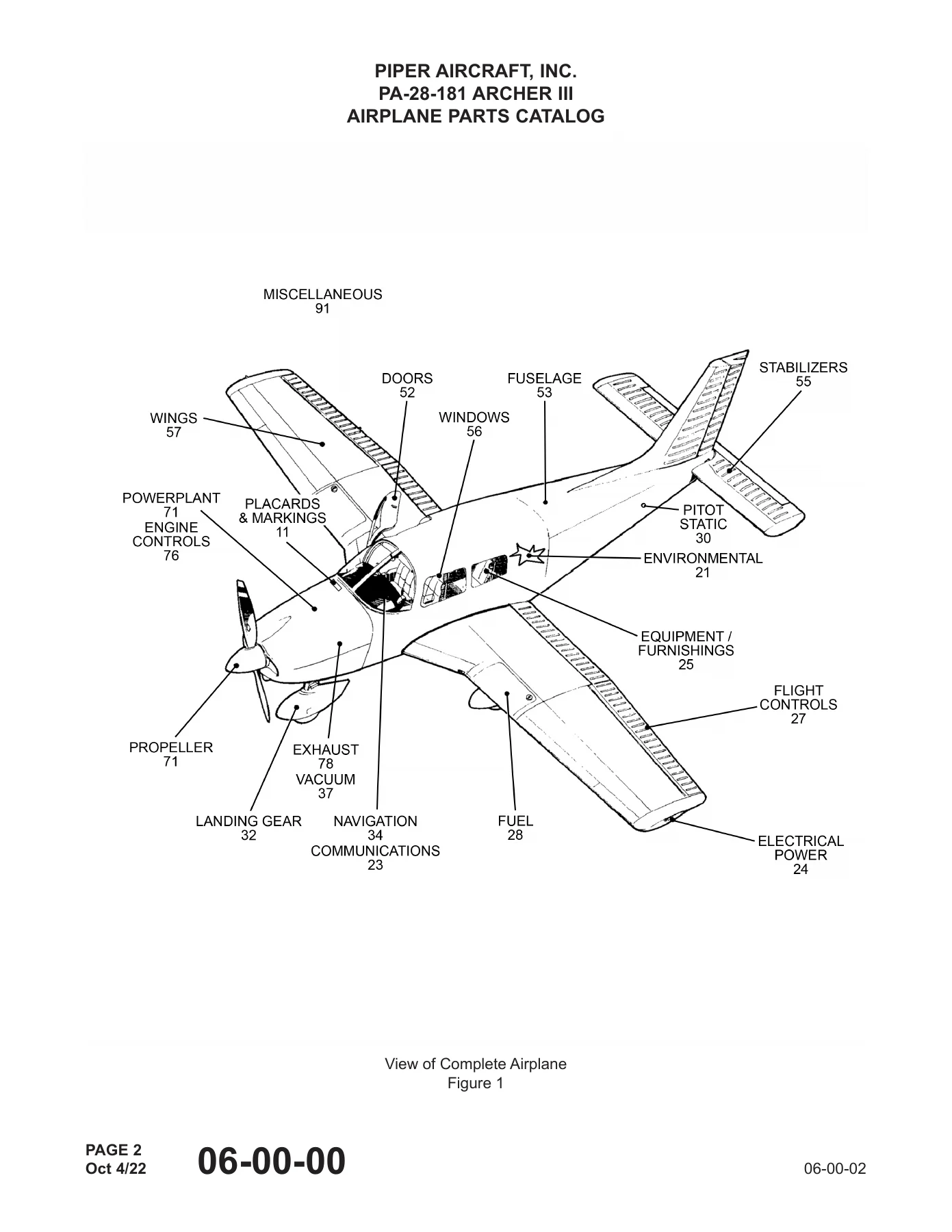
  • Chapter 6 – Complete Airplane (general breakdown view)
  • Chapter 11 – Placards and Markings (exterior and interior)
  • Chapter 21 – Environmental Systems (distribution, pressurization control, heating, cooling, temperature control)
  • Chapter 23 – Communications (speech communications, audio integrating, static discharging)
  • Chapter 24 – Electrical Power (DC generation, external power, load distribution)
  • Chapter 25 – Equipment/Furnishings (flight compartment, passenger compartment, cargo, emergency)
  • Chapter 27 – Flight Controls (aileron and tab, rudder and tab, elevator and tab, horizontal stabilizer, flaps)
  • Chapter 28 – Fuel (storage, distribution, indicating)
  • Chapter 30 – Ice and Rain Protection (airfoil, pitot and static, windows/windshields, propeller)
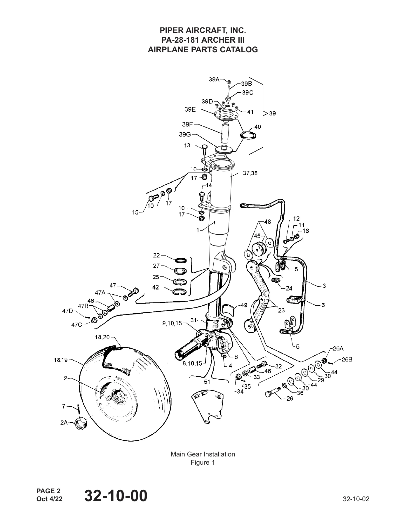
  • Chapter 32 – Landing Gear (main gear and doors, nose gear and doors, extension/retraction, wheels and brakes, steering, position and warning)
  • Chapter 34 – Navigation (flight environment data, attitude and direction, landing/taxiing aids, position determining)
  • Chapter 37 – Vacuum (distribution, indicating)
  • Chapter 52 – Doors (passenger/crew, emergency exit)
  • Chapter 53 – Fuselage (fuselage sections)
  • Chapter 55 – Stabilizers (horizontal stabilizer, elevator, vertical stabilizer, rudder)
  • Chapter 56 – Windows (flight compartment, cabin, door)
  • Chapter 57 – Wings (attach fittings, flight surfaces)
  • Chapter 71 – Powerplant (cowling, mounts, fire seals, air intakes, drains)
  • Chapter 76 – Engine Controls (power control)
  • Chapter 78 – Exhaust (collector/nozzle)
  • Chapter 91 – Miscellaneous (optional equipment kits, repair kits, special tools)

Complete PDF Bookmark Tree

Complete Bookmarks

The complete bookmarks in the “Piper PA-28-181 Archer III Illustrated Parts Catalog – Serial Numbers 2843001 & Up, 2881001 & Up” are as follows:

AIRPLANE PARTS CATALOG (Part Number: 761-898)p. 1
REVISIONS STATUSp. 3
LIST OF EFFECTIVE PAGESp. 5
TABLE OF CONTENTSp. 7
INTRODUCTIONp. 9
How To Identify A Partp. 10
How To Order Partsp. 10
Alternate Part Numbersp. 10
General Informationp. 10
Model Serial Number Informationp. 11
Serial Number Explanationp. 11
Effectivity Codesp. 11
Serial Number Indexp. 17
Chapter/Section Index Guidep. 25
CHAPTER 6 – COMPLETE AIRPLANEp. 31
LIST OF EFFECTIVE PAGESp. 33
TABLE OF CONTENTSp. 35
06-00-00 – VIEW OF COMPLETE AIRPLANEp. 37
Figure 1 – View of Complete Airplanep. 38
CHAPTER 11 – PLACARDS AND MARKINGSp. 41
LIST OF EFFECTIVE PAGESp. 43
TABLE OF CONTENTSp. 45
11-10-00 – PLACARDS AND EXTERIOR STENCILSp. 47
Figure 1 – Placards and Exterior Stencilsp. 48
CHAPTER 21 – ENVIRONMENTAL SYSTEMSp. 55
LIST OF EFFECTIVE PAGESp. 57
TABLE OF CONTENTSp. 59
21-20-00 – DISTRIBUTIONp. 62
Figure 1 – Fresh Air Ventilation Installationp. 62
21-40-00 – HEATINGp. 66
Figure 1 – Cabin Heat and Defroster Installationp. 66
21-50-00 – COOLINGp. 72
Figure 1 – Air Conditioning Compressor, Refrigerant Lines and Alternator Installationp. 72
Figure 2 – Air Conditioning Duct and Evaporator Installationp. 78
Figure 3 – Air Conditioning Condenser Installationp. 80
CHAPTER 23 – COMMUNICATIONSp. 85
LIST OF EFFECTIVE PAGESp. 87
TABLE OF CONTENTSp. 89
23-00-00 – GENERALp. 92
Figure 1 – Radio, Antenna System and Static Wicks Installationp. 92
Figure 2 – Antenna and Cable Locations G1000p. 96
Figure 3 – Avionics Cooling Installationp. 100
Figure 4 – Avionics Cooling Installation G1000p. 102
Figure 5 – System Installation – Vision 1000p. 104
Figure 6 – System Installation – Flightcom Audiop. 108
CHAPTER 24 – ELECTRICAL POWERp. 115
LIST OF EFFECTIVE PAGESp. 117
TABLE OF CONTENTSp. 119
24-00-00 – GENERALp. 122
Figure 1 – Overhead Switch Panelp. 122
Figure 2 – Overhead Switch Panel G1000p. 124
Figure 3 – Exterior Lighting Installation G1000p. 128
Figure 4 – Air Conditioning Electrical Installationp. 134
Figure 5 – Air Conditioning Electrical Installation G1000p. 136
Figure 6 – Instrument Panel Installationp. 140
Figure 7 – Instrument Panel Installation G1000p. 144
24-30-00 – DC GENERATIONp. 152
Figure 1 – Battery Installationp. 152
24-40-00 – EXTERNAL POWERp. 158
Figure 1 – Auxiliary Power Receptacle Installationp. 158
24-60-00 – DC ELECTRICAL LOAD DISTRIBUTIONp. 162
Figure 1 – Forward Electrical System Installationp. 162
Figure 2 – Forward Electrical System Installation G1000p. 174
Figure 3 – Instrument Panel Electrical Installationp. 182
Figure 4 – Instrument Panel Electrical Installation (2843598 and up with Entegra)p. 186
Figure 5 – Instrument Panel Electrical Installation – G1000p. 190
Figure 6 – Circuit Breaker Panel G1000p. 198
Figure 7 – Wing & Aft Electrical System Installation and Lightingp. 206
CHAPTER 25 – EQUIPMENT/FURNISHINGSp. 213
LIST OF EFFECTIVE PAGESp. 215
TABLE OF CONTENTSp. 217
25-10-00 – FLIGHT COMPARTMENTp. 220
Figure 1 – Interior Installationp. 220
Figure 2 – Pilot & Co-pilot Seats Installationp. 228
Figure 3 – Seats and Belts Installation (D1,F,H,K,M,P,S)p. 232
Figure 4 – Two-Point, Three-Point Seatbelt Airbag Installationp. 238
Figure 5 – Carpet Installationp. 240
Figure 6 – Vertically Adjustable Front Seats – Back & Framep. 244
Figure 7 – Rear Seats Installationp. 248
Figure 8 – Cabin Door Panel Installationp. 252
25-60-00 – EMERGENCYp. 256
Figure 1 – Emergency Locator Transmitter Installationp. 256
Figure 2 – Emergency Power Supply Installation G1000p. 262
CHAPTER 27 – FLIGHT CONTROLSp. 265
LIST OF EFFECTIVE PAGESp. 267
TABLE OF CONTENTSp. 269
27-10-00 – AILERON & TABp. 272
Figure 1 – Control System Installationp. 272
Figure 2 – Control Wheel Installationp. 276
27-20-00 – RUDDER & TABp. 280
Figure 1 – Rudder Pedal Installationp. 280
Figure 2 – Rudder Trim Mechanism Installationp. 282
27-30-00 – ELEVATOR & TABp. 286
Figure 1 – Stabilator Trim Installationp. 286
27-50-00 – FLAPSp. 290
Figure 1 – Flap Control Installationp. 290
CHAPTER 28 – FUELp. 297
LIST OF EFFECTIVE PAGESp. 299
TABLE OF CONTENTSp. 301
28-10-00 – STORAGEp. 304
Figure 1 – Fuel Tank Assyp. 304
28-20-00 – DISTRIBUTIONp. 308
Figure 1 – Forward Fuel System Installation, Carbureted Engine (A,B,C,D,D1,E,F,G,H,N,P)p. 308
Figure 2 – Forward Fuel System Installation, Fuel Injected Engine (K,L,M,R,S)p. 312
Figure 3 – Aft Fuel System Installationp. 318
Figure 4 – Aft Fuel System Installation (R,S)p. 320
CHAPTER 30 – ICE AND RAIN PROTECTIONp. 323
LIST OF EFFECTIVE PAGESp. 325
TABLE OF CONTENTSp. 327
30-30-00 – PITOT AND STATICp. 330
Figure 1 – Pitot Static System Installationp. 330
Figure 2 – Pitot Static System Installation NXip. 334
Figure 3 – Pitot Static System Installation G1000 Instrument Panelp. 340
CHAPTER 32 – LANDING GEARp. 345
LIST OF EFFECTIVE PAGESp. 347
TABLE OF CONTENTSp. 349
32-00-00 – GENERALp. 352
Figure 1 – Main and Nose Wheel Fairing Installationp. 352
32-10-00 – MAIN GEAR AND DOORSp. 356
Figure 1 – Main Gear Installationp. 356
Figure 2 – Main Landing Gear Strut Fairing Installationp. 360
32-20-00 – NOSE GEAR AND DOORSp. 364
Figure 1 – Nose Gear Installationp. 364
Figure 2 – Nose Gear Strut Assyp. 368
32-40-00 – WHEELS AND BRAKESp. 372
Figure 1 – Main Wheel Assyp. 372
Figure 2 – Nose Wheel Assy (Cleveland)p. 374
Figure 3 – Nose Wheel Assy (McCauley)p. 376
Figure 4 – Brake Assyp. 378
Figure 5 – Toe Brake Installationp. 380
Figure 6 – Toe Brake Master Cylinder Assyp. 384
Figure 7 – Hand Brake Installationp. 386
CHAPTER 34 – NAVIGATIONp. 389
LIST OF EFFECTIVE PAGESp. 391
TABLE OF CONTENTSp. 393
34-00-00 – GENERALp. 396
Figure 1 – Magnetometer & Miscellaneous Entegra Avionics Equipmentp. 396
Figure 2 – System Installation – G1000, AHRS and ADCp. 400
Figure 3 – System Installation – Aspen EFD1000 Standby Instrumentp. 404
Figure 4 – System Installation – Garmin G5 Electronic Flight Instrumentp. 410
Figure 5 – System Installation – KN 63 DMEp. 416
Figure 6 – System Installation – KR 87 ADFp. 420
Figure 7 – System Installation – GTS 800 TASp. 424
Figure 8 – System Installation – GDL 69A XM Weather/Musicp. 428
Figure 9 – System Installation – GDL 59p. 432
Figure 10 – System Installation – GSU 75p. 436
Figure 11 – Manual Electric Trim Installationp. 442
Figure 12 – 55X Autopilot Installation – Overviewp. 446
Figure 13 – System Installation – GFC 700 Autopilotp. 458
Figure 14 – Encoder Installationp. 464
Figure 15 – System Installation – AOA Indicatorp. 466
Figure 16 – System Installation – Wet Compassp. 468
CHAPTER 37 – VACUUMp. 471
LIST OF EFFECTIVE PAGESp. 473
TABLE OF CONTENTSp. 475
37-00-00 – GENERALp. 478
Figure 1 – Vacuum System Installationp. 478
Figure 2 – Auxiliary Vacuum System Installationp. 480
CHAPTER 52 – DOORSp. 485
LIST OF EFFECTIVE PAGESp. 487
TABLE OF CONTENTSp. 489
52-10-00 – PASSENGER/CREWp. 492
Figure 1 – Fuselage Cabin and Baggage Door Installationp. 492
Figure 2 – Door Installation (T,U,V,W)p. 496
Figure 3 – Cabin Door Installation (T,U,V,W)p. 498
Figure 4 – Baggage Door Installation (T,U,V,W)p. 504
CHAPTER 53 – FUSELAGEp. 509
LIST OF EFFECTIVE PAGESp. 511
TABLE OF CONTENTSp. 513
53-10-00 – FUSELAGEp. 516
Figure 1 – Fuselage Assy – Completep. 516
Figure 2 – Fuselage Upper Forward Cockpit Assyp. 520
Figure 3 – Fuselage Upper Center Cockpit Assyp. 524
Figure 4 – Fuselage Lower Forward Cockpit Assyp. 528
Figure 5 – Fuselage Lower Aft Cockpit Assyp. 532
Figure 6 – Fuselage Aft Sectionp. 534
Figure 7 – Fuselage Assembly – Complete (T,U,V,W)p. 538
Figure 8 – Cabin Assembly (T,U,V,W)p. 544
Figure 9 – Cockpit Assembly (T,U,V,W)p. 548
Figure 10 – Lower Forward Assembly (T,U,V,W)p. 554
Figure 11 – Lower Aft Assembly (T,U,V,W)p. 560
Figure 12 – Tailcone Assembly (T,U,V,W)p. 564
CHAPTER 55 – STABILIZERSp. 569
LIST OF EFFECTIVE PAGESp. 571
TABLE OF CONTENTSp. 573
55-00-00 – GENERALp. 576
Figure 1 – Tail Surfaces Installationp. 576
55-10-00 – HORIZONTAL STABILIZERp. 580
Figure 1 – Stabilator Assyp. 580
55-30-00 – VERTICAL STABILIZERp. 584
Figure 1 – Fin Assyp. 584
55-40-00 – RUDDERp. 588
Figure 1 – Rudder Assyp. 588
CHAPTER 56 – WINDOWSp. 591
LIST OF EFFECTIVE PAGESp. 593
TABLE OF CONTENTSp. 595
56-10-00 – FLIGHT COMPARTMENTp. 598
Figure 1 – Fuselage Enclosure Installationp. 598
Figure 2 – Windshield Installation (T,U,V,W)p. 602
CHAPTER 57 – WINGSp. 605
LIST OF EFFECTIVE PAGESp. 607
TABLE OF CONTENTSp. 609
57-40-00 – LEADING EDGE AND LEADING EDGE DEVICESp. 612
Figure 1 – Wing Installationp. 612
57-50-00 – TRAILING EDGE AND TRAILING EDGE DEVICESp. 620
Figure 1 – Wing Leading Edge Assemblyp. 620
Figure 2 – Wing Trailing Edge Assyp. 624
Figure 3 – Aileron Assyp. 628
Figure 4 – Flap Assyp. 630
CHAPTER 71 – POWERPLANTp. 633
LIST OF EFFECTIVE PAGESp. 635
TABLE OF CONTENTSp. 637
71-10-00 – COWLINGp. 640
Figure 1 – Powerplant Installationp. 640
Figure 2 – Engine Baffle Installationp. 646
Figure 3 – Engine Cowl Installationp. 650
Figure 4 – Second Oil Cooler Installationp. 654
Figure 5 – Surestart Mag Booster Installationp. 656
CHAPTER 76 – ENGINE CONTROLSp. 659
LIST OF EFFECTIVE PAGESp. 661
TABLE OF CONTENTSp. 663
76-10-00 – POWER CONTROLp. 666
Figure 1 – Engine Controls Installationp. 666
CHAPTER 78 – EXHAUSTp. 671
LIST OF EFFECTIVE PAGESp. 673
TABLE OF CONTENTSp. 675
78-10-00 – COLLECTOR/NOZZLEp. 678
Figure 1 – Engine Exhaust System Installationp. 678
CHAPTER 91 – MISCELLANEOUSp. 681
LIST OF EFFECTIVE PAGESp. 683
TABLE OF CONTENTSp. 685
91-10-00 – MISCELLANEOUSp. 687
Service and Optional Kitsp. 687
Foreign Certification Requirementsp. 690

Together these chapters give a technician or owner a chapter-by-chapter breakdown of every major structural section, control surface, and system on the Archer III, each illustrated with an exploded assembly figure and a matching parts list showing part numbers, nomenclature, quantity required, and serial number effectivity.

How the Parts Lists Work

Every figure in this Piper PA-28-181 Archer III Illustrated Parts Catalog is paired with a numbered parts list. The Figure and Index Number column ties each callout on the diagram to its row in the list, the Part Number column gives the exact number to use when ordering, and indentation with asterisks shows how sub-components nest inside a next-higher assembly. A Serial Numbers Affected column and a set of effectivity codes (A through W) flag which parts apply to which serial number ranges and avionics configuration, so buyers with a G1000, NXi, or Entegra-equipped Archer III can identify the correct part for their specific airplane rather than guessing from a generic listing.

IMAGES PREVIEW

Piper PA-28-181 Archer III Illustrated Parts Catalog - Serial Numbers 2843001 & Up, 2881001 & Up — PDF page 1 preview
Piper PA-28-181 Archer III Illustrated Parts Catalog - Serial Numbers 2843001 & Up, 2881001 & Up — PDF page 38 preview
Piper PA-28-181 Archer III Illustrated Parts Catalog - Serial Numbers 2843001 & Up, 2881001 & Up — PDF page 356 preview

Get the Right Part the First Time

This catalog lets an owner, mechanic, or parts department confirm the correct part number, description, and effectivity before placing an order for a Piper PA-28-181 Archer III — cutting down on returns caused by ordering the wrong revision of a part. Because factory documentation ties parts to exact serial number ranges and avionics fit, working from this Illustrated Parts Catalog helps ensure replacement hardware, fairings, control surface components, landing gear parts, and interior fittings match the airplane’s actual configuration. The PDF downloads instantly after purchase, needs no shipping, and can be viewed on a phone, tablet, laptop, or hangar computer, or printed as needed for shop reference.
Reviews

There are no reviews yet.

Be the first to review “Piper PA-28-181 Archer III Illustrated Parts Catalog – Serial Numbers 2843001 & Up, 2881001 & Up”

What Our Customers Say

★★★★★ Live reviews from customers
Loading customer reviews...
0
    0
    Your Cart
    Your cart is emptyReturn to Shop
    🛒
    Recently Purchased
    🕒 verified order