
Piper PA-28-236 Dakota Maintenance Manual – Part Number 761-681
Original price was: $39.95.$24.95Current price is: $24.95.
Official factory maintenance manual for the Piper PA-28-236 Dakota, covering airframe systems, scheduled inspections, servicing, air conditioning, and electrical overhaul.
Description
Factory Service & Shop Instructions for Piper PA-28-236 Dakota
The Piper PA-28-236 Dakota Maintenance Manual – Part Number 761-681 provides comprehensive airframe, system, and component maintenance procedures prepared in accordance with the General Aviation Manufacturers Association (GAMA) standard format. Covering all production model years from 1979 through 1986 and subsequent serial numbers, this technical publication serves as the authoritative shop reference for certificated aircraft mechanics, repair stations, and owner-operators performing routine servicing, periodic inspections, unscheduled condition checks, and complete component overhauls.
File Details
- Manual Type: Aircraft Maintenance Manual (Card 1 of 3, GAMA Specification)
- Aircraft Manufacturer: Piper Aircraft Corporation
- Applicable Model: Piper PA-28-236 Dakota
- Document Part Number: 761 681 (761-681)
- Reissue & Revision Status: Reissued August 1, 1986 with Interim Revisions through February 15, 1995
- Covered Serial Number Ranges: 28-7911001 through 28-7911395 (1979), 28-8011001 through 28-8011161 (1980), 28-8111001 through 28-8111105 (1981), 28-8211001 through 28-8211060 (1982), 28-8311001 through 28-8311025 (1983), 28-8411001 through 28-8411031 (1984), 28-8511001 through 28-8511020 (1985), 28-8611001 through 28-8611008 (1986), and serial numbers 2811001 and up
- Engine Installation: Avco Lycoming O-540-J3A5D (235 hp at 2400 rpm)
- Propeller Installation: Hartzell Constant Speed Hub HC-F2YR-1() with Blade F8468A-4R and F-4-21() Governor
- Language: English
- Page Count: 616 pages
- Format: High-resolution digital PDF download
Chapters Covered
- Chapter 4 – Airworthiness Limitations: FAA-approved Part 43 and Part 91 inspection requirements, structural fatigue safe-life parameters, and Hartzell propeller blade safe-life limits.
- Chapter 5 – Time Limits / Maintenance Checks: Inspection requirements for 50-hour, 100-hour/annual, 500-hour, and 1000-hour intervals across Propeller, Engine, Cabin, Fuselage/Empennage, Wing, Landing Gear, and Operational groups; overlimits inspections for hard or overweight landings, severe turbulence encounters, and engine sudden stoppage; programmed inspection scheduling under P/N 761 734.
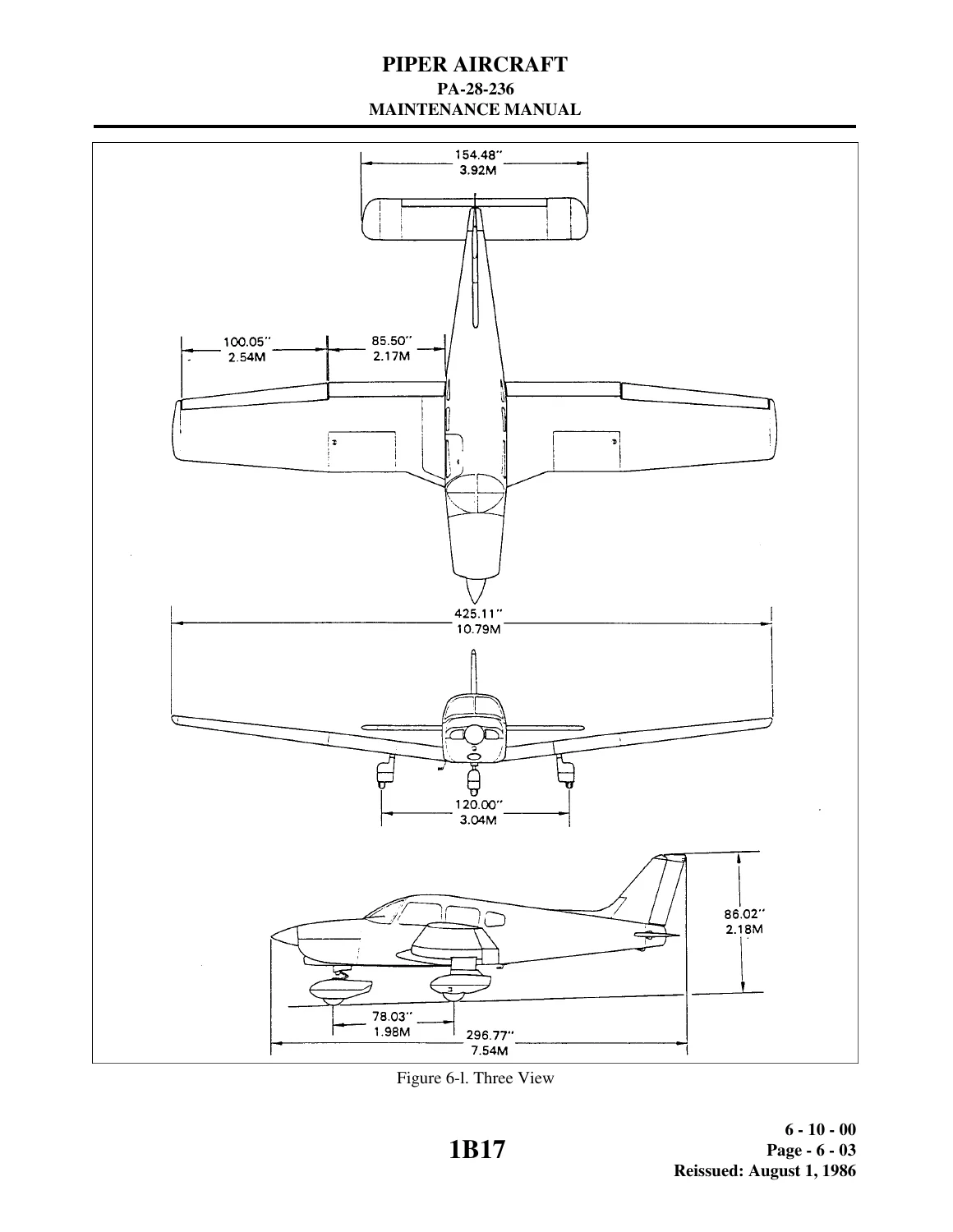
- Chapter 6 – Dimensions and Areas: Chart 601 leading particulars and principal dimensions; 3-view engineering drawings; station reference datum lines including fuselage stations (FS), buttock lines (BL), and water lines (WL); exterior access and inspection plate locations.
- Chapter 7 – Lifting and Shoring: Main gear jack pad arrangements on front wing spars, tail skid support cradles, and mandatory 250-pound tail ballast procedures.
- Chapter 8 – Leveling and Weighing: Longitudinal leveling screw locations below left front window, lateral leveling across rear seat spar box, wheel scale positioning, and ramp tare procedures.
- Chapter 9 – Towing and Taxiing: Nose gear towing bar limits, maximum turning angles, tractor towing safety, and engine run-up precautions over loose gravel.
- Chapter 10 – Parking and Mooring: Parking brake ratchet operation, gust lock installations using front seat belts, and 45-degree three-point tie-down procedures.
- Chapter 11 – Required Placards: Complete exterior decal mapping and internal instrument panel, console, circuit breaker, and emergency bus switch markings.
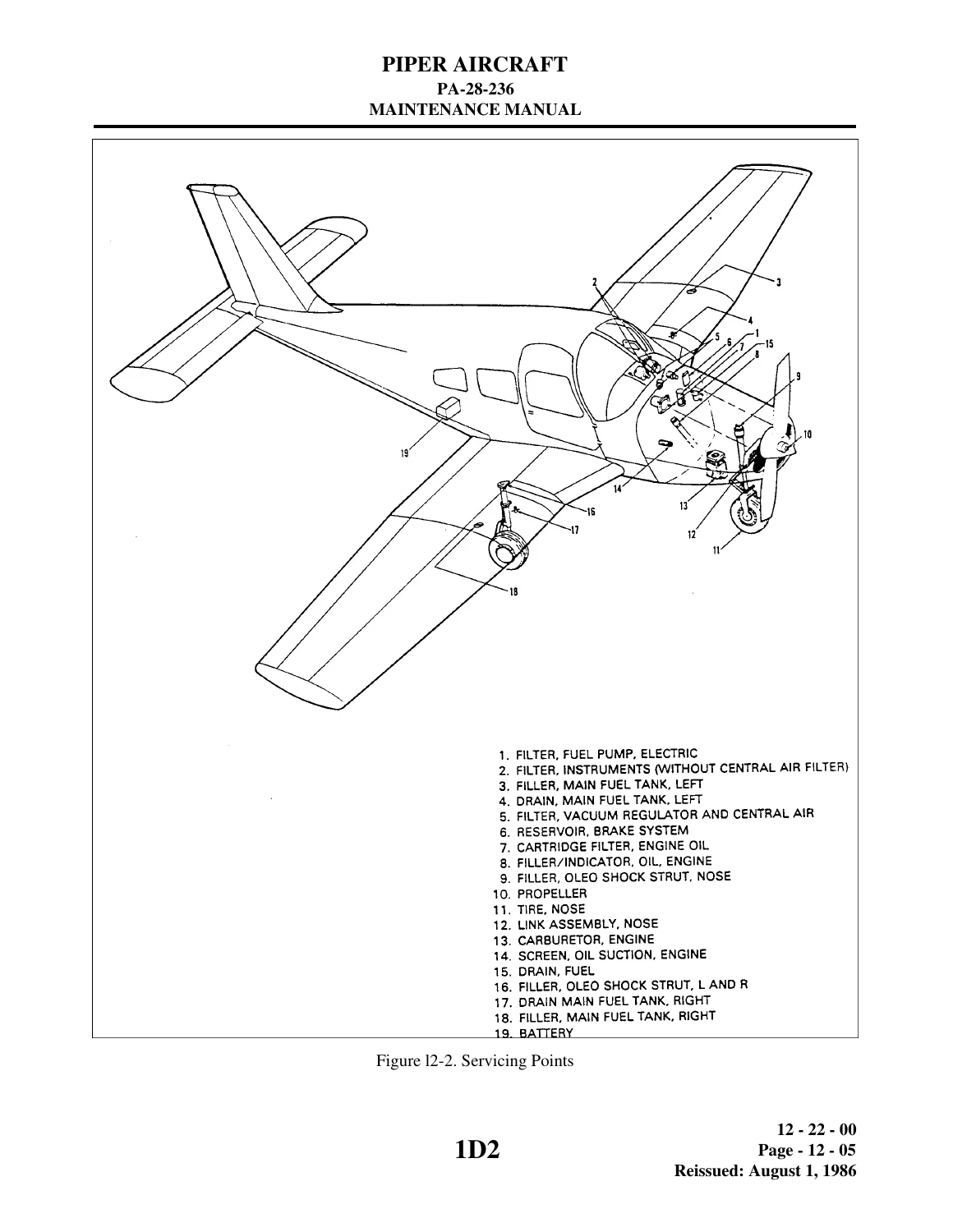
- Chapter 12 – Servicing: Fuel system draining, 77-gallon capacity specifications, MIL-I-27686 anti-icing fuel additive blending; Lycoming 12-quart oil sump draining, suction screen cleaning, full-flow cartridge filter replacement; nose and main landing gear air-oil oleo strut fluid servicing (Methods I and II), 250 psi nitrogen inflation, Cleveland brake reservoir replenishment; dry-air induction filter cleaning; constant speed propeller lubrication; battery box neutralization; comprehensive airframe lubrication schedules.
- Chapter 20 – Standard Practices – Airframe: Torque wrench adapter formulas, rod end bearing alignment, Cherrylock blind rivet extraction, fluid line color coding and markings, flareless tube fitting presetting, metal corrosion removal, chemical surface treatments, and exterior finishing specifications (DuPont Imron, Randolph Ranthane, Alumigrip, Titanine, Ameron Jet-Glo, and Randacryl).
- Chapter 21 – Environmental Systems: Exhaust manifold heater muff and defroster ducting; cabin ventilation and overhead blower servicing; complete vapor-cycle air conditioning maintenance including York compressor service, magnetic clutch replacement, condenser door actuator rigging, Ranco pressure relief switch testing, system leak detection, evacuation down to 26-28 inches Hg, and charging stand procedures.
- Chapter 22 – Autoflight: Automated Flight Control Systems (AFCS) vendor cross-references and Piper AutoControl, AutoFlite, and Pitch Trim service literature mapping.
- Chapter 23 – Communications: Avionics master and emergency bus switch circuits; Narco and Communications Components Corp (CCC) Emergency Locator Transmitter (ELT) battery replacement, testing intervals, and radiation sweep restrictions.
- Chapter 24 – Electrical Power: 14-volt DC single-wire negative ground electrical distribution; 12-volt battery testing and charging; voltage regulator and overvoltage relay checks; Chrysler (3656624, 4111810) and Prestolite (ALY-6422) 60-amp alternator complete teardown, rotor field coil current draw checks, C-3829 diode rectifier testing, stator diagnostics, and drive belt tensioning.
Together, these chapters equip the technician with unambiguous technical data, exact assembly clearances, and verified testing procedures. Rather than relying on generic shop manuals, mechanics working with the Piper PA-28-236 Dakota Maintenance Manual can verify manufacturer torque limits, fluid grades, and structural rigging dimensions specifically established for the Lycoming O-540-powered Dakota airframe.
Airframe Inspection Schedules, Servicing & Rigging Procedures
The periodic inspection program outlined in the Piper PA-28-236 Dakota Maintenance Manual provides structured checklists broken down across eight distinct operational zones. From verifying torque link bolt security to checking stabilator control cable tensions beneath the aft baggage floor per Piper Service Bulletin 977 and 856, every task is matched to 50, 100, 500, or 1000-hour intervals. Detailed conditional inspection procedures guide mechanics through post-incident airworthiness checks following hard landings, heavy turbulence, or engine overspeed, detailing precise spar web, bulkhead, and skin wrinkle inspection zones.
Chapter 12 provides thorough handling procedures for all recurring fluid services. It details nose gear strut servicing to maintain 3.25 inches (+/- 0.25 in) of exposed piston tube and main gear oleo strut servicing to maintain 4.50 inches (+/- 0.50 in) under normal static load. Technicians will find step-by-step instructions for both gravity and pressure filling methods using MIL-H-5606 hydraulic fluid, followed by nitrogen inflation to 250 psi (+/- 25 psi). Induction air filtration procedures outline cleaning parameters using Donaldson D-1400 compound, while power plant servicing includes detailed oil change guidelines for mineral and ashless dispersant grades under Lycoming Service Instruction 1014.
Environmental Systems & Vapor-Cycle Air Conditioning Overhaul
A major technical highlight within this Piper PA-28-236 Dakota service manual is the comprehensive coverage of the cabin climate and optional vapor-cycle cooling installations. In addition to exhaust shroud heater maintenance and carbon monoxide contamination thresholds (limited to less than 1 part in 20,000), Chapter 21 provides unmatched depth on R-12 refrigeration servicing. Detailed schematics illustrate the York compressor installation, magnetic clutch shimming, and receiver-dehydrator placement aft of the baggage compartment.
Mechanics will find precise rigging instructions for the electrically actuated condenser scoop door on the fuselage belly, requiring 5.00 inches (+/- 0.50 in) of door travel, a 0.16-inch trailing edge gap, and a 0.12-inch mechanism preloading adjustment on the closed limit switch. The manual outlines step-by-step system leak checks with electronic halogen detectors at 50 psi static charge, vacuum dehydration targeting 26 to 28 inches of mercury, and exact refrigerant recharging procedures using the Kent-Moore J23500 charging stand or aircraft engine run-up methods.
DC Electrical Generation, Alternator Diagnostics & Overhaul
Chapter 24 provides complete shop overhaul instructions for the 14-volt charging system, covering both Prestolite ALY-6422 and Chrysler 60-amp alternators. Technicians have access to comprehensive troubleshooting charts addressing tripped 5-amp ALT FIELD circuit breakers, ammeter fluctuations, and shorted output diodes. Step-by-step test benches detail rotor current draw (4.5 to 6.5 amperes at 12 volts for Chrysler; 2.4 to 4.0 amperes for Prestolite), slip ring resistance ranges (1.5 to 2.0 ohms normal, up to 3.0 ohms hot), and stator continuity checks.
Bench teardown guides illustrate specialized pullers (C-4068, C-4201, C-3858), bearing press fitting limits (up to 6800 pounds maximum pressure), and diode testing using the Kent-Moore C-3829 tester or test lamp assemblies. Additional sections guide the technician through proper alternator and compressor drive belt tensioning across Gates and Deco belts, pulley misalignment measurements relative to the ring gear datum, and avionics emergency bus switch verification.
Professional Shop Capability & Instant PDF Delivery
Whether you are performing an annual inspection, tracking down an intermittent electrical fault, rebuilding oleo shock struts, or calibrating flight control stops, the Piper PA-28-236 Dakota Maintenance Manual – Part Number 761-681 delivers the exact engineering specifications required to maintain your aircraft to FAA standards. Relying on original factory documentation ensures correct rigging angles, proper thread lubricants (such as Parker 6PB and MIL-T-5544), and strict compliance with airframe service bulletins, safeguarding both flight safety and aircraft asset value.
Delivered as an instant PDF download, this manual eliminates costly delays and shipping fees. The digital file is fully indexed, easy to navigate, and viewable across any computer, laptop, tablet, or mobile device. Operators and maintenance shops can easily print specific chapters, inspection checklists, or full wiring diagrams to carry directly into the hangar or keep beside the aircraft on the ramp.
Reviews
There are no reviews yet.