Description
Piper PA-31 Navajo Parts Catalog – 1994 Edition
This is the complete Piper Parts Catalog covering the PA-31 Navajo, PA-31-300 Navajo 300, PA-31-310 Navajo, and PA-31-325 Navajo C/R aircraft. Published under part number 753 703 and revised February 18, 1994, this illustrated parts manual gives you the exact part numbers, nomenclature, quantities, and serial number applicability for every major assembly and system on these twin-engine aircraft.
File Details
- Manual Type: Illustrated Parts Catalog
- Brand: Piper Aircraft Corporation
- Models Covered: PA-31 Navajo, PA-31-300 Navajo 300, PA-31-310 Navajo, PA-31-325 Navajo C/R
- Part Number: 753 703
- Revision Date: February 18, 1994
- Language: English
- File Format: PDF
- Page Count: 1,036 pages
- Original Publication: September 20, 1974 (with revisions through 1994)
Complete PDF Bookmark Tree
Complete Bookmarks
The complete bookmarks in the “Piper PA-31 Navajo 300 310 325 Parts Catalog 1994 – Illustrated Aircraft Parts Manual PDF” are as follows:
+753-703 – NAVAJO PARTS CATALOG – PA-31 NAVAJO, PA-31-300 NAVAJO 300 & PA-31-325 NAVAJO C/Rp. 1
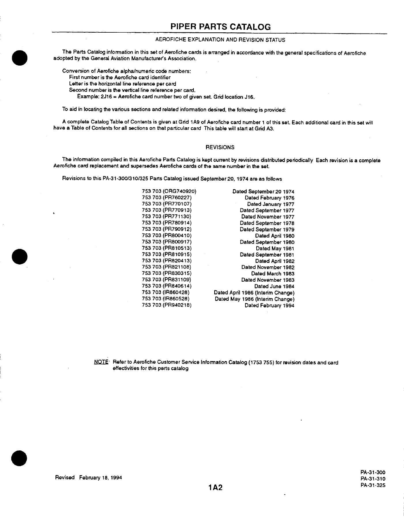
AEROFICHE EXPLANATION AND REVISION STATUSp. 2
INTRODUCTIONp. 3
TABLE OF CONTENTSp. 9
FIGURE 1. VIEW OF COMPLETE AIRPLANEp. 15
+SECTION I – WING GROUPp. 16
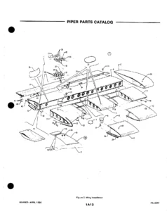
FIGURE 2. WING INSTALLATIONp. 16
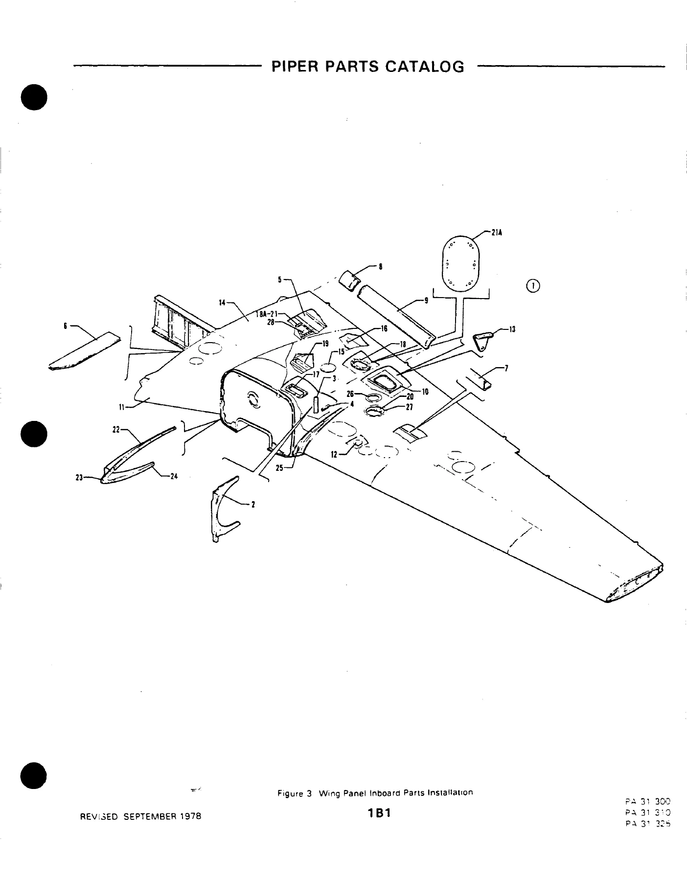
FIGURE 3. WING PANEL INBOARD PARTS INSTALLATIONp. 23
FIGURE 4. WING PANEL OUTBOARD PARTS INSTALLATIONp. 27
FIGURE 5. WING PANEL LEADING EDGE ASSEMBLYp. 31
FIGURE 6. LEADING EDGE SPAR ASSEMBLYp. 35
FIGURE 7. WING PANEL REAR SPAR ASSEMBLYp. 40
FIGURE 8. AILERON ASSEMBLYp. 49
FIGURE 9. FLAP ASSEMBLYp. 53
+SECTION II – FUSELAGE GROUPp. 57
FIGURE 10. FUSELAGE ASSEMBLYp. 57
FIGURE 11. FUSELAGE UPPER FORWARD SECTION ASSEMBLYp. 64
FIGURE 12. FUSELAGE UPPER CABIN SECTION ASSEMBLY (SERIAL NOS. 31-5 TO 31-7612110 INCL)p. 68
FIGURE 12A. FUSELAGE UPPER CABIN SECTION (SERIAL NOS 31-7712001 AND UP)p. 72
FIGURE 13. PILOT DOOR FUSELAGE FRAME INSTALLATIONp. 76
FIGURE 14. FUSELAGE LOWER FORWARD SECTION ASSEMBLYp. 79
FIGURE 15. FUSELAGE LOWER FORWARD FRAME ASSEMBLYp. 85
FIGURE 16. FUSELAGE LOWER REAR SECTION ASSEMBLYp. 90
FIGURE 17. FUSELAGE LOWER CENTER FRAME ASSEMBLYp. 95
FIGURE 18. FUSELAGE LOWER REAR FRAME ASSEMBLYp. 98
FIGURE 19. CARGO DOOR FUSELAGE FRAME INSTALLATIONp. 101
FIGURE 20. FUSELAGE AFT SECTION (STA. 244 TO STA. 352)p. 106
FIGURE 21. FUSELAGE AFT SECTION (STA. 317.75 TO STA. 352)p. 112
FIGURE 22. FLOORBOARD INSTALLATIONp. 116
FIGURE 23. WINSHIELD INSTALLATIONp. 120
FIGURE 24. WINDOW INSTALLATION (SERIAL NOS. 31-5 TO 31-7612110 INCL)p. 123
FIGURE 24A. WINDOW INSTALLATION (SERIAL NOS. 31-7712001 AND UP)p. 129
FIGURE 25. EMERGENCY EXIT WINDOW INSTALLATIONp. 133
FIGURE 26. CABIN ENTRANCE DOOR INSTALLATIONp. 138
FIGURE 27. UPPER CABIN ENTRANCE DOORp. 142
FIGURE 28. LOWER CABIN ENTRANCE DOORp. 145
FIGURE 29. FORWARD BAGGAGE DOOR INSTALLATIONp. 153
FIGURE 30. CARGO DOOR ASSEMBLY AND INSTALLATIONp. 157
FIGURE 31. PILOT DOOR INSTALLATIONp. 162
FIGURE 32. PILOT DOOR ASSEMBLY (COMPLETE)p. 166
+SECTION III – TAIL SURFACES GROUPp. 171
FIGURE 33. TAIL SURFACES INSTALLATIONp. 171
FIGURE 34. FIN ASSEMBLYp. 177
FIGURE 35. RUDDER ASSEMBLYp. 181
FIGURE 36. STABILIZER ASSEMBLYp. 185
FIGURE 37. ELEVATOR ASSEMBLYp. 189
+SECTION IV – LANDING GEAR GROUPp. 194
FIGURE 38. MAIN LANDING GEAR INSTALLATIONp. 194
FIGURE 39. MAIN GEAR STRUT ASSEMBLYp. 201
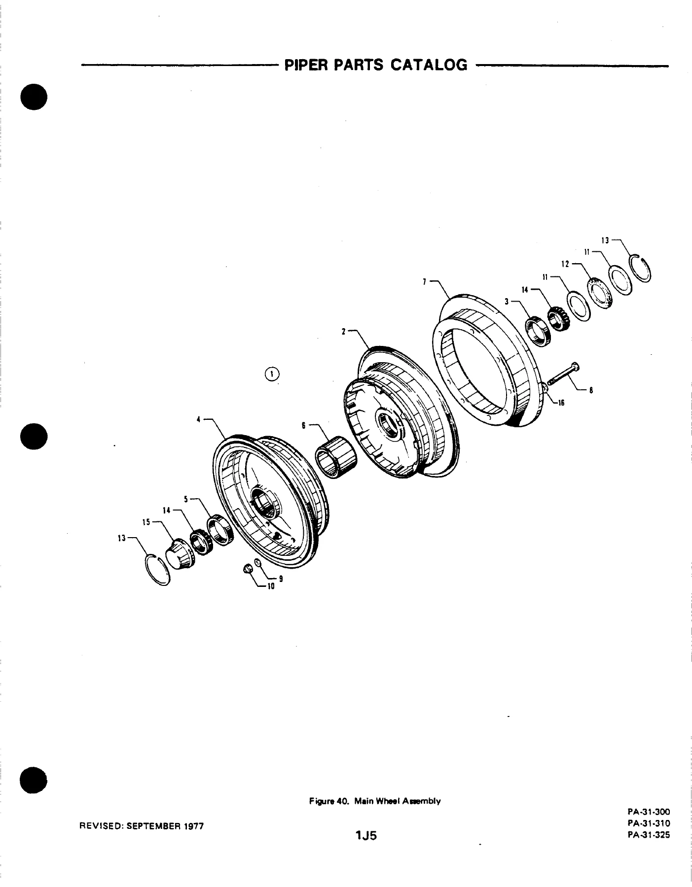
FIGURE 40. MAIN WHEEL ASSEMBLYp. 205
FIGURE 41. MAIN WHEEL BRAKE ASSEMBLYp. 208
FIGURE 41A. MAIN WHEEL BRAKE ASSEMBLY (SERIAL NOS 31-7812001 AND UP)p. 211
FIGURE 42. NOSE LANDING GEAR INSTALLATIONp. 214
FIGURE 43. NOSE GEAR STRUT ASSEMBLYp. 219
FIGURE 44. NOSE WHEEL ASSEMBLYp. 225
FIGURE 45. NOSE GEAR STEERING MECHANISM INSTALLATIONp. 228
FIGURE 46. BRAKE SYSTEM INSTALLATIONp. 231
FIGURE 47. DUAL BRAKE INSTALLATIONp. 235
FIGURE 48. MASTER CYLINDER AND PARKING BRAKE VALVEp. 238
+SECTION V – CABIN EQUIPMENT GROUPp. 246
FIGURE 49. CABIN INTERIOR FINISHING INSTALLATION (SERIAL NOS. 31-5 TO 31-7300923 INCL)p. 246
FIGURE 50. CABIN INTERIOR FINISHING INSTALLATION (SERIAL NOS 31-7300924 TO 31-7612110 INCL)p. 257
FIGURE 50A. CABIN INTERIOR FINISHING INSTALLATION (SERIAL NUMBERS 31-7712001 TO 31-7812033 INCL)p. 262
FIGURE 50B. CABIN INTERIOR FINISHING INSTALLATION (SERIAL NUMBERS 31-7812034 AND UP)p. 266
FIGURE 51. CABIN INTERIOR FINISHING INSTALLATION (FOR AIR CONDITIONING ONLY) (SERIAL NOS. 31-752 TO 31-7612110 INCL)p. 270
FIGURE 51A. CABIN INTERIOR FINISHING INSTALLATION (FOR AIR CONDITIONING ONLY) (SERIAL NOS 31-7712001 TO 31-7812033 INCL)p. 275
FIGURE 51B. CABIN INTERIOR FINISHING INSTALLATION (FOR AIR CONDITIONING ONLY) (SERIAL NOS. 31-7812034 AND UP)p. 278
FIGURE 52. CARGO BARRIER EQUIPMENT INSTALLATIONp. 281
FIGURE 53. CABIN HEADLINING PANELS INSTALLATIONp. 284
FIGURE 54. FLOOR CARPET INSTALLATIONp. 290
FIGURE 55. BAGGAGE COMPARTMENT FINISHING INSTALLATIONp. 296
FIGURE 56. CABIN FURNISHINGS INSTALLATION (SERIAL NUMBERS 31-7712001 AND UP)p. 300
FIGURE 56A. CREW SEATS INSTALLATION (SERIAL NOS. 31-5 TO 31-7612110 INCL)p. 309
FIGURE 56B. CREW SEATS INSTALLATION (SERIAL NOS. 31-7712001 AND UP)p. 317
FIGURE 57. PASSENGER SEATS INSTALLATION (SERIAL NOS. 31-5 TO 31-7612110 INCL)p. 323
FIGURE 57A. PASSENGER SEATS INSTALLATION (FORWARD FACING) (SERIAL NOS 31-7712001 AND UP)p. 332
FIGURE 58. SEATS INSTALLATION, THIRD AND FOURTH, AFT FACING (SERIAL NOS. 31-7712001 AND UP)p. 338
FIGURE 58A. 7TH AND 8TH SEAT INSTALLATION (SERIAL NOS 31-5 TO 31-7612110 INCL)p. 344
FIGURE 58B. 7TH SEAT INSTALLATION (SERIAL NOS 31-7712001 AND UP)p. 351
FIGURE 58C. 8TH SEAT INSTALLATION (SERIAL NOS 31-7712001 AND UP)p. 356
FIGURE 58D. SEATS INSTALLATION – EIGHTH (SERIAL NUMBERS 31-81 12001 AND UP)p. 360
FIGURE 59. NINE SEAT INSTALLATION (AZTEC SEATS)p. 364
FIGURE 60. CABIN DIVIDER PANEL AND FIRE EXTINGUISHER INSTALLATION (SERIAL NOS. 31-5 TO 31-7612110 INCL)p. 368
FIGURE 61. FOLDING TABLE, REFRESHMENT CABINET AND BEVERAGE DISPENSER INSTALLATION (SERIAL NOS. 31-5 TO 31-7612110 INCL)p. 371
FIGURE 62. TOILET AND RELIEF TUBE INSTALLATION (SERIAL NOS. 31-5 TO 31-7612110 INCL)p. 374
FIGURE 62A. TOILET INSTALLATION – SIDE FACINGp. 380
FIGURE 62B. TOILET INSTALLATION, 7TH SEAT POSITION (SERIAL NOS 31-7712053 AND UP)p. 384
+SECTION VI – INSTRUMENTS GROUPp. 388
FIGURE 63. INSTRUMENT PANEL INSTALLATIONp. 388
FIGURE 64. DUAL INSTRUMENT PANEL INSTALLATIONp. 395
FIGURE 65. MISCELLANEOUS AIR AND FLUID LINES INSTALLATIONp. 400
FIGURE 66. DUAL INSTRUMENT AIR SYSTEM INSTALLATIONp. 404
FIGURE 67. INSTRUMENT PRESSURE SYSTEM INSTALLATION (SERIAL NOS. 31-5 TO 31-7612018 INCL)p. 407
FIGURE 67A. INSTRUMENT PRESSURE SYSTEM INSTALLATION (SERIAL NOS. 31-7612019 AND UP)p. 412
FIGURE 68. STATIC PRESSURE SYSTEM INSTALATIONp. 417
+SECTION VII – POWER PLANT GROUPp. 11
FIGURE 69. POWER PLANT INSTALLATIONp. 421
FIGURE 70. POWER PLANT INSTALLATIONp. 427
FIGURE 70A. MECHANICAL TACHOMETER SHAFT INSTALLATIONp. 431
FIGURE 71. ENGINE EXHAUST SYSTEM INSTALLATIONp. 434
FIGURE 72. ENGINE BAFFLE INSTALLATIONp. 437
FIGURE 73. 0IL COOLER AND BREATHER SYSTEM INSTALLATIONp. 440
FIGURE 74 OIL COOLER AND BREATHER SYSTEM INSTALLATIONp. 444
FIGURE 75. TWO BLADE PROPELLER ASEMBLYp. 447
FIGURE 76 THREE-BLADE PROPELLER ASSEMBLYp. 451
FIGURE 77. PROPELLER SYNCHRONIZER SYSTEM INSTALLATIONp. 455
FIGURE 78. PROPELLER SYNCHROPHASER SYSTEM INSTALLATION (SERIAL NOS. 31-5 TO 31-7612039 INCL)p. 458
FIGURE 78A. PROPELLER SYNCHROPHASER SYSTEM INSTALLATION (SERIAL NOS 31-7812040 AND UP)p. 461
FIGURE 79. ENGINE CONTROLS INSTALLTIONp. 464
FIGURE 80 ENGINE COWL INSTALLATIONp. 468
FIGURE 81. COWL FLAP ACTUATING MECHANISM INSTALLATIONp. 471
FIGURE 82. NACELLE INSTALLATION (USED IF NACELLE WING LOCKERS ARE NOT INSTALLED)p. 475
FIGURE 83. NACELLE INSTALLATION (USED IF NACELLE WING LOCKERS ARE INSTALLEDp. 480
FIGURE 84. NACELLE LOCKER DOOR ASSEMBLY AND INSTALLATIONp. 485
+SECTION VIII – FUEL SYSTEM GROUPp. 494
FIGURE 85. LEFT ENGINE FUEL SYSTEM INSTALLATIONp. 494
FIGURE 86. LEFT ENGINE FUEL SYSTEM INSTALLATIONp. 499
FIGURE 87. LEFT ENGINE FUEL SYSTEM INSTALLATIONp. 504
FIGURE 88. RIGHT ENGINE FUEL SYSTEM INSTALLATIONp. 508
FIGURE 89. RIGHT ENGINE FUEL SYSTEM INSTALLATIONp. 514
FIGURE 90. RIGHT ENGINE FUEL SYSTEM INSTALLATIONp. 519
FIGURE 91. FUEL FLOW AND PRESSURE GAUGE INSTALLATIONp. 523
FIGURE 92. FUEL FLOW GAUGE INSTALLATIONp. 527
FIGURE 93. FUEL SYSTEM COMPONENTSp. 530
FIGURE 94. EMERGENCY FUEL PUMP ASSEMBLYp. 533
FIGURE 95. FUEL SYSTEM CONTROL PANEL INSTALLATIONp. 538
FIGURE 96. MAIN FUEL CELL AND LINER INSTALLATIONp. 543
FIGURE 97. AUXILIARY FUEL CELL AND LINER INSTALLATIONp. 547
FIGURE 97A. NACELLE FUEL SYSTEM INSTALLATION (NAYAK) (SERIAL NUMBERS 31-8112001 AND UP)p. 551
+SECTION IX – CONTROL SYSTEM GROUPp. 555
FIGURE 98. PEDESTAL INSTALLATIONp. 555
FIGURE 99. PEDESTAL CONTROL ASSEMBLYp. 561
FIGURE 100. ALTERON CONTROL INSTALLATIONp. 565
FIGURE 10.1 AILERON TRIM INSTALLATIONp. 569
FIGURE 102. RUDDER CONTROL INSTALLATIONp. 573
FIGURE 103. RUDDER TRIM INSTALLATIONp. 577
FIGURE 104. ELEVATOR CONTROL INSTALLATIONp. 581
FIGURE 105. ELEVATOR TRIM INSTALLATIONp. 585
FIGURE 106. FLAP CONTROL INSTALLATIONp. 589
FIGURE 107. CONTROL WHEEL INSTALLATIONp. 593
FIGURE 108. CONTROL WHEEL AND BOBWEIGHT INSTALLATIONp. 598
FIGURE 109. RUDDER PADAL INSTALLATIONp. 603
+SECTION X – HYDRAULIC SYSTEM GROUPp. 608
FIGURE 110. FORWARD HYDRAULIC SYSTEM INSTALLATIONp. 608
FIGURE 111. AFT HYDRAULICSYSTEM INSTALLATIONp. 613
FIGURE 112. HYDRAULIC SYSTEM COMPONENTS (OZONE)p. 617
FIGURE 112A. HYDRAULIC SYSTEM COMPONENTS (WIEBEL)p. 621
FIGURE 113. HYDRAULIC POWERPAK ASSEMBLY OZONE)p. 625
FIGURE 113A. HYDRAULIC POWERPAK ASSEMBLY COMPONENTS (OZONE)p. 629
FIGURE 114. HYDRAULIC POWERPK ASSEMBLY (WIEBEL)p. 632
FIGURE 114A. HYDRAULIC POWERPAK ASSEMBLY COMPONENTS (WIEBEL)p. 636
FIGURE 115. LANDING GEAR SELECTOR MECHANISM INSTALLATION (SERIAL NO. 31-5 TO 31-511 INCLUSIVE)p. 639
FIGURE 116. LANDING GEAR SELECTOR MECHANISM INSTALLATION (SERIAL NOS. 31-512 AND UP)p. 642
+SECTION XI – ENVIRONMENTAL GROUPp. 645
FIGURE 117. HEATER AND DEFROSTER SYSTEM INSTALLATIONp. 645
FGURE 118. FORWARD HEATER INSTALLATIONp. 650
FIGURE 119. AFT HEATER INSTALLATIONp. 655
FIGURE 120. HEATER ASSEMBLYp. 659
FIGURE 121. HEATER ASSEMBLY COMPONENTSp. 663
FIGURE 122. VENTILATION SYSTEM INSTALLATION (SERIAL NOS 31-5 TO 31-781229 INCLUSIVE)p. 666
FIGURE 122A. VENTILATION SYSTEM INSTALLATION (SERIAL NOS 31-7912001 AND UP)p. 669
FIGURE 123. CABIN EXHAUST VENT INSTALLATIONp. 673
FIGURE 124. GROUND VENTILATION FAN INSTALLATIONp. 676
FIGURE 125. AIR CONDITIONER EVAPORATOR INSTALLATIONp. 679
FIGURE 126. AIR CONDITIONING FREON SYSTEM INSTALLTIONp. 684
FIGURE 12.7 AIR CONDITIONING CONDITIONER AND SCOOP INSTALLATIONp. 687
FIGURE 128. OXYGN SYSTEM INSTALLATIONp. 690
FIGURE 129. OXYGEN SYSTEM INSTALLATIONp. 695
FIGURE 129A. OXYGEN SYSTEM INSTALLATION (FORWARD MOUNTED BOTTLE) (SERIAL NOS 31-7712001 AND UP)p. 699
FIGURE 129B. OXYGEN SYSTEM INSTALLATION (AFT MOUNTED BOTTLE) (SERIAL NUMBERS 31-7912090 AND UP)p. 703
FIGURE 130. PNEUMATIC DICING SYSTEM INSTALLATION (SERIAL NOS. 31-5 TO 31-7612076 INCLUSIVE)p. 707
FIGURE 130A. PNEUMATIC DEICING SYSTEM INSTALLATION (SERAL NOS 31-7612077 TO 31-7912124 INCLUSIVE)p. 711
FIGURE 130B. PNEUMATIC DEICING SYSTEM INSTALLATION (SERIAL NOS 31 8012001 AND UP)p. 715
FIGURE 131. ENGINE COMPARTMENT DEICING INSTALLATION (USED IF NACELLE WING LOCKERS ARE NOT INSTALLED) (S/N 31-5 TO 31-7912124)p. 719
FIGURE 131A. ENGINE COMPARTMENT DEICING INSTALLATION (USED IF NACELLE WING LOCKERS ARE NOT INSTALLED) (S/N 31-8012001 & UP)p. 723
FIGURE 132. ENGINE COMPARTMENT DEICING INSTALLATION (USED IF NACELLE WING LOCKERS ARE INSTALLED) (S/N 31-660 TO 31-7912124)p. 727
FIGURE 132A. ENGINE COMPARTMENT DEICING INSTALLATION (USED IF NACELLE WING LOCKERS ARE INSTALLED) (S/N 31-8012001 & UP)p. 731
+SECTION XII – ELECTRICAL SYSTEM GROUPp. 739
FIGURE 133. FORWARD ELECTRICAL SYSTEM INSTALLATIONp. 739
FIGURE 134. AFT ELECTRICAL SYSTEM INSTALLATIONp. 744
FIGURE 135. FUSELAGE HARNESS INSTALLATIONp. 748
FIGURE 136. PRIMARY AND AUXILIARY ELECTRICAL POWER INSTALLATION (S/N 31-6 TO 31-69 INCL & 31661 TO 31-711 INCL)p. 752
FIGURE 137. PRIMARY AND AUXILIARY ELECTRICAL POWER INSTALLATION (S/N 31-660, 31-712 AND UP)p. 756
FIGURE 138. SWITCH AND CIRCUIT BREAKERS SYSTEM INSTALLATION (S/N 31-5 TO 31-7612110 INCL)p. 760
FIGURE 138A. SWITCH AND CIRCUIT BREAKERS SYSTEM INSTALLATION (S/N 31-7712001 AND UP)p. 765
FIGURE 139. OVERHEAD SWITCH PANEL ASSEMBLY (S/N 31-5 TO 31-7812129 INCL )p. 769
FIGURE 139A. OVERHEAD SWITCH PANEL ASSEMBLY (S/N 31-7912001 AND UP)p. 772
FIGURE 140. LANDING LIGHT INSTALLATIONp. 776
FIGURE 141. TWO BLADE PROPELLER ELECTRIC DEICER INSTALLATIONp. 780
FIGURE 142. THREE BLADE PROPELLER ELECTRIC DEICER INSTALLATIONp. 783
FIGURE 143. ELECTRIC WINDSHIELD WIPER INSTALLATIONp. 786
FIGURE 144. STROBE LIGHTS INSTALLATION (S/N 31-649 TO 31-7300961 INCL)p. 789
FIGURE 145. STROBE LIGHTS INSTALLATION (S/N 31-7300962 & UP)p. 792
+SECTION XIII – ELECTRONICS GROUPp. 795
FIGURE 146. BENDIX RADAR INSTALLATION (RDR-100 AND RDR-110)p. 795
FIGURE 146A. BENDIX RADAR INSTALLATION (RDR-130)p. 798
FIGURE 146B. BENDIX RADAR INSTALLATION (RDR-140)p. 801
FIGURE 146C. BENDIX RADAR INSTALLATION (RDR-150)p. 804
FIGURE 146D. BENDIX RADAR INSTALLATION (RDR-160)p. 807
FIGURE 146E. BENDIX RADAR INSTALLATION (RDR-230 HP)p. 810
FIGURE 147. RCA RADAR INSTALLATION (AVQ47)p. 813
FIGURE 147A. KING RADAR INSTALLATION (KWX-40/KWX-50)p. 816
FIGURE 147B. KING RADAR INSTALLATION (KWX-56) (S/N 31-8312016 AND UP)p. 819
FIGURE 147C. RCA RADAR INSTALLATION (WEATHERSCOUT II)p. 822
FIGURE 148. RADAR ALTIMETER INSTALLATION (BONZER)p. 825
FIGURE 148A. RADAR ALTIMETER INSTALLATION (KING) (S/N 31-7812001 AND UP)p. 828
FIGURE 149. ALTIMATIC PILOT III AND IIIB INSTALLATIONS (S/N 31-5 TO 31-764 INCL)p. 831
FIGURE 150. ALTIMATIC ILOT IIIB-1 INSTALLATION (S/N 31-765 TO 31-7512002 INCL)p. 836
FIGURE 150A. ALTIMATIC PILOT IIIC INSTALLATION (S/N 31-7512023 TO 31-8112077 INCL )p. 840
FIGURE 151. GLIDE SLOPE COUPLER INSTALLATIONp. 844
FIGURE 152. ALTIMATIC V F/D AND V F/D-1 AUTOPILOT INSTALLATION (S/N 31-660, 31-712 TO 31-7712058 INCL)p. 847
FIGURE 153. ALTIMATIC V AND V-1 AUTOPILOT INSTALLATION (S/N 31-660. 31-712 TO 31-7712058 INCL)p. 852
FIGURE 154. FLIGHT DIRECTOR/AUTOPILOT INSTALLATION (BENDIX FCS-810) (S/N 31-7712059 TO 31-8012102 INCL)p. 857
FIGURE 155. AUTOPILOT INSTALLATION (BENDIX FCS-810) (S/N 31-7712059 TO 8012102 INCL)p. 861
FIGURE 155A. BENDIX FCS-870 AUTOPILOT AND F/D AUTOPILOT INSTALLATION (S/N 31-8112001 AND UP)p. 865
FIGURE 156. ALTIMATIC XF/D AUTOPILOT INSTALLATION (S/N 31-7812001 TO 31-8112077 INCL)p. 869
FIGURE 157. ALTIMATIC X AUTOPILOT INSTALLATION (S/N 31-7812001 TO 31-8112077 INCL)p. 874
FIGURE 157A. KING AUTOPILOT (KAP-200) & KING AUTOPILOT F/D (KFC-200 INSTALLATIONS (S/N 31-7912002 & UP)p. 878
FIGURE 157B. CENTURY 41 AUTOPILOT AND F/D AUTOPILOT INSTALLATION (S/N 31-8212001 AND UP)p. 882
FIGURE 158. ALTIMATIC H-14 INSTALLATIONp. 886
FIGURE 159. ALTIMATIC H-14 ENGINE COMPARTMENT INSTALLATIONp. 891
FIGURE 160. RMI SYSTEM INSTALLATION (RADIO MAGNETIC INDICATOR)p. 895
FIGURE 161. REMOTE INDICATOR COMPASS INSTALLATIONp. 898
FIGURE 162. ANTENNA CABLE, SPEAKER, STATIC WICKS, RAMP HAILER AND MIKE INSTALLATIONp. 901
FIGURE 163. PIPER PM-1 MARKER BEACON INSTALLATIONp. 905
FIGURE 164. RADIO JUNCTION BOXESp. 908
FIGURE 165. RADIO JUNCTION BOXESp. 911
FIGURE 166. PIPER AUTOMATIC LOCATOR (ELT) INSTALLATION (GARRETT MFG LTD )p. 914
FIGURE 167. PIPER AUTOMATIC LOCATOR (ELT) INSTALLATION (COMMUNICATIONS COMPONENTS CORP)p. 917
FIGURE 167A. PIPER AUTOMATIC LOCATOR (ELT) INSTALLATION (NARCO AVIONICS)p. 921
FIGURE 167B. KING RADIO TELEPHONE INSTALLATIONp. 924
RADIO INSTALLATION DRAWINGSp. 927
+SECTION XIV – SPECIAL EQUIPMENT INSTALLATIONS GROUPp. 934
FIGURE 168. SPECIAL EQUIPMENT INSTALLED ON AIRCRAFT THAT COMPLY WITH C.A.A. (UNITED KINGDOM) REQUIREMENTSp. 934
+SECTION XV – MISCELLANEOUS GROUPp. 938
FIGURE 169. PLACARDS AND EXTERIOR STENCILSp. 938
OPTIONAL EQUIPMENT KITS AND REPAIR KITSp. 948
NUMERICAL INDEXp. 957
Chapters Covered
- Section I – Wing Group: Wing Installation, Wing Panel Inboard Parts, Wing Panel Outboard Parts, Wing Panel Leading Edge Assembly, Leading Edge Spar Assembly, Wing Panel Rear Spar Assembly, Aileron Assembly, Flap Assembly
- Section II – Fuselage Group: Fuselage Assembly, Upper Forward Section, Upper Cabin Section, Pilot Door Fuselage Frame, Lower Forward Section, Lower Forward Frame, Lower Rear Section, Lower Center Frame, Lower Rear Frame, Cargo Door Fuselage Frame, Fuselage Aft Section, Floorboard Installation, Windshield Installation, Window Installation, Emergency Exit Window, Cabin Entrance Door, Upper and Lower Cabin Entrance Doors, Forward Baggage Door, Cargo Door Assembly, Pilot Door Installation and Assembly
- Section III – Tail Surfaces Group: Tail Surfaces Installation, Fin Assembly, Rudder Assembly, Stabilizer Assembly, Elevator Assembly
- Section IV – Landing Gear Group: Main Landing Gear Installation, Main Gear Strut Assembly, Main Wheel Assembly, Main Wheel Brake Assembly, Nose Landing Gear Installation, Nose Gear Strut Assembly, Nose Wheel Assembly, Nose Gear Steering Mechanism, Brake System Installation, Dual Brake Installation, Master Cylinder and Parking Brake Valve
- Section V – Cabin Equipment Group: Cabin Interior Finishing, Air Conditioning Interior Finishing, Cargo Barrier Equipment, Cabin Headlining Panels, Floor Carpet Installation, Baggage Compartment Finishing, Cabin Furnishings, Crew Seats, Passenger Seats, Seventh/Eighth Seat Installation, Nine Seat Installation, Cabin Divider Panel and Fire Extinguisher, Folding Table and Refreshment Cabinet, Toilet and Relief Tube Installation, Side Facing Toilet, Toilet Installation at 7th Seat Position
- Section VI – Instruments Group: Instrument Panel Installation, Dual Instrument Panel Installation, Miscellaneous Air and Fluid Lines, Dual Instrument Air System, Instrument Pressure System, Static Pressure System
- Section VII – Power Plant Group: Power Plant Installation (PA-31-310/325 and PA-31-300), Mechanical Tachometer Shaft Installation, Engine Exhaust System, Engine Baffle Installation, Oil Cooler and Breather System, Two Blade Propeller Assembly, Three Blade Propeller Assembly, Propeller Synchronizer System, Propeller Synchrophaser System, Engine Controls Installation, Engine Cowl Installation, Cowl Flap Actuating Mechanism, Nacelle Installation, Nacelle Locker Door Assembly
- Section VIII – Fuel System Group: Left and Right Engine Fuel System Installation (PA-31-310, PA-31-325, PA-31-300), Fuel Flow and Pressure Gauge Installation, Fuel Flow Gauge Installation, Fuel System Components, Emergency Fuel Pump Assembly, Fuel System Control Panel Installation, Main Fuel Cell and Liner Installation, Auxiliary Fuel Cell and Liner Installation, Nacelle Fuel System Installation (Nayak)
- Section IX – Control System Group: Pedestal Installation, Pedestal Control Assembly, Aileron Control Installation, Aileron Trim Installation, Rudder Control Installation, Rudder Trim Installation, Elevator Control Installation, Elevator Trim Installation, Flap Control Installation, Control Wheel Installation, Control Wheel and Bobweight Installation, Rudder Pedal Installation
- Section X – Hydraulic System Group: Forward Hydraulic System Installation, Aft Hydraulic System Installation, Hydraulic System Components (Ozone and Wiebel), Hydraulic Powerpak Assembly (Ozone and Wiebel), Landing Gear Selector Mechanism Installation
- Section XI – Environmental Group: Heater and Defroster System Installation, Forward Heater Installation, Aft Heater Installation, Heater Assembly, Heater Assembly Components, Ventilation System Installation, Cabin Exhaust Vent Installation, Ground Ventilation Fan Installation, Air Conditioner Evaporator Installation, Air Conditioning Freon System Installation, Air Conditioning Condenser and Scoop Installation, Oxygen System Installation
- Section XII – Electrical System Group: Forward Electrical System Installation, Aft Electrical System Installation, Fuselage Harness Installation, Primary and Auxiliary Electrical Power Installation, Switch and Circuit Breakers System Installation, Overhead Switch Panel Assembly, Landing Light Installation, Two Blade Propeller Deicer Installation, Three Blade Propeller Electric Deicer Installation, Electric Windshield Wiper Installation, Strobe Lights Installation
- Section XIII – Electronics Group: Bendix Radar Installation (RDR-100, RDR-110, RDR-130, RDR-140, RDR-150, RDR-160, RDR-230 HP), RCA Radar Installation (AVQ-47, Weatherscout II), King Radar Installation (KWX-40, KWX-50, KWX-56), Radar Altimeter Installation (Bonzer and King), AltiMatic Pilot III and III B Installations, AltiMatic Pilot III B-1 Installation, AltiMatic Pilot III C Installation, Glide Slope Coupler Installation, AltiMatic V F/D and V F/D-1 AutoPilot Installation, AltiMatic V and V-1 AutoPilot Installation, Flight Director/AutoPilot Installation (Bendix FCS-810), AutoPilot Installation (Bendix FCS-810), Bendix FCS-870 AutoPilot and F/D AutoPilot Installation, AltiMatic X F/D AutoPilot Installation, AltiMatic X AutoPilot Installation, King AutoPilot (KAP-200) and King AutoPilot F/D (KFC-200) Installation, Century 41 AutoPilot and F/D AutoPilot Installation, AltiMatic H-14 Installation, AltiMatic H-14 Engine Compartment Installation, RMI System Installation, Remote Indicator Compass Installation, Antenna Cable, Speaker, Static Wicks, Ramp Hailer and Mike Installation, Piper PM-1 Marker Beacon Installation, Radio Junction Boxes, Piper Automatic Locator (ELT) Installations, King Radio Telephone Installation, Radio Installation Drawings
- Section XIV – Special Equipment Installation Group: Special Equipment Installed on Aircraft That Comply With C.A.A. (United Kingdom) Requirements
- Section XV – Miscellaneous Group: Placards and Exterior Stencils, Optional Equipment Kits and Repair Kits, Numerical Index
What This Parts Catalog Provides
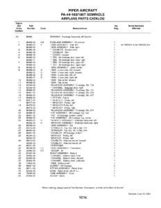
This Piper PA-31 Navajo parts catalog is the comprehensive reference for identifying and ordering replacement parts across the entire aircraft. Each section opens with an illustration showing every component in exploded view, followed by a detailed parts listing that includes figure and index number, part number, code, nomenclature, quantity required, and the exact serial number ranges the part applies to. This structure lets you trace a part from the illustration directly to its part number and confirm whether it fits your specific aircraft serial number.
The catalog covers all major systems: airframe structure including wings, fuselage, and tail surfaces; landing gear including struts, wheels, brakes, and steering; power plant including engines, propellers, exhaust, baffles, and cowling; fuel system including cells, lines, pumps, and valves; flight controls including aileron, rudder, elevator, and flap systems; hydraulic system including powerpaks, actuators, and lines; environmental systems including heaters, ventilation, and air conditioning; electrical system including harnesses, switches, circuit breakers, and lighting; and the complete electronics group covering radar, autopilots, and radio installations.
Because this catalog carries the February 1994 revision, it reflects the most current part numbers and supersessions available for the PA-31 series at that time. Each parts listing includes a serial number affected column that tells you exactly which aircraft the part fits, covering PA-31-300 serials 31-228 through 31-511, PA-31-310 serials from 31-5 onward, and PA-31-325 serials starting from 31-7400990. This level of detail is essential when ordering parts because the same assembly often used different components across different production blocks and model years.
Who This Manual Is For
This Piper parts catalog is written for aircraft mechanics, maintenance shops, parts managers, and owners who need to identify and order the correct replacement parts for PA-31 Navajo aircraft. If you maintain, repair, or restore a PA-31-300, PA-31-310, or PA-31-325, this catalog gives you the illustrated breakdowns and part numbers to get the right components the first time.
Get Your Piper PA-31 Parts Catalog Today
With over 1,000 pages of illustrated parts data, this catalog covers everything from wing spar attachments and fuselage bulkheads to propeller governors, hydraulic powerpaks, and autopilot installations. You get instant access to the complete parts breakdown for the PA-31 Navajo series, allowing you to identify parts, confirm serial number applicability, and place accurate orders without guesswork. The PDF format lets you search, zoom, and print any page, so you can bring the relevant section to the hangar or parts counter. Download it now and have the complete Piper PA-31 parts reference at your fingertips.
Reviews
There are no reviews yet.