
Piper PA-32RT Lance II Parts Catalog PA-32RT-300 PA-32RT-300T 1978-1979
Original price was: $39.95.$24.95Current price is: $24.95.
Complete Piper PA-32RT Lance II parts catalog covering PA-32RT-300 and PA-32RT-300T models from 1978-1979. Document 761 640, revised June 10, 2009. Exploded illustrations, part numbers, nomenclature, and serial number application for every major airframe and systems group.
Description
Piper PA-32RT Lance II Parts Catalog – PA-32RT-300 & PA-32RT-300T
This is the complete Piper parts catalog for the PA-32RT Lance II, covering both the normally aspirated PA-32RT-300 and the turbocharged PA-32RT-300T. Document number 761 640, revised June 10, 2009, this catalog is the reference for identifying and ordering replacement parts for these aircraft. It contains fourteen major sections spanning the entire airplane, from wing group through electronics, with exploded illustrations and detailed parts listings for every assembly.
File Details
- Manual Type: Parts Catalog
- Brand: Piper Aircraft Corporation
- Models Covered: PA-32RT-300, PA-32RT-300T (Lance II)
- Document Number: 761 640
- Revision Date: June 10, 2009
- Language: English
- File Format: PDF
Chapters Covered
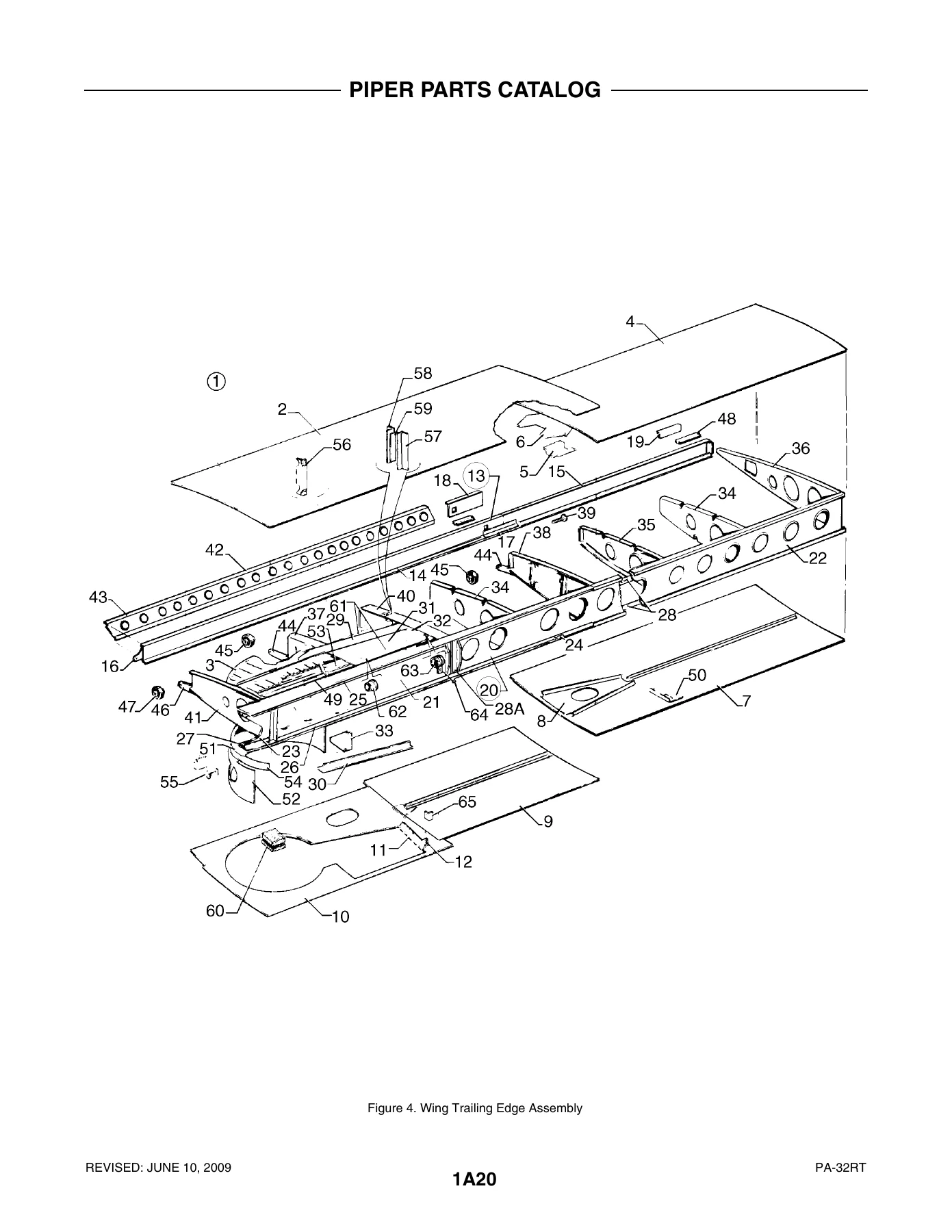
- Section I – Wing Group: Wing Installation, Wing Leading Edge Assembly, Wing Trailing Edge Assembly, Aileron Assembly, Flap Assembly
- Section II – Fuselage Group: Fuselage Assembly Complete, Upper Forward/Center/Aft Cockpit Assemblies, Lower Forward/Aft Cockpit Assemblies, Aft Section, Forward Cabin Door, Aft Cabin Door, Forward Baggage Door, Aft Cargo Door, Enclosure Installation
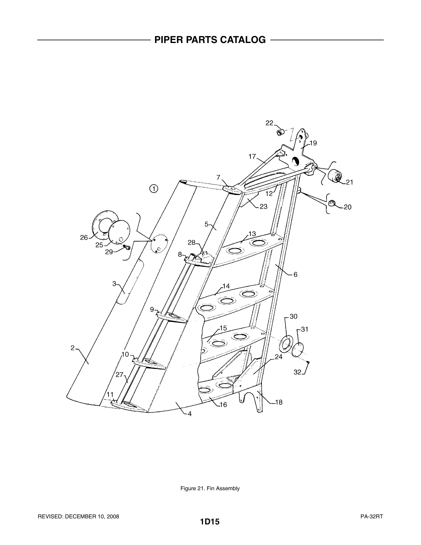
- Section III – Tail Surfaces Group: Tail Surfaces Installation, Stabilator Assembly, Fin Assembly, Rudder Assembly
- Section IV – Landing Gear Group: Nose Gear Installation, Nose Gear Assembly, Nose Wheel Assembly, Main Gear Installation, Main Gear Assembly, Main Wheel Assembly, Brake Assembly, Landing Gear Door Installation, Hand Brake Installation, Toe Brake Installation, Toe Brake Master Cylinder Assembly
- Section V – Cabin Equipment Group: Cockpit Finishing Installation, Window Curtain Installation, Carpet Installation, Headliner and Forward Air Duct Installation, Seats Installation, Vertically Adjustable Front Seat Assembly, 7th Seat Installation, Aft Facing Seat Assembly, Club Seating Installation
- Section VI – Instruments Group: Instrument Panel Installation, Vacuum System Installation, Pitot Static System Installation
- Section VII – Power Plant Group: Power Plant Installation (PA-32RT-300 and PA-32RT-300T), Engine Instrument Lines Installation, Engine Exhaust System Installation, Engine Baffle Installation, Engine Cowl Assembly, Propeller Assembly, Engine Controls Installation
- Section VIII – Fuel System Group: Forward Fuel System Installation, Aft Fuel System Installation, Fuel Tank Assemblies
- Section IX – Control System Group: Control System Installation, Flap Control Installation, Stabilator Trim Installation, Rudder Trim Mechanism Installation, Control Wheel Installation, Rudder Pedal Installation
- Section X – Hydraulic System Group: Hydraulic System Installation with Backup Landing Gear Extender
- Section XI – Environmental Group: Cabin Heat and Defroster System, Aft Fresh Air Duct Installation, Air Conditioning Compressor and Refrigerant Lines, Air Conditioning Duct and Evaporator Installation, Air Conditioning Condenser Installation, Oxygen System Installation
- Section XII – Electrical System Group: Electrical System Installation, Instrument Panel Electrical Installation, Air Conditioning Electrical Installation, Battery Box Installation, External Power Supply Installation, Standard Alternator Assembly (Chrysler), Air Conditioning Alternator Assembly (Prestolite)
- Section XIII – Electronics Group: Electric Trim Installation, AutoFlite II Installation, AutoControl III B Installation, AltiMatic III C Installation, King KFC-200 AutoPilot Installation, Piper Automatic Locator (ELT) Installation, Radar Altimeter Installation, Encoder Installation, Radio and Antenna System Installation, Audio Selector Assembly, Radar System Installation, Radio Installation Drawings
- Section XIV – Miscellaneous Group: Placards and Exterior Stencils, Optional Equipment Kits, Repair Kits
What This Piper Lance II Parts Catalog Delivers
Every parts listing in this catalog is organized by figure number and index number, with columns for part number, code, nomenclature, quantity required, and the specific aircraft serial numbers affected. The indentation system clearly distinguishes assemblies from components and sub-components, so you can see exactly what is included when you order a major assembly versus an individual part. Exploded illustrations accompany each section, showing how components fit together and making identification straightforward even for complex installations.
This catalog covers both the PA-32RT-300 and PA-32RT-300T, with serial number ranges that identify which parts apply to which production blocks. The 1978 PA-32RT-300 models span serial numbers 32R-7885002 through 32R-7885285, while 1979 models run from 32R-7985001 through 32R-7985106. For the turbocharged PA-32RT-300T, 1978 models cover 32R-7887002 through 32R-7887289, and 1979 models cover 32R-7987001 through 32R-7987126. Where parts differ between model years or between the 300 and 300T, code letters and serial number notes direct you to the correct component.
The power plant section is particularly detailed, covering the Lycoming IO-540-K1G5D engine installation for the PA-32RT-300 and the Lycoming TIO-540-S1AD for the PA-32RT-300T. Propeller assemblies, engine controls, exhaust systems, baffles, and cowl assemblies each have their own dedicated coverage. The fuel system section includes forward and aft fuel system installations, fuel tank assemblies, and the fuel selector valve installation, with separate breakdowns for normally aspirated and turbocharged configurations.
Landing gear coverage is extensive, with separate sections for nose gear and main gear, including wheel assemblies, brake assemblies, and landing gear door installations. The hydraulic system section covers the backup landing gear extender installation, with detailed parts breakdowns for the hydraulic pump, actuators, hoses, and tubing. For cabin equipment, you’ll find complete coverage of seats, carpet, headliner, window curtains, and interior finishing components, with color codes noted where applicable.
The electronics group covers the full range of avionics and autopilot installations available for these aircraft, including AutoFlite II, AutoControl III B, AltiMatic III C, and King KFC-200 systems. Radio installation drawings, antenna systems, static wicks, and audio selector assemblies are all documented. The miscellaneous group includes placards, exterior stencils, optional equipment kits, and repair kits, with references to applicable Piper Service Bulletins and Service Letters where relevant.
How This Catalog Helps You
Whether you are maintaining, repairing, or restoring a Piper PA-32RT Lance II, having the correct part number is essential. This catalog eliminates guesswork by providing the exact part numbers, nomenclature, and serial number applicability for every component on the aircraft. The exploded illustrations show assembly relationships, helping you understand how parts fit together before you order. The quantity required column ensures you order the right number of each item, and the code column alerts you to special usage conditions.
For shops and mechanics, this parts catalog is the reference for looking up replacement parts without relying on memory or generic aftermarket listings. For owners, it provides the information needed to communicate clearly with parts suppliers and to verify that the correct components are being installed. The serial number affected column is especially valuable for aircraft that fall within the production ranges covered, ensuring you get parts that are compatible with your specific airframe.
IMAGES PREVIEW
Instant PDF Delivery
This Piper PA-32RT Lance II parts catalog is delivered as an instant PDF download. No shipping, no waiting for a physical book to arrive. You can access it on any device—computer, tablet, or smartphone—and print the pages you need for the shop or hangar. The PDF format makes it easy to search, zoom in on detailed illustrations, and keep the entire catalog organized on your device. Whether you are ordering a single part or planning a major repair, this catalog gives you the reference you need, when you need it.
Reviews
There are no reviews yet.