
Piper PA-46-350P Malibu Mirage Airplane Parts Catalog 761-878 2007 – PDF Download
Original price was: $34.95.$19.95Current price is: $19.95.
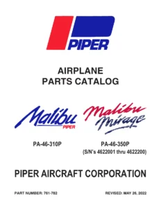
Complete illustrated Piper PA-46-350P Malibu Mirage Airplane Parts Catalog (Part No. 761-878, revised June 10, 2007) covering serial numbers 4636001 and up. Full exploded-view illustrations and part listings across all fourteen airframe and systems groups.
Description
Piper PA-46-350P Malibu Mirage Airplane Parts Catalog – Part Number 761-878
This is the complete Piper PA-46-350P Malibu Mirage Airplane Parts Catalog, published by Piper Aircraft, Inc. under document number 761-878, with the latest revision dated June 10, 2007. It applies to aircraft serial numbers 4636001 and up and is arranged as a two-card Aerofiche set that has been assembled into a single, page-by-page PDF for easy desktop and tablet use. Whether you are identifying a replacement skin, tracing a hydraulic tube assembly, sourcing a gear actuator, or confirming a fuel sender part number before ordering, this Piper PA-46-350P Malibu Mirage Airplane Parts Catalog is the document the parts counter and the maintenance shop work from.
File Details
- Manual type: Illustrated Airplane Parts Catalog (Aerofiche Card Set 1 & 2)
- Brand / Manufacturer: Piper Aircraft, Inc., Vero Beach, Florida
- Model: PA-46-350P Malibu Mirage
- Serial number coverage: 4636001 and up
- Document number: 761-878
- Reissued: December 10, 2006
- Latest revision in this file: June 10, 2007
- Language: English
- File format: PDF
- Page count: Approximately 500 pages
- Sections: Fourteen major sections plus a Numerical Index
- Illustrations: Exploded-view figures throughout every group
Chapters Covered
Every figure in this Piper PA-46-350P Malibu Mirage Airplane Parts Catalog is paired with a corresponding parts listing, and the catalog is divided into the fourteen major groups below, plus a Numerical Index at the back:
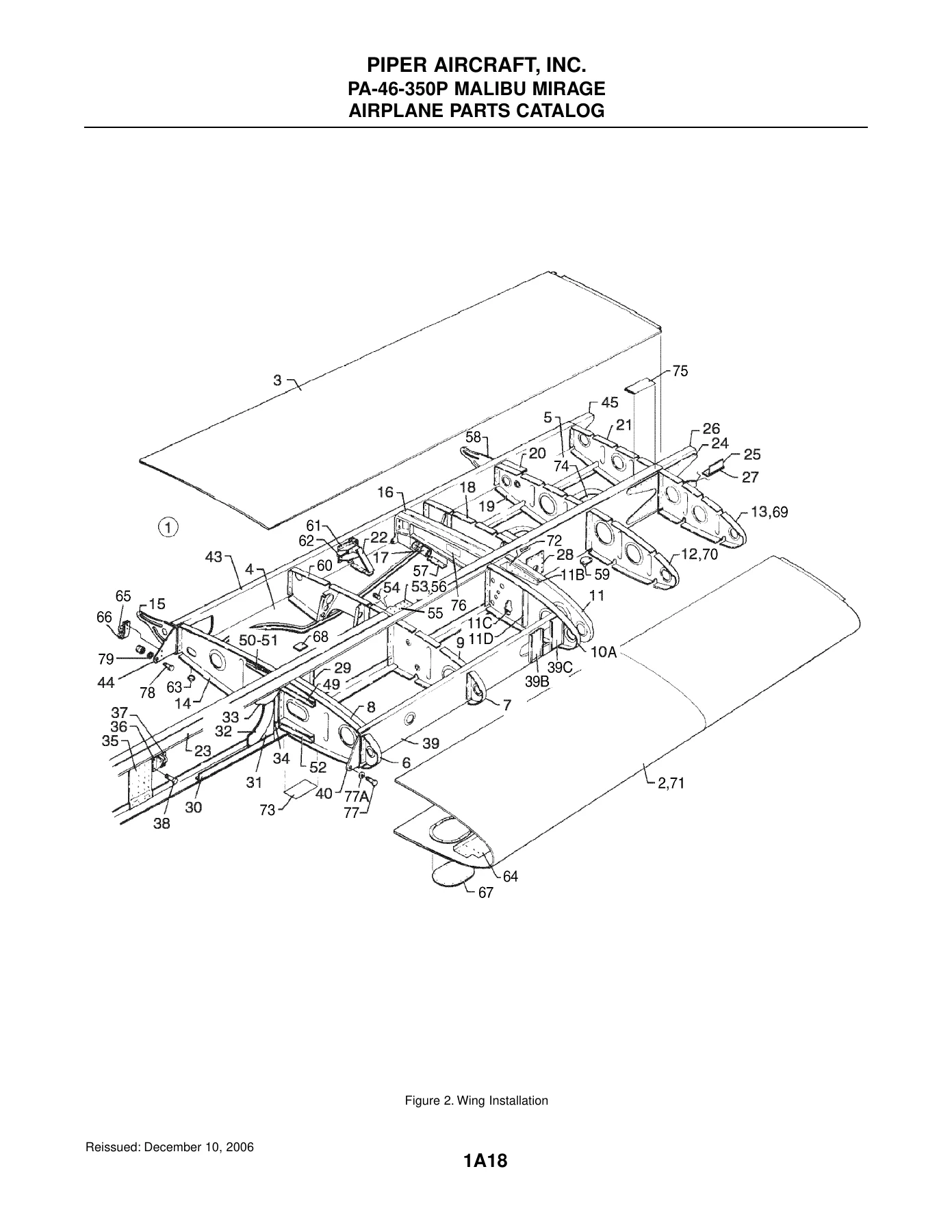
- Section I – Wing Group: Wing Installation; Wing to Fuselage Fairing Installation; Outboard Wing Installation; Aileron Assembly; Flap Installation
- Section II – Fuselage Group: Fuselage Assembly – Complete; Forward Baggage Compartment; Forward Cockpit; Center Cockpit; Aft Cabin; Rear Fuselage; Floorboard Installation; Cabin Entrance Door; Upper and Lower Cabin Entrance Door Assemblies; Emergency Door; Forward Baggage Door; Fuselage Enclosure
- Section III – Tail Surfaces Group: Tail Surfaces Installation; Fin Assembly; Rudder Assembly; Stabilator Assembly; Elevator Assembly
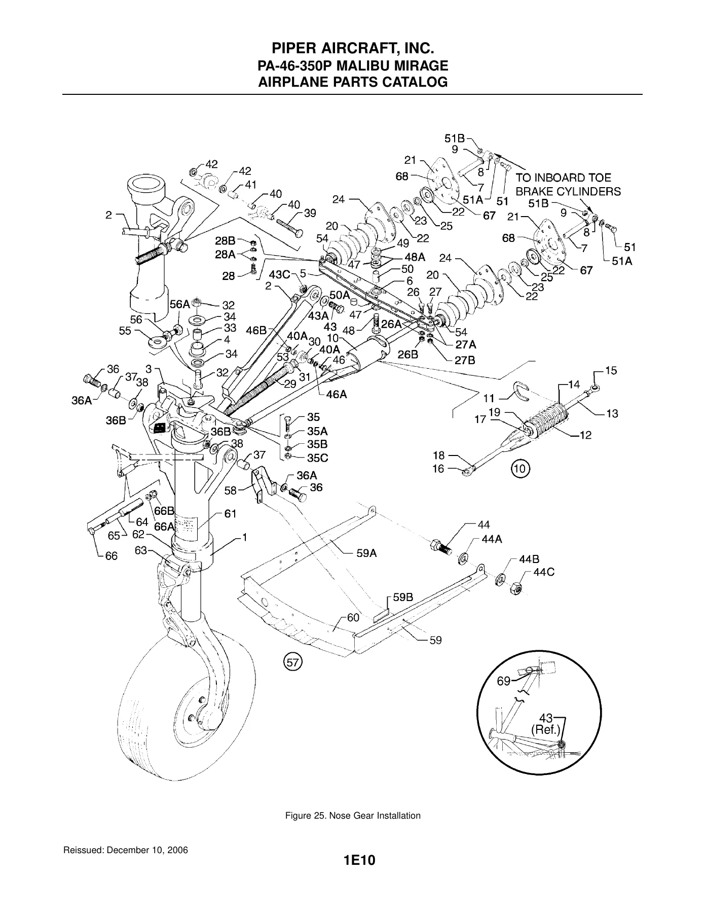
- Section IV – Landing Gear Group: Nose Gear Installation and Locking Actuator; Nose Gear and Nose Wheel Assemblies; Main Gear Installation and Locking Actuator; Main Gear Assembly; Main Wheel Assembly; Brake Assembly; Nose and Main Gear Door Actuation; Nose Gear Door Actuator; Brake System Installation; Toe Brake Installation
- Section V – Cabin Equipment Group: Cockpit Finishing; Side Panel Installation; Window Frame and Shade Installation; Sun Visor Installation (both early and later serial ranges); Cabin Carpet Installation; Seats Installation; Front Seat Assembly; Center Seat Assembly, Aft Facing; Aft Bench Seat Assembly; Relief Tube Installation
- Section VI – Instruments Group: Instrument Panel Installation (multiple serial ranges); Standby Instrument Installation; Instrument Panel Installation With Entegra; Vacuum System Installation; Pitot Static System Installation (standard, optional, and With Entegra)
- Section VII – Power Plant Group: Power Plant Installation; Engine Instrument Lines Installation; Engine Baffle Installation; Engine Cowl Installation; Engine Controls Installation
- Section VIII – Fuel System Group: Fuel System Installation; Fuel System Components
- Section IX – Control System Group: Control Console Installation; Quadrant Assembly; Aileron Control Installation; Rudder Control Installation; Aileron and Rudder Interconnect Installation; Elevator Control Installation; Elevator Trim Installation; Flap Drive (Electrical and Mechanical) Installation; Control Wheel Installation
- Section X – Hydraulic System Group: Forward Hydraulic System Installation; Sequence Valve; Center Hydraulic System Installation; Emergency Release Valve; Aft Hydraulic System Installation; Hydraulic Pump Assembly
- Section XI – Environmental Group: Cabin Air System Installation; Cabin Pressurization Control System Installation; Bleed Air and Conditioning System Installation; Bleed and Ram Air Selector Valve Assembly; Air Modulation Valve Assembly; Air Conditioning Compressor and Freon Lines Installation; Air Conditioning Evaporator and Condenser Installation; Pneumatic Deicing System Installation; Oxygen System Installation
- Section XII – Electrical System Group: Forward, Center, and Aft Electrical System Installations; Instrument Panel Electrical Installation (multiple serial ranges); Overhead Switch Panel Installation; Pilot and Copilot Circuit Breaker Panel Installations; Electrical Power Panel Assembly; Battery Installation; External Power Installation; Landing Light Installation; Navigation and Strobe Lights Installation; Propeller Heat System Installation; Precise Flight Speed Brake System
- Section XIII – Electronics Group: King KAP 150/KFC 150 Autopilot/Flight Director Installation; Antenna, Static Wicks and Stereo Installation (Without and With Entegra); Emergency Locator Transmitter Installation (Artex 110-4); Avionics Cooling Installation; Avionics Cooling – Blower Installation; Avionics Installation Drawings
- Section XIV – Miscellaneous Group: Placards and Decals Installation; Piper Service and Optional Kits; Special Tools; Miscellaneous Hardware and Consumables
- Numerical Index: Alphabetical-by-part-number lookup across every figure and item number in the catalog
What This Parts Catalog Gives You
Rather than a generic repair manual, this is the same illustrated parts catalog Piper Aircraft distributes to its service network for the PA-46-350P Malibu Mirage. Every replacement part is presented inside a figure with an item callout, then repeated in a parts listing with the part number, nomenclature, quantity required, and the exact serial number range the part applies to. That last column matters enormously on a Malibu Mirage, because Piper introduced running changes across the production run – from the early 1995 aircraft through the final 2007 and up serials – and the catalog breaks those changes out line by line. A fuel sender, cabin door latch, gear actuator, or wing skin that fits one serial block may not fit another, and this catalog shows you exactly which part number belongs to your airplane.
Indentation in the nomenclature column also tells you how parts nest. Items with an asterisk sit under the next higher assembly; ordering the assembly brings the indented items with it. That single convention saves hours of guesswork when you are rebuilding a flap, a stabilator, or a seat frame and need to know whether a bracket is a separate line item or part of the assembly you are already buying.
Why Technicians and Owners Keep This Catalog on Hand
When an airplane has been in service for over a decade, part numbers drift, supersessions accumulate, and vendors drop components. Having the illustrated catalog in front of you lets you match what is physically on the aircraft to what the factory called it, cross a callout number on a figure to the exact part number in the listing, and confirm the serial-number effectivity before the order is placed. It is the difference between ordering the right $40 bracket the first time and returning three wrong ones. The catalog also covers options many aircraft carry – air conditioning, oxygen, deicing, speed brakes, Entegra-equipped panels, GPS antennas, and specific avionics installations – so you are not left guessing on the optional systems either.
The exploded views are equally useful for reassembly. Exploded diagrams show washer stacks, bushing locations, bolt direction, and how hardware plates and doublers fit between skins and ribs. Hydraulic tubing runs, pitot-static routing, freon lines, and electrical harness paths are drawn out in the same style, so you can trace a line end to end without crawling blindly through the airframe.
IMAGES PREVIEW
Instant PDF Delivery – No Shipping, No Waiting
Your purchase gives you an instant download of this Piper PA-46-350P Malibu Mirage Airplane Parts Catalog as a PDF file. There is no physical shipment, no waiting period, and no risk of a damaged package. Open it on a desktop computer in the shop, on a laptop or tablet at the aircraft, or on a phone for a quick part-number check on the ramp. Pages can be printed for a specific job – a wing figure, a gear exploded view, a placard layout – without dragging the whole catalog into the hangar. Because the file is a single continuous PDF, you can page through from the front cover through every section to the Numerical Index at the back, matching the original Aerofiche card sequence exactly.
If you maintain, repair, restore, or simply own a PA-46-350P Malibu Mirage, this parts catalog is a working reference you will return to every time a component needs identification, replacement, or reassembly. Order the download today and have the complete illustrated catalog in your hands in minutes.
Reviews
There are no reviews yet.