★ TRUSTED BY 321,897+ PROFESSIONALS WORLDWIDE
🏢
Trusted Business
Verified & Licensed
🛡️
Virus Free Files
100% Safe Downloads
🔒
Secure Payment
SSL Protected
Instant Delivery
Available Immediately
Sale!

Piper Seneca III/IV PA-34-220T Illustrated Parts Catalog PDF (761 750)

Original price was: $34.95.Current price is: $19.95.

Complete 577-page Piper PA-34-220T Seneca III & Seneca IV Illustrated Parts Catalog with exploded diagrams, part numbers, and full serial-number effectivity for every airframe system. Instant PDF download.

SKU: HD-IPC-PA34-220T-SENECA-761750 Category: Tags: , , , Vendor: Forklift Manuals
Instant PDF Download
Available immediately
💾
Save to Your Device
Download & keep forever
🛡️
Antivirus Scanned
100% virus-free
🌍
Trusted Worldwide
175,000+ customers

Description

Piper Seneca III/IV PA-34-220T Illustrated Parts Catalog

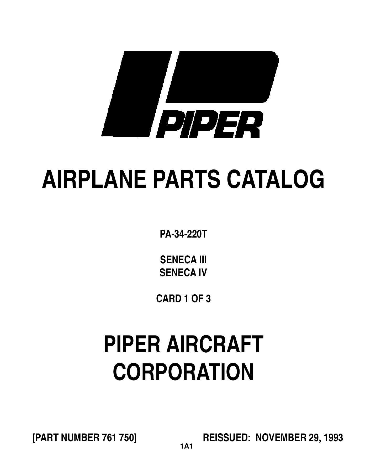
This is the complete, 577-page Piper Aircraft Illustrated Parts Catalog (document number 761 750) covering the PA-34-220T Seneca III and Seneca IV, reissued November 29, 1993 and current through the November 1993 revision. Originally distributed on Aerofiche microfilm cards, every card and grid location has been reproduced here as a searchable PDF, so the Piper Seneca III/IV PA-34-220T Illustrated Parts Catalog you download is a full, page-for-page match of the factory set.

File Details

  • Manual type: Illustrated (Airplane) Parts Catalog
  • Aircraft: Piper PA-34-220T Seneca III (14 Volt and 28 Volt) and Seneca IV
  • Document/Part Number: 761 750
  • Reissued: November 29, 1993 (Revision CR 931129)
  • Language: English
  • Page count: 577 pages
  • File format: PDF, instant download

Complete PDF Bookmark Tree

Complete Bookmarks

The complete bookmarks in the “Piper Seneca III/IV PA-34-220T Illustrated Parts Catalog PDF (761 750)” are as follows:

761-750 – SENECA III/IV PARTS CATALOG – PA-34-220Tp. 1
INTRODUCTIONp. 4
TABLE OF CONTENTSp. 9
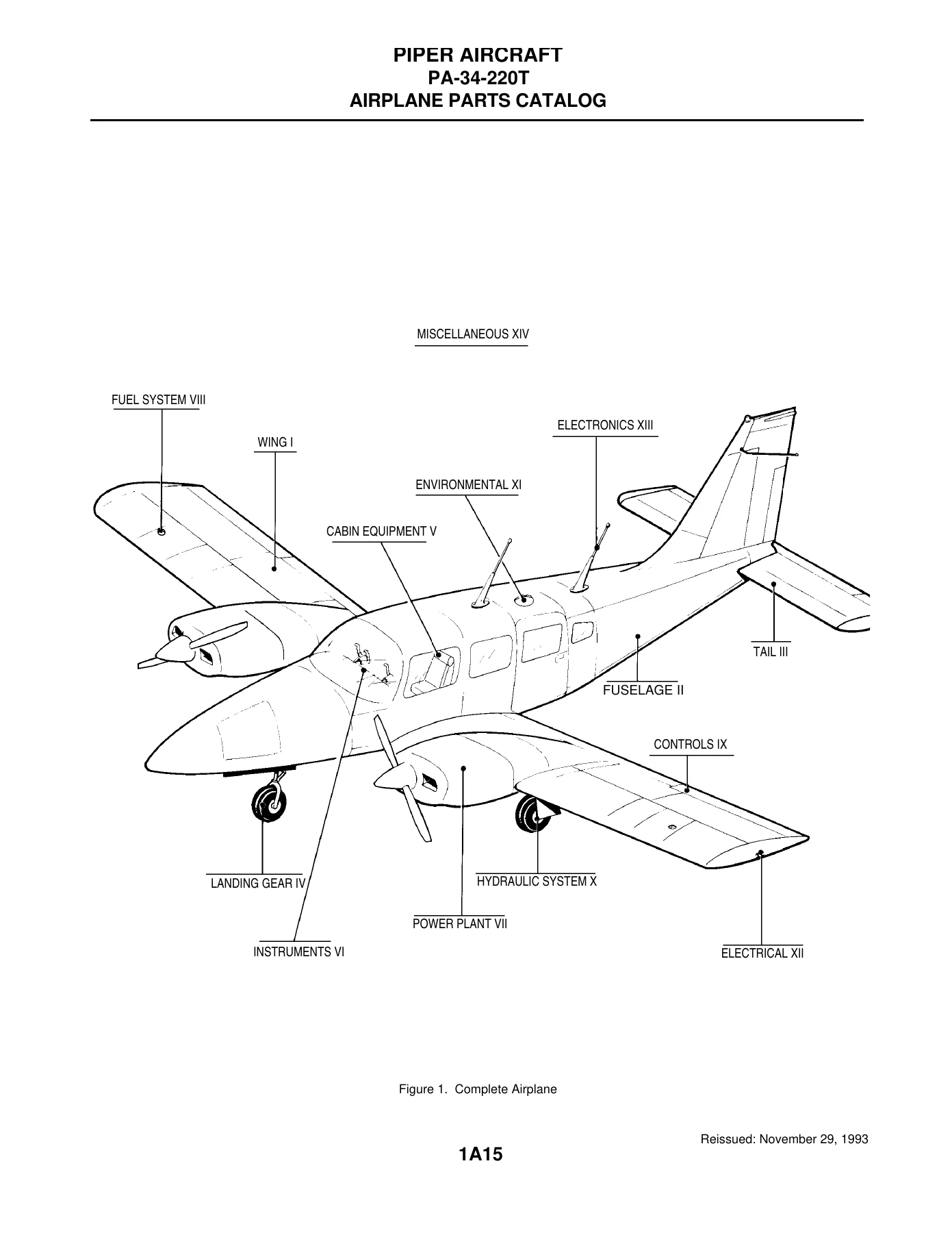
FIGURE 1. COMPLETE AIRPLANEp. 15
SECTION I – WING GROUPp. 17
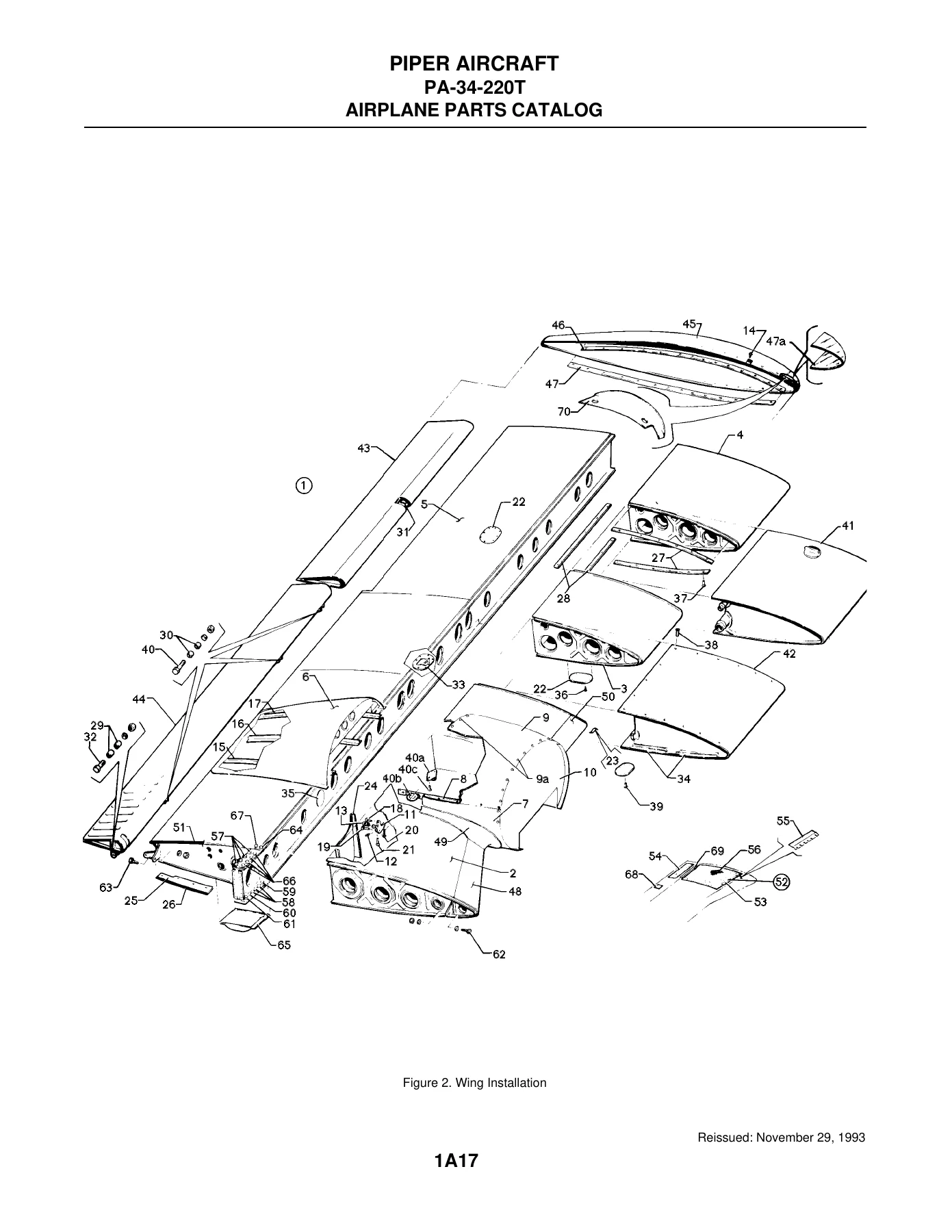
FIGURE 2. WING INSTALLATIONp. 17
FIGURE 3. WING LEADING EDGE ASSEMBLYp. 22
FIGURE 4. WING TRAILING EDGE ASSEMBLYp. 29
FIGURE 5. AILERON ASSEMBLYp. 34
FIGURE 6. FLAP ASSEMBLYp. 37
SECTION II – FUSELAGE GROUPp. 41
FIGURE 7. FUSELAGE ASSEMBLY – COMPLETEp. 41
FIGURE 8. FUSELAGE NOSE CONE ASSEMBLYp. 44
FIGURE 9. FUSELAGE UPPER FORWARD COCKPIT ASSEMBLYp. 47
FIGURE 10. FUSELAGE UPPER CENTER COCKPIT ASSEMBLYp. 54
FIGURE 11. FUSELAGE UPPER AFT COCKPIT ASSEMBLYp. 58
FIGURE 12. FUSELAGE LOWER FORWARD COCKPIT ASSEMBLYp. 61
FIGURE 13. FUSELAGE LOWER AFT COCKPIT ASSEMBLYp. 65
FIGURE 14. FUSELAGE AFT SECTIONp. 69
FIGURE 15. FUSELAGE FORWARD CABIN DOORp. 73
FIGURE 16. FUSELAGE AFT CABIN DOORp. 78
FIGURE 17. FUSELAGE AFT CARGO DOORp. 84
FIGURE 18. FUSELAGE FORWARD BAGGAGE DOOR ASSEMBLYp. 89
FIGURE 19. FUSELAGE ENCLOSURE INSTALLATIONp. 92
SECTION III – TAIL SURFACES GROUPp. 97
FIGURE 20. TAIL SURFACES INSTALLATIONp. 97
FIGURE 21. STABILATOR ASSEMBLYp. 101
FIGURE 22. FIN ASSEMBLYp. 105
FIGURE 23. RUDDER ASSEMBLYp. 108
SECTION IV – LANDING GEAR GROUPp. 111
FIGURE 24. NOSE GEAR INSTALLATIONp. 111
FIGURE 25. NOSE GEAR ASSEMBLYp. 115
FIGURE 26. NOSE WHEEL ASSEMBLY (CLEVELAND)p. 119
FIGURE 26A. NOSE WHEEL ASSEMBLY (MCCAULEY)p. 122
FIGURE 27. MAIN GEAR INSTALLATIONp. 125
FIGURE 28. MAIN GEAR ASSEMBLYp. 129
FIGURE 29. MAIN WHEEL ASSEMBLY (CLEVELAND)p. 133
FIGURE 30. BRAKE ASSEMBLYp. 136
FIGURE 31. NOSE AND MAIN GEAR DOOR ACTUATION INSTALLATIONSp. 139
FIGURE 32. BRAKE SYSTEM INSTALLATIONp. 143
FIGURE 33. TOE BRAKE INSTALLATIONp. 146
FIGURE 34. TOE BRAKE MASTER CYLINDER ASSEMBLYp. 149
SECTION V – CABIN EQUIPMENT GROUPp. 153
FIGURE 35. FORWARD BAGGAGE COMPARTMENT FINISHING INSTALLATIONp. 153
FIGURE 36. COCKPIT FINISHING INSTALLATIONp. 156
FIGURE 36A. COCKPIT FINISHING INSTALLATION (SERIAL NUMBERS 3448038 AND UP)p. 162
FIGURE 37. WINDOW CURTAINS INSTALLATIONp. 165
FIGURE 37A. WINDOW SHADES AND REVEALS INSTALLATION (SERIAL NUMBERS 3448038 AND UP)p. 168
FIGURE 38. CARPET INSTALLATIONp. 171
FIGURE 39. FORWARD FRESH AIR DUCT AND HEADLINER INSTALLATIONp. 177
FIGURE 39A. FORWARD FRESH AIR DUCT AND HEADLINER INSTALLATION (SERIAL NUMBERS 3448038 AND UP)p. 180
FIGURE 40. SEATS INSTALLATIONp. 186
FIGURE 41. VERTICALLY ADJUSTABLE FRONT SEAT ASSEMBLYp. 192
FIGURE 42. 7TH SEAT INSTALLATIONp. 197
FIGURE 43. AFT FACING SEAT ASSEMBLY – CENTERp. 200
FIGURE 44. CLUB SEATING INSTALLATIONp. 203
SECTION VI – INSTRUMENT GROUPp. 209
FIGURE 45. INSTRUMENT PANEL INSTALLATIONp. 209
FIGURE 45A. INSTRUMENT PANEL INSTALLATION (28 VOLT SYSTEM, INCLUDES SERIAL NUMBERS 3448001 THRU 3448037)p. 213
FIGURE 45B. INSTRUMENT PANEL INSTALLATION (SERIAL NUMBERS 3448038 AND UP)p. 217
FIGURE 46. GYRO VACUUM SYSTEM INSTALLATIONp. 221
FIGURE 47. PITOT STATIC SYSTEM INSTALLATIONp. 224
SECTION VII – POWER PLANT GROUPp. 229
FIGURE 48. POWER PLANT INSTALLATIONp. 229
FIGURE 49. ENGINE INSTRUMENT LINES INSTALLATIONp. 233
FIGURE 50. ENGINE BAFFLE INSTALLATIONp. 237
FIGURE 51. ENGINE COWLING ASSEMBLYp. 242
FIGURE 52. COWL FLAP INSTALLATIONp. 245
FIGURE 53. TWO BLADE PROPELLER ASSEMBLY (HARTZELL)p. 248
FIGURE 54. THREE BLADE PROPELLER ASSEMBLY (MCCAULEY)p. 251
FIGURE 55. PROPELLER SYNCHROPHASER SYSTEM INSTALLATION (S/N 34-8133002 THRU 34-8133195)p. 255
FIGURE 55A. PROPELLER SYNCHROPHASER SYSTEM INSTALLATION (S/N 34-8133001, 34-8133196 AND UP, 3448001 AND UP)p. 258
FIGURE 55B. PROPELLER UNFEATHERING SYSTEM INSTALLATION (S/N 34-8333001 AND UP, 3448001 AND UP)p. 261
FIGURE 56. ENGINE CONTROLS INSTALLATIONp. 266
FIGURE 57. QUADRANT ASSEMBLYp. 270
FIGURE 58. NACELLE INSTALLATIONp. 273
SECTION VIII – FUEL SYSTEM GROUPp. 293
FIGURE 59. FUEL SYSTEM INSTALLATION – WING AND FUSELAGEp. 293
FIGURE 60. FUEL SYSTEM INSTALLATION – ENGINEp. 297
FIGURE 61. FUEL TANK ASSEMBLIESp. 300
SECTION IX – CONTROL SYSTEM GROUPp. 305
FIGURE 62. AILERON CONTROL INSTALLATIONp. 305
FIGURE 63. RUDDER CONTROL INSTALLATIONp. 309
FIGURE 64. RUDDER TRIM INSTALLATIONp. 312
FIGURE 65. STABILATOR CONTROL INSTALLATIONp. 318
FIGURE 66. STABILATOR TRIM INSTALLATIONp. 321
FIGURE 67. FLAP CONTROL INSTALLATION (S/N 34-8133001 THRU 34-8433086)p. 325
FIGURE 67A. FLAP CONTROL INSTALLATION (S/N 34-8533001 AND UP, 3448001 AND UP)p. 329
FIGURE 68. CONTROL WHEEL INSTALLATIONp. 333
FIGURE 69. BOBWEIGHT INSTALLATIONp. 337
FIGURE 70. RUDDER PEDAL INSTALLATIONp. 342
SECTION X – HYDRAULIC SYSTEM GROUPp. 347
FIGURE 71. HYDRAULIC SYSTEM INSTALLATIONp. 347
SECTION XI – ENVIRONMENTAL GROUPp. 353
FIGURE 72. HEAT AND DEFROST SYSTEM INSTALLATIONp. 353
FIGURE 73. JANITROL HEATER ASSEMBLYp. 356
FIGURE 74. JANITROL HEATER COMPONENTSp. 359
FIGURE 75. HEATER DUCT INSTALLATIONp. 362
FIGURE 76. HEATER FUEL SYSTEM INSTALLATIONp. 365
FIGURE 77. HEATER CONTROLS INSTALLATIONp. 370
FIGURE 78. AFT FRESH AIR DUCT INSTALLATIONp. 373
FIGURE 79. AIR CONDITIONING COMPRESSOR AND REFRIGERANT LINES INSTALLATIONp. 376
FIGURE 80. AIR CONDITIONING DUCT AND EVAPORATOR INSTALLATIONp. 379
FIGURE 81. AIR CONDITIONING CONDENSER AND SCOOP INSTALLATION (14 VOLT SYSTEM)p. 382
FIGURE 81A. AIR CONDITIONING CONDENSER AND SCOOP INSTALLATION (28 VOLT SYSTEM)p. 386
FIGURE 82. OXYGEN SYSTEM INSTALLATION (FIXED)p. 389
FIGURE 82A. OXYGEN SYSTEM INSTALLATIONp. 396
FIGURE 83. PNEUMATIC DEICER INSTALLATION (14 VOLT SYSTEM)p. 399
FIGURE 83A. PNEUMATIC DEICER INSTALLATION (28 VOLT SYSTEM)p. 403
SECTION XII – ELECTRICAL SYSTEM GROUPp. 407
FIGURE 84. ELECTRICAL SYSTEM INSTALLATION (14 VOLT SYSTEM)p. 407
FIGURE 84A. ELECTRICAL SYSTEM INSTALLATION (28 VOLT SYSTEM)p. 411
FIGURE 85. INSTRUMENT PANEL ELECTRICAL INSTALLATION (14 VOLT SYSTEM)p. 415
FIGURE 85A. INSTRUMENT PANEL ELECTRICAL INSTALLATION (28 VOLT SYSTEM)p. 422
FIGURE 85B. CIRCUIT BREAKER PANEL ASSEMBLY (28 VOLT SYSTEM)p. 426
FIGURE 85C. ELECTRICAL/AVIONICS SWITCHES (SERIAL NUMBERS 3448038 AND UP)p. 429
FIGURE 85D. ICE PROTECTION SYSTEM CONTROLS (SERIAL NUMBERS 3448038 AND UP)p. 432
FIGURE 86. AIR CONDITIONING ELECTRICAL INSTALLATIONp. 435
FIGURE 87. EXTERNAL POWER SUPPLY INSTALLATION (14 VOLT SYSTEM)p. 438
FIGURE 87A. EXTERNAL POWER SUPPLY INSTALLATION (28 VOLT SYSTEM)p. 441
FIGURE 87B. BATTERY INSTALLATION (28 VOLT SYSTEM)p. 444
FIGURE 88. STROBE LIGHTS INSTALLATION (14 VOLT SYSTEM)p. 447
FIGURE 88A. STROBE LIGHTS INSTALLATION (28 VOLT SYSTEM)p. 453
FIGURE 89. LANDING LIGHT INSTALLATIONp. 456
FIGURE 90. TWO BLADE PROPELLER ELECTRIC DEICER INSTALLATIONp. 459
FIGURE 91. THREE BLADE PROPELLER ELECTRIC DEICER INSTALLATIONp. 462
FIGURE 92. HEATED GLASS PANEL INSTALLATIONp. 465
SECTION XIII – ELECTRONICS GROUPp. 469
FIGURE 93. CENTURY 21 AUTOPILOT INSTALLATIONp. 469
FIGURE 93A. CENTURY 41 AUTOPILOT INSTALLATION (S/N 34-8133010 AND UP)p. 472
FIGURE 93B. CENTURY 31 AUTOPILOT INSTALLATION (S/N 34-8433001 AND UP)p. 475
FIGURE 93C. KING KFC-200 AUTOPILOT/FLIGHT DIRECTOR INSTALLATIONp. 478
FIGURE 93D. KING KAP 150/KFC 150 AUTOPILOT/FLIGHT DIRECTOR INSTALLATION (S/N 34-8433001 AND UP)p. 481
FIGURE 94. PIPER AUTOMATIC LOCATOR (ELT 10) INSTALLATION (NARCO AVIONICS)p. 484
FIGURE 94A. PIPER AUTOMATIC LOCATOR (ELT 910) INSTALLATION (NARCO AVIONICS)p. 487
FIGURE 95. RADAR ALTIMETER INSTALLATION (BONZER)p. 490
FIGURE 96. RADAR ALTIMETER INSTALLATION (KING)p. 493
FIGURE 97. ENCODER INSTALLATION (NARCO AR 850)p. 496
FIGURE 98. RADIO ANTENNA SYSTEM AND STATIC WICKS INSTALLATIONp. 499
FIGURE 99. RADAR SYSTEM INSTALLATION (RCA WEATHERSCOUT II, BENDIX RDR-160 AND RDS-82, AND KING KWX-56)p. 502
FIGURE 99A. ELECTRIC PITCH TRIM INSTALLATION (S/N 34-8433050 AND UP)p. 505
FIGURE 100. AVIONICS COOLING INSTALLATION (TYPICAL)p. 508
SECTION XIV – MISCELLANEOUS GROUPp. 513
FIGURE 101. PLACARDS AND EXTERIOR STENCILSp. 513
OPTIONAL EQUIPMENT KITS, REPAIR KITS, SPECIAL TOOLS AND MISCELLANEOUS HARDWAREp. 521
CONSUMABLESp. 522
AVIONICS INSTALLATIONSp. 524
NUMERICAL INDEXp. 542

Serial Numbers Covered

This parts catalog applies to Seneca III and Seneca IV airframes in the following serial number ranges: 34-8133001 thru 34-8133277, 34-8233001 thru 34-8233205, 34-8333001 thru 34-8333129, 34-8433001 thru 34-8433088, 34-8533001 thru 34-8533069, 34-8633001 thru 34-8633031, 3433001 and up, and 3448005 and up. Many individual figures inside the catalog are further broken down by specific serial-number effectivity (for example, instrument panel and cockpit finishing variations at s/n 3448038 and up), so you can match parts precisely to your airplane.

Chapters Covered

  • Section I – Wing Group (wing, leading/trailing edge, aileron, flap)
  • Section II – Fuselage Group (complete fuselage, nose cone, forward/center/aft cockpit, cabin doors)
  • Section III – Tail Surfaces Group (stabilator, fin, rudder)
  • Section IV – Landing Gear Group (nose gear, main gear, wheels, brakes)
  • Section V – Cabin Equipment Group (baggage compartment, seats, carpet, headliner)
  • Section VI – Instruments Group (14V and 28V instrument panels, gyro vacuum, pitot static)
  • Section VII – Power Plant Group (engine installation, cowl, propellers, controls, nacelle)
  • Section VIII – Fuel System Group (wing/fuselage fuel system, engine fuel system, fuel tanks)
  • Section IX – Control System Group (aileron, rudder, stabilator, flap, control wheel controls)
  • Section X – Hydraulic System Group
  • Section XI – Environmental Group (heat/defrost, air conditioning, oxygen, pneumatic deicer)
  • Section XII – Electrical System Group (14V/28V electrical, circuit breakers, external power, battery, strobe and landing lights)
  • Section XIII – Electronics Group (autopilots, ELT, radar altimeter, encoder, antenna and radar systems)
  • Section XIV – Miscellaneous Group (placards/stencils, optional equipment kits, repair kits, special tools, consumables)

IMAGES PREVIEW

Piper Seneca III/IV PA-34-220T Illustrated Parts Catalog PDF (761 750) — PDF page 15 preview
Piper Seneca III/IV PA-34-220T Illustrated Parts Catalog PDF (761 750) — PDF page 17 preview
Piper Seneca III/IV PA-34-220T Illustrated Parts Catalog PDF (761 750) — PDF page 1 preview

Together these fourteen sections take a technician through the complete PA-34-220T airframe, giving figure-by-figure exploded illustrations paired with parts lists that show part number, code, nomenclature, quantity required, and serial-number effectivity for essentially every replaceable component on the Seneca III and Seneca IV.

Why You Need the Piper Seneca III/IV PA-34-220T Illustrated Parts Catalog

Ordering the wrong part number on a Seneca III/IV costs time and money, especially on an airframe with this many mid-production running changes. This Illustrated Parts Catalog lets you positively identify every part by its figure and index number before you order, confirm which serial-number range it applies to, and cross-check optional equipment kits and special tools called out for specific systems. Whether you’re sourcing a wing skin, a brake assembly, an autopilot bracket, or cabin trim, this catalog is the reference that keeps your Seneca III/IV parts orders accurate the first time.

This is an instant PDF download – there’s no shipping, no waiting, and no physical Aerofiche reader required. Read the Piper Seneca III/IV PA-34-220T Illustrated Parts Catalog on a laptop, tablet, or phone in the hangar, or print any page you need at the bench.
Reviews

There are no reviews yet.

Be the first to review “Piper Seneca III/IV PA-34-220T Illustrated Parts Catalog PDF (761 750)”

What Our Customers Say

★★★★★ Live reviews from customers
Loading customer reviews...
0
    0
    Your Cart
    Your cart is emptyReturn to Shop
    🛒
    Recently Purchased
    🕒 verified order