
Raymond 9600 & 9700 Swing-Reach Lift Truck Maintenance Manual – PDF
Original price was: $39.95.$24.95Current price is: $24.95.
Complete 475-page Raymond maintenance manual for 9600 and 9700 Swing-Reach lift trucks. Covers scheduled maintenance, electrical and hydraulic troubleshooting, fault codes, component procedures, wire guidance, and theory of operation. Publication 1089040E, 2023 edition.
Description
Raymond 9600 & 9700 Swing-Reach Lift Truck Maintenance Manual
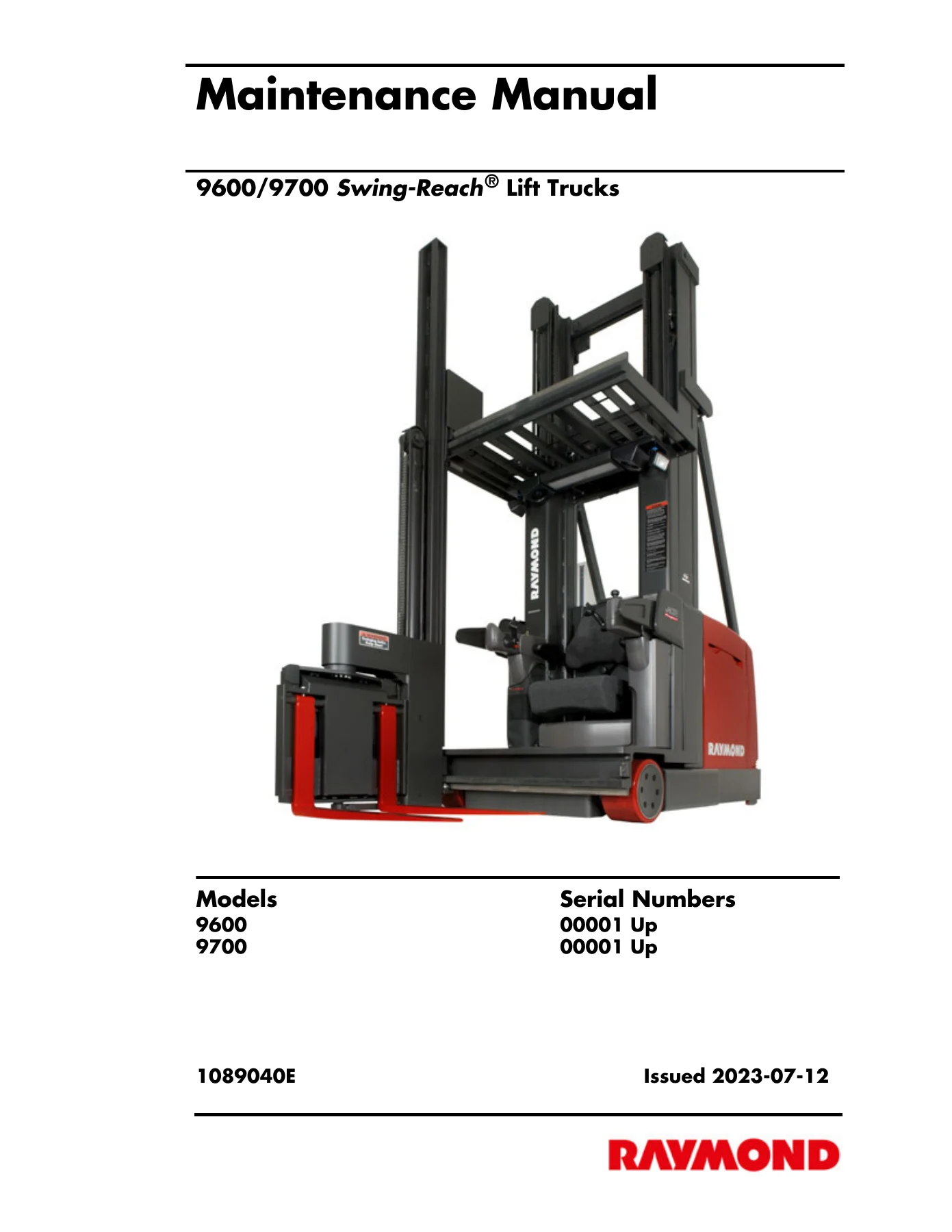
This is the complete maintenance manual for Raymond 9600 and 9700 Swing-Reach lift trucks, serial numbers 00001 and up. Publication 1089040E, issued July 2023, at 475 pages. It is the reference document for scheduled maintenance, troubleshooting, component repair, and system theory on both models. Everything inside applies directly to the 9600 and 9700 as built, with procedures written around the actual assemblies and wiring found on these trucks.
File Details
- Manual type: Maintenance Manual
- Brand: Raymond
- Models covered: 9600, 9700 Swing-Reach Lift Trucks
- Serial numbers: 00001 and Up (both models)
- Publication number: 1089040E
- Revision: E (2023-07-12)
- Language: English
- Page count: 475
- File format: PDF
Chapters Covered
- How to Use This Manual — manual design, abbreviations and symbols, Interactive Electronic Technical Manuals
- Safety — definitions, general safety, battery safety, static precautions, jacking safety, blocking and lifting safety, welding safety
- Systems Overview — introduction, lift truck specifications, general information, truck installation, FlashWare, operator displays, modes of operation
- Scheduled Maintenance — maintenance guidelines, Maintenance Minder Tool, initial 90 day/250 HD service, every 180 days or 500 HD, every 360 days or 2000 HD, lubrication points, chain maintenance, fork inspection
- Troubleshooting — electrical troubleshooting, communication error codes (5x series), wire guidance troubleshooting, steering fault codes (G series), hydraulic troubleshooting guidelines, hydraulic symptom tables, travel problem symptom tables, electrical problem symptom tables
- Messages, Codes, and Tests — messages and codes summary, individual fault codes with causes and corrections, analog tests, input tests, output tests
- Component Procedures — special tools, decals, steering and controls, drive and brake, electrical components, motors, hydraulic components, mast, chain, hose, cable, mini-mast and load handler
- Theory of Operation — system architecture, functional operation, hydraulic components, pinout matrix
- Appendix — lubrication specification chart, adhesives and sealants, component specific service/torque chart, torque charts (hydraulic fittings, face seal O-rings, standard ferrous, metric ferrous, brass, thread-forming screws), decimal equivalents, standard/metric conversions
- Index — alphabetical subject listing with page references
- Schematics — electrical schematic (6 sheets), hydraulic schematic (2 sheets)
What This Raymond 9600 & 9700 Manual Gives You
This is a full workshop-level document, not a condensed owner’s guide. The electrical troubleshooting section walks through the 5x-series communication error codes one at a time, including Code 51, Code 55, Code 56, Code 57, Code 59, Code 5A, Code 5E, Code 5G, and Code 5J. Each entry explains what the code means, which tests to run, and what to check when the code is intermittent. The steering fault code section covers the G-series codes (G2, G3, G4, G5, G7, GD, GE) with specific diagnosis paths depending on whether the code appears before or during operation.
The messages and codes chapter is effectively a fault-code dictionary for the whole truck. It lists every operator message and code the 9600/9700 can produce — from Battery Low, No Lift and Check Battery Gates to Code 1H (TPA out-of-range), Code 2A through 2X (traction motor and TPA faults), Code 42 through 4K (contactor faults), Code 50 through 5Q (CAN communication faults), Code 64 through 6F (mast height and lift faults), Code 7E through 7X (LPA faults), Code 80 through 8X (pot and brake faults), Code 91 through 9M (wire guidance faults), Code A0 through AX (software and memory faults), and Code B0 through X6. Each code entry lists the reason, the tests to run, and the corrective action.
The test section is where the manual earns its place on the service cart. Analog tests include throttle pot (VR1), lift/lower pot (VR2), traction motor temperature, lift motor temperature, TPA temperature, traction motor current, CM +12VDC supply, main lift pressure sensor, TM +12VDC supply, battery voltage, lift pendant, lower pendant, LPA temperature, lift motor current, travel request, lift/lower request, +5VDC pot supply, brake sense, steer motor current, mini power supply, CM EPO sense, TM EPO sense, load handler motor temperature, traverse/reach pot (VR4), traverse position feedback pot (VR5), rotate command pot (VR3), rotate position feedback pot (VR6), mini-mast pressure sensor, TM B+Key, CM B+Key, traverse solenoid (SOL7) current, rotate solenoid (SOL8) current, BSM current, BSM voltage, BSM temperature, H2O sense, BSM communication, and Guidance Manager 12V power supply. Input tests cover carriage deadman switch (S23), lift reference prox (S11), lift/lower inhibit bypass switch (S7), FU1 sense, horn switch (S3), traction motor RPM, lift motor RPM, CAN communication, home steer proximity sensor, steer motor encoder, main lift height encoder, brake deadman switch (S2), steering encoder connect detect, steering encoder channels E1 and E2, neutral pulses, slack chain switches (S50 and S51), rail guidance switch (S15), auto/manual switch (S4), sidegate switches (S60 and S61), battery gate switches (S57 and S58), end-of-aisle sensors, load handler deadman (S9), reach proximity sensor, mini-mast height count and prox channels, lift select (S6), attachment (S5), in-aisle status, FU4 sense, custom inputs, and alternate end-of-aisle sensors. Output tests cover traction power contactor, steer power contactor, lift power contactor, load handler contactor, reach select solenoid (SOL11), lower solenoid (SOL1), horn, display interface card horn, travel alarm, fans, lift motor ramp, traction motor ramp, brake, relay toggle, display cycle, mini load hold (SOL5), steer motor, mini lift select (SOL6), main load hold (SOL3), main lift select (SOL4), reach/rotate direction A and B (SOL10A and SOL10B), reach/rotate PWM (SOL8), traverse direction A and B (SOL9A and SOL9B), traverse PWM (SOL7), supplemental display, custom outputs, lower solenoid check, and mini power supply.
Scheduled maintenance is broken out by interval: initial 90 day/250 deadman hour service, every 180 days or 500 HD, and every 360 days or 2000 HD. Components covered include the drive unit, hydraulic reservoir, power amplifiers, battery, brakes, contactors, control handles, deadman pedals, drain holes, electrical cables, fans, motors, overhead guard, pump coupling, safety belt or harness and tether, shorts to frame, side gates and barrier, stability pads, static straps, steering, switches, travel alarms, ventilation slots, warning decals, warning lights, wheels and tires, and wire guidance. Fork inspection is covered in detail with blade and shank straightness, fork angle, tip height, positioning locks, blade and shank wear, fork hooks, and markings. Chain maintenance includes elongation measurement, condition-cause chart, and adjustment procedures.
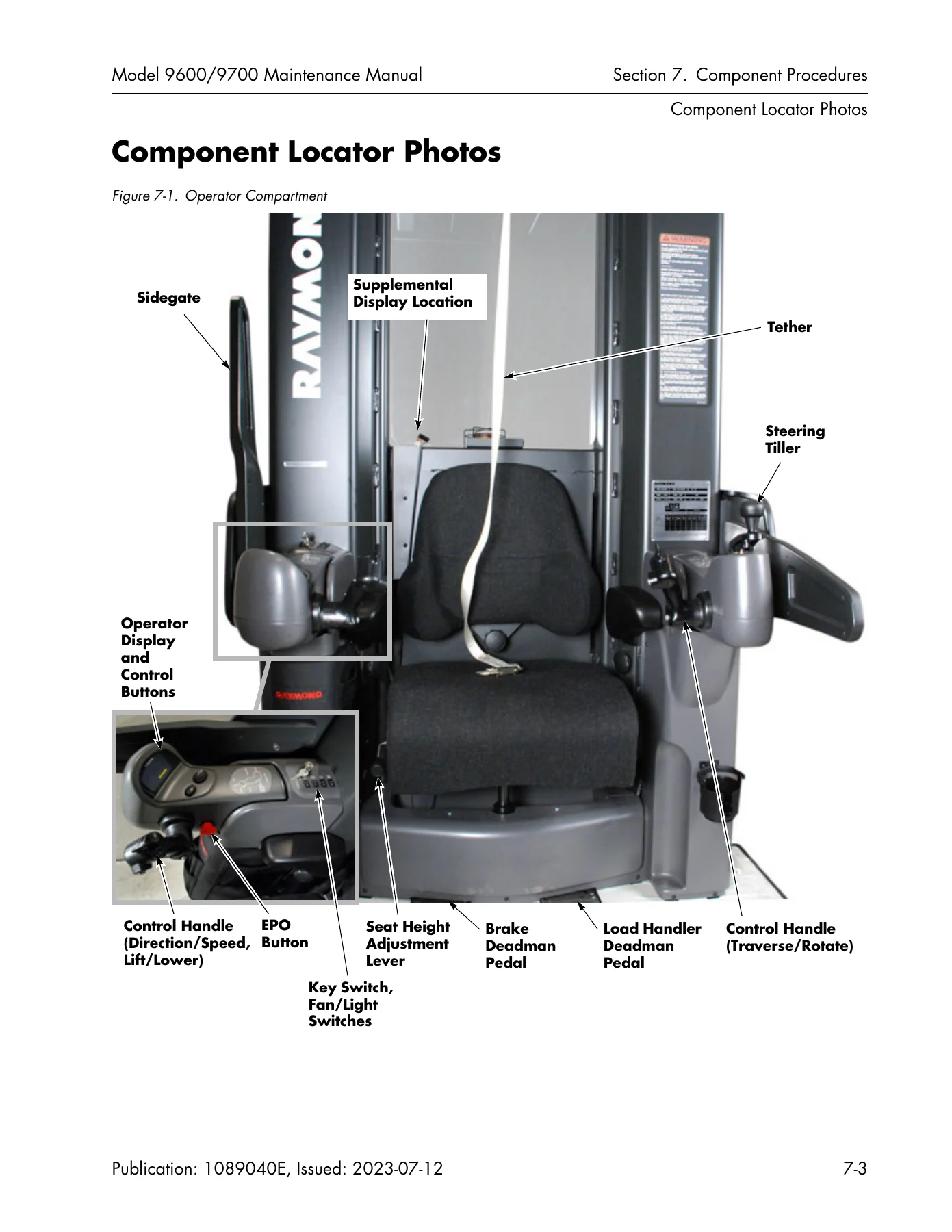
Component procedures walk through the actual removal, installation, and adjustment steps for the steer motor, pinion gear, control handle assembly, control handle return spring, travel/traverse pots, lift/lower/rotate pots, control handle switches, cold storage heater and thermostat, EPO switch, drive unit, drive tire pressing, deadman pedal, brake, battery, battery connector and cables, wiring and harness connectors (Molex, Universal Mate-N-Lok, AMPSEAL), power cables, DC motors, AC motors, Guidance Manager firmware replacement, mini-mast height proximity sensor, reach proximity switch, rotate position feedback pot (VR6), traverse position feedback pot (VR5), slack chain switch adjustment, cold storage conditioning, lift/lower pump, manifolds, bleeding the hydraulic system, lift pressure adjustment, load handler pressure adjustment, traverse pressure adjustment, main lift cylinders, flow limiters, main mast, main lift chains, lateral bearing adjustment, carriage, telescopic removal, mast puck/bearing replacement, height encoder belt replacement, mini-mast and load handler, traverse gear shaft, load handler lift chain, mini-mast pucks, and fork height and lift chain adjustment.
Diagnostics and Theory of Operation
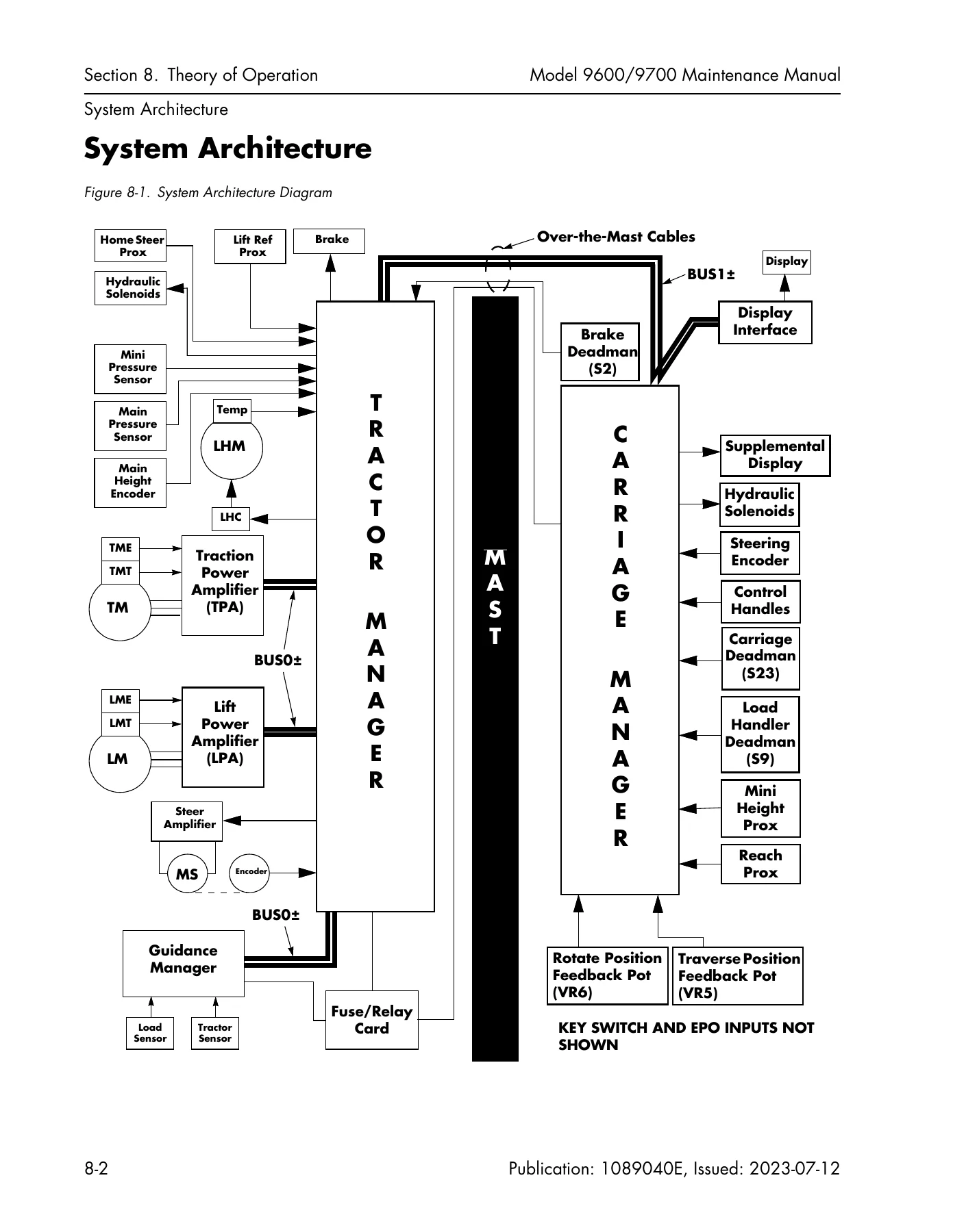
The theory of operation chapter explains system architecture, communication overview (BUS0 and BUS1), the Tractor Manager, Carriage Manager, Traction Power Amplifier, Lift Power Amplifier, Display Interface Card, Guidance Manager, lift/lower system, traction system, load handler system, steering system, wire guidance system, SelfTest sequences for each manager and amplifier, Emergency Power Off, and functional operation of the lift/lower, traction, load handler, steering, guidance, and end-of-aisle systems. Height calculation, weight calculation, and temperature sensing are explained. The pinout matrix is a complete terminal-by-terminal reference for the Carriage Manager, Tractor Manager, Fuse/Relay Card, Lift Power Amplifier, Traction Power Amplifier, Steer Amplifier, and antenna connectors, with function descriptions, normal levels, voltage source, and voltage user for every pin.
Hydraulic troubleshooting includes symptom tables for load handler traverse erratic, intermittent, noisy, slow, and one-direction-only operation; rotate erratic, intermittent, slow, noisy, and one-direction-only operation; reach erratic, intermittent, noisy, and slow operation; auto traverse and rotate and auto center nest failures; slow lift; intermittent lift; and travel problems. Electrical troubleshooting symptom tables cover motor overheating, motor arcing, BSOC reset or cutout failure, scrambled or intermittent display, operator display dark or inoperative, and display dark with lift truck not operational.
Schematics and Reference Data
The schematics section contains a six-sheet electrical schematic and a two-sheet hydraulic schematic for the 9600/9700. The appendix includes a lubrication specification chart with approved Raymond lubricants for control handle springs, drive unit gear case, hydraulic reservoir (non-CS and CS trucks), lift chains, and mast uprights and bearings, plus adhesives and sealants with Loctite numbers where applicable. The component specific service/torque chart lists torque values for the drive unit mounting bolts, bumper bolts, lift motor pump mounting bolts, load handler pump and motor mounting bolts, steer motor pinion gear mounting screw and mounting bolts, traction motor pinion gear mounting screw and motor mounting bolts, and wire guidance sensor bumper to tractor frame. Full torque charts for hydraulic fittings, straight thread face seal O-rings, standard ferrous, metric ferrous, standard brass, metric brass, and thread-forming screws are included, along with decimal equivalents and standard/metric conversions.
Who This Manual Is For
This Raymond 9600 & 9700 Swing-Reach maintenance manual is written for technicians who already have an expected level of expertise and need the technical information required to maintain, troubleshoot, and repair the truck. It is the document Raymond service personnel use. If you are responsible for keeping a 9600 or 9700 running, this manual gives you the fault codes, test procedures, component removal and installation steps, torque values, and system theory needed to do the job correctly. It covers both models in one volume, serial numbers 00001 and up, so it applies to the full production run of these Swing-Reach trucks.
Because the 9600 and 9700 share many systems but differ in mast and lift cylinder design, the manual distinguishes between them where it matters. Main lift cylinders are covered separately for 9600 and 9700, main lift chains are covered separately for 9600 and 9700, main mast lateral bearing adjustment is covered separately for 9600 and 9700, and mast puck/bearing replacement is covered separately for 9600 and 9700. The manual also covers the telescopic removal procedure for both models, and includes the smaller mini-mast and load handler assemblies that sit on the carriage.
The wire guidance and end-of-aisle systems are covered in depth because these are rail-guided and wire-guided trucks. The Learn Wire Guidance procedure is documented step by step for both the Guidance Manager with Filter Card (six-step process) and the Guidance Manager without Filter Card (three-phase process). Learn Rail Guidance is covered with the straight-line reference and steering adjustment procedure. End-of-aisle sensor location, input tests, and magnet position for deceleration and auto stop are included. Tracking values and coil values are explained so you can interpret what the Guidance Manager is sensing and diagnose wire guidance problems.
The manual also covers FlashWare, the software tool used to communicate with the truck. It explains how to install FlashWare on a Windows-compatible device, how to connect to the Tractor Manager and Carriage Manager, and what you can do from each connection point. This is useful if you need to update software, clear a manager, reset factory defaults, or enable and disable options.
If you work on Raymond Swing-Reach trucks, this manual belongs within reach. It is not a generic guide. It is the 9600/9700 maintenance manual, publication 1089040E, revision E, issued July 2023, and it applies to every 9600 and 9700 built from serial number 00001 onward. The fault code dictionary alone can save hours of diagnostic time. The test procedures let you verify circuits and components before you replace them. The torque charts and service limits help you reassemble to specification. The hydraulic and electrical schematics give you the system layout for tracing problems. And the theory of operation explains how the systems are supposed to work so you can reason through faults that do not match a specific code.
IMAGES PREVIEW
Instant PDF Delivery
This Raymond 9600 & 9700 Swing-Reach Lift Truck Maintenance Manual is delivered as an instant PDF download after payment. There is no shipping, no waiting for a physical book, and no restrictions on where you can use it. The file works on any device that can open a PDF — laptop, desktop, tablet, or phone. You can print the pages you need for the job and keep the rest on your device. If you are in the field, you can carry the whole manual with you. If you are in the shop, you can print the schematics and torque charts and post them where you need them. The PDF format means you can zoom in on wiring diagrams, search for a fault code, and jump to the section you need without flipping through hundreds of pages. This is the complete manual for the 9600 and 9700, at 475 pages, covering scheduled maintenance, troubleshooting, fault codes, component procedures, theory of operation, and schematics. Everything a technician needs to maintain, diagnose, and repair these Swing-Reach lift trucks is in this file.
Reviews
There are no reviews yet.