★ TRUSTED BY 321,897+ PROFESSIONALS WORLDWIDE
🏒
Trusted Business
Verified & Licensed
πŸ›‘οΈ
Virus Free Files
100% Safe Downloads
πŸ”’
Secure Payment
SSL Protected
⚑
Instant Delivery
Available Immediately
Sale!

Raymond EASi Reach-Fork EZ-C EZ-D EZ-CD EZ-DD Maintenance Manual 2013

Original price was: $39.95.Current price is: $24.95.

Complete 458-page Raymond EASi Reach-Fork maintenance manual for Series EZ-C, EZ-CD, EZ-D and EZ-DD lift trucks with the ACR System. Covers scheduled maintenance, troubleshooting, fault codes, diagnostic tests, component procedures, torque specs, hydraulic and electrical theory. Publication 1119847A, issued 02 Jan 2013. Instant PDF download.

⚑
Instant PDF Download
Available immediately
πŸ’Ύ
Save to Your Device
Download & keep forever
πŸ›‘οΈ
Antivirus Scanned
100% virus-free
🌍
Trusted Worldwide
175,000+ customers

Description

The Raymond EASi Reach-Fork EZ-C EZ-D Maintenance Manual is the consolidated 458-page service reference for the EASi Reach-Fork lift truck family running the ACR System β€” Series EZ-C, EZ-CD (previously DZ-C), EZ-D, and EZ-DD (previously DZ-D) β€” from serial number 00001 and up. Published by The Raymond Corporation as document 1119847A on 02 Jan 2013, this is the manual that replaced the earlier EASI Reach-Fork maintenance manuals #1019428A (EZ-C/DZ-C) and PDMM-0109 (EZ-D/DZ-D), making it the single source for the whole 36V AC traction line.

If you maintain, service, or repair one of these reach-fork trucks, this manual gives you the procedures, specifications, diagnostic routines, and theory you actually need. Every procedure is written against the EZ-C and EZ-D platforms β€” nothing generic, nothing borrowed from another truck.

File Details

  • Manual type: Maintenance / Service Manual
  • Manufacturer: The Raymond Corporation
  • Series covered: EZ-C, EZ-CD, EZ-D, EZ-DD (EASi Reach-Fork with ACR System)
  • Document number: 1119847A
  • Issue date: 02 Jan 2013
  • Language: English
  • Page count: 458 pages
  • File format: PDF
  • Serial coverage: S/N 00001 and up

Chapters Covered

  • Section 1 β€” How to Use This Manual: manual design, IETM usage, abbreviations and symbols
  • Section 2 β€” Safety: general safety, battery safety, static precautions, jacking safety, tie-down for transport, welding safety
  • Section 3 β€” Systems Overview: lift truck specifications, model and mast designations, battery specifications, FlashWare, operator display, modes of operation, passwords, Configure Mode menu
  • Section 4 β€” Scheduled Maintenance: maintenance guidelines, Maintenance Minder tool, initial 90-day / 250 HD service, 180-day / 500 HD service, 360-day / 2000 HD service, lubrication points, contactor tip inspection, chain and fork inspection
  • Section 5 β€” Troubleshooting: electrical troubleshooting, shorts to frame, battery state-of-charge, fuses and connectors, DC and AC motor testing, hydraulic troubleshooting guidelines and symptom tables
  • Section 6 β€” Messages, Codes, and Tests: power amplifier LED diagnostics, full message and fault code listing, analog tests, input tests, output tests
  • Section 7 β€” Component Procedures: special tools, decals and chassis, steering and controls, drive and brake, electrical components, hydraulic components, hydraulic cylinders, mast / chain / hose / cable, cold storage conditioning, fork height-tilt indicator
  • Section 8 β€” Theory of Operation: traction system, lift/aux system (AC and DC lift), thermal cut-back, steering system, HTI operation, full pinout matrix
  • Appendix A: lubrication specification chart, thread adhesives and sealants, component-specific service/torque chart, standard and metric torque charts, hydraulic fitting torques, straight thread face seal O-ring torques, decimal equivalent chart, standard/metric conversions
  • Index: alphabetical subject index

Read together, these sections take a technician from a dead lift truck through to a completed repair. Section 3 explains how the truck is built and configured, Section 4 lays out what to service and when, Section 5 narrows a symptom down to the failing circuit, Section 6 goes further with specific fault codes and live diagnostic tests you run through the operator display, Section 7 walks you through removal, installation, and adjustment of serviceable components, and Section 8 explains the electrical and hydraulic logic so you understand why a test behaves the way it does. That structure is what separates a real maintenance manual from a parts list.

Systems and Components Covered in Depth

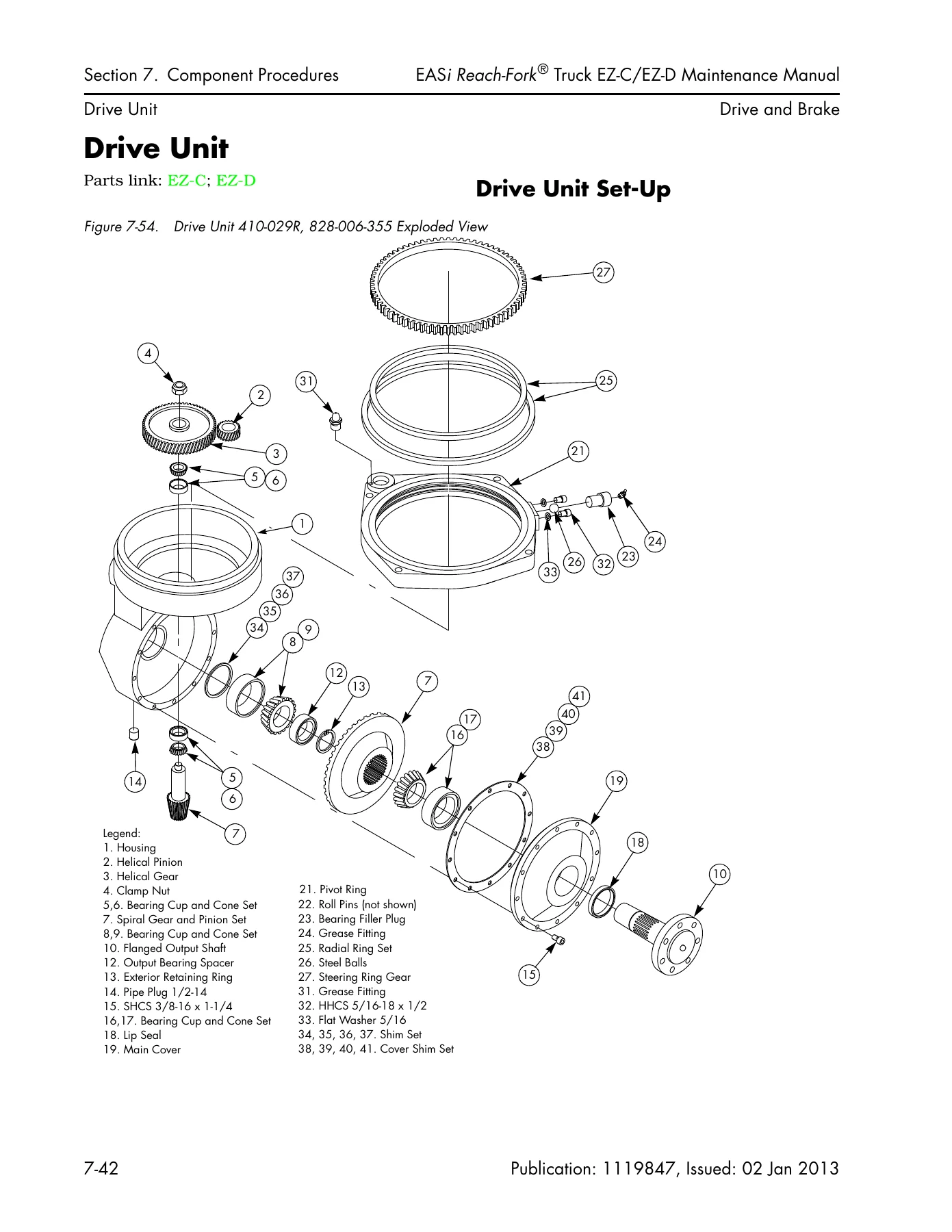
The EZ-C and EZ-D trucks are covered as complete systems, not isolated parts. The drive and brake section walks through the drive unit β€” set-up, radial ring inspection, disassembly, assembly, backlash measurement, and shim formulas β€” plus traction motor removal and installation, brake adjustment, upper brake pad replacement, O-ring seal replacement, brake bleeding, and the deadman (brake) pedal and master cylinder. Steering and controls covers the steering shaft and gear, caster assembly, steerable caster adjustment, and both the Fore/Aft Stance and Dockstance control handles down to the throttle pot (VR1), lift/lower pot (VR2), tilt/sideshift switch card, and horn and reach/retract switches.

On the hydraulic side you get the main manifold for AC and DC lift, reach manifold, tilt/sideshift manifolds, full port torque specifications, lift pressure adjustment, auxiliary system pressure adjustment, bypass flow regulator valve adjustment (FR1), steering system pressure adjustment, proportional lower valve adjustment, and counterbalance valve adjustment. Lift cylinders are covered in complete detail β€” front cluster, back cylinder with threaded anchor retention, side cylinder seal repacking, front and back cylinder seal repacking, lowering cushion, and flow control. Reach, tilt, and sideshift cylinders each get their own removal, disassembly, reassembly, and installation procedures.

Electrical coverage includes battery procedures, wiring and harness repair, Molex and AMP water-resistant connectors, power cable repair with lug crimping, power cable terminal torques, and both DC and AC motor service. The mast, chain, hose, and cable section covers over-the-mast hose and cable replacement and adjustment, mast shimming, mast bearing shimming, complete mast disassembly and shimming, reach carriage bearings, half shaft bearings, thrust bearings, lift chain adjustment and replacement, reach carriage lift chain anchors, equalization chains and sheaves, mechanical stop adjustment, and mast backlash adjustment.

Fault Codes and Diagnostic Tests

Section 6 is where this manual earns its keep on a modern reach truck. It lists every fault code the Vehicle Manager can display β€” including traction power amp overtemp (1H), low battery (1T), LPA overtemp (1V), traction motor approaching overtemp (2A), TPA and traction motor temp sensor out-of-range (2C, 2E), traction motor speed sensor failure (2H), TPA failure (2M), contactor codes (42, 43, 44, 45, 4B, 4C, 4D, 4E, 4F, 4G), CAN bus errors (59, 5A, 5B, 5G, 5J, 5L, 5M, 5N, 5P, VC), mast switch codes (61, 63, 6K), lift motor and LPA faults (6F, 6S, 6T, 6V, 6W, 6X, 6Y), throttle and lift pot out-of-range (80, 81, 83, 8F), operator compartment sensor codes (58, 8A), and VM/display faults (A0, AG, AH, AJ, AK, AL, EC, E1, E2, F4, F5, F8, FG, FH).

For each code you get the test to run and the corrective action. The tests themselves β€” analog, input, and output β€” are laid out as diagnosis and repair tables with probe points, meter scale, expected readings, and both pass and fail branches. That includes Test A04 throttle pot voltage, A05 lift/lower pot voltage, A08 traction motor temperature, A09 lift motor temperature, A10 TPA temperature, A11 traction motor current, A19 LPA temp, A20 lift motor current, A22 traction throttle request, A23 lift throttle request, A24 TPA internal temperature, A25 LPA internal temperature, A26 +5VDC supply, plus input tests such as the deadman switch (I00), nested switch (I01), speed limiting switches (I02, I03), lift inhibit bypass (I04), lift limit (I05), reach and retract switches (I06, I07), tilt switches (I08, I09), sideshift switches (I10, I11), fuse tests (I13, I14), horn (I15), motor speed sensors (I19, I20), staging switch (I21), lift cutout (I22), CAN bus (I23), and the OCSS upper and lower beam tests (I80, I81). Output tests cover contactors (O00, O01, O02), solenoids (O04 through O12), horn and alarms (O18, O19, O20), fans (O23), lift blocking (O24), aux select (O25), aux boost 1 and 2 (O26, O27), and ramp tests for the lift and traction power amplifiers (O28, O29).

Key Specifications You Will Find Inside

The Appendix alone is worth the download. The Lubrication Specification Chart lists approved fluids and greases by application β€” drive unit gear case 75W-90 synthetic gear oil, ISO VG 46 hydraulic fluid for non-cold-storage trucks, ISO VG 32 and MIL-H-5606E for cold storage, NLGI 2 grease for mast uprights and bearings, and Teflon grease for lift chains. The Component Specific Service/Torque Chart gives you the exact torque for hundreds of fasteners β€” power amplifier cables at 95 to 104 in. lb., traction motor top nut at 204 to 221 in. lb., bottom nut at 128 to 133 in. lb., drive wheel mounting bolts at 170 ft. lb., mast-to-tractor bolts at 165 ft. lb., overhead guard at 130 ft. lb., and so on. Standard and metric torque charts, hydraulic fitting torques, and straight thread face seal O-ring torques are all included, along with decimal equivalents and standard/metric conversions.

Pressure settings are spelled out too. Lift relief pressure is 3200 psi for 1.75 in. cylinders up to 330 in. elevated height, 3500 psi for 1.75 in. cylinders from 331 to 371 in., and 2900 psi for 2.00 in. cylinders up to 421 in. Auxiliary system pressure is 2000 psi on AC lift and 1600 psi on DC lift. Steering system pressure is 1600 psi on AC lift. Battery voltage range is 32 to 39V. Brake gap is 0.008 in. between the adjuster bushing and motor housing. Thermal down-rating tables list the exact temperatures at which the truck reduces performance and shuts down. All values are printed exactly as Raymond specifies them.

Battery specifications for the 36V line are also included β€” EZ-C and EZ-CD widths of 18.5 and 21.5 in. with weights from 2300 to 2900 lb.; EZ-D widths of 16.5 and 18.5 in. with weights from 2000 to 2600 lb.; EZ-DD widths of 16.5 and 18.5 in. with weights from 1600 to 2600 lb. All series are rated at 6 hours with maximum 1240 amp hours, and the UL note requiring no more than 0.5 in. of horizontal battery movement is stated.

Cold Storage, HTI, and Options

For cold storage operations, the manual documents the required components β€” heated control handle assemblies, cold storage deadman switch, cold storage contactor/fuse panel, wire mesh mast guard, optional heated floor pad β€” plus the correct lubricants and sealing treatments. The Fork Height-Tilt Indicator (HTI) gets its own section with component locations, active maintenance mode, cable replacement, encoder assembly, display card, calibrating and setting the height indicator, fork carriage shimming, and the HTI pressure switch.

What This Manual Enables You to Do

With the Raymond EASi Reach-Fork EZ-C EZ-D maintenance manual in hand, you can perform the full scheduled maintenance routine at 90-day, 180-day, and 360-day or 250, 500, and 2000 deadman-hour intervals; diagnose electrical and hydraulic faults down to the individual circuit using Raymond’s own fault codes and test routines; remove, disassemble, reassemble, and reinstall major components including the drive unit, traction motor, brake, steering shaft and gear, control handle, lift cylinders, reach cylinder, tilt cylinder, sideshift cylinder, and mast; adjust pressures, torque values, chain tension, and mast shimming to factory specification; and understand the theory of operation behind the traction, lift/aux, steering, and thermal cut-back systems so you can reason through problems the code list does not cover.

Having the right procedures and the right specifications matters because these trucks run 36V electrical systems with CAN bus communications between the Vehicle Manager and the power amplifiers, hydraulic pressures up to 3500 psi, and lift capacities from 2500 to 4500 lb. Guessing at a torque value, a pressure setting, or a fault-code corrective action is how a repair turns into a return visit. This manual removes the guesswork.

Complete PDF Bookmark Tree

Complete Bookmarks

The complete bookmarks in the β€œRaymond EASi Reach-Fork EZ-C EZ-D EZ-CD EZ-DD Maintenance Manual 2013” are as follows:

Front Coverp. 1
Table of Contentsp. 3
Document Revision Historyp. 5
Service Information Listp. 6
Section 1. How to Use This Manualp. 7
Manual Designp. 8
Interactive Electronic Technical Manualsp. 9
Abbreviations and Symbolsp. 10
Section 2. Safetyp. 13
Definitionsp. 14
General Safetyp. 15
Battery Safetyp. 17
Static Precautionsp. 19
Jacking Safetyp. 20
To elevate the rear of the lift truck:p. 20
To elevate either side of the lift truck:p. 20
Tie-Down for Transportp. 22
Welding Safetyp. 23
Section 3. Systems Overviewp. 25
Introductionp. 26
Lift Truck Specificationsp. 27
Load Capacityp. 27
Model Designationsp. 28
Mast Seriesp. 28
Serial Numberp. 28
Battery Specificationsp. 29
FlashWarep. 30
Overviewp. 30
Requirementsp. 30
Installing FlashWare on PCp. 30
Connecting PC to Truckp. 30
Starting FlashWarep. 30
Operator Displayp. 32
Modes of Operationp. 33
Overviewp. 33
Run Mode Tonesp. 34
Entering Program Modep. 34
Using Configure Modep. 35
Configure Mode Menup. 38
Using Learn Modep. 41
Using Maintenance Modep. 41
Section 4. Scheduled Maintenancep. 45
Maintenance Guidelinesp. 46
Maintenance Minder β„’ Toolp. 47
Factory Configurationp. 47
Enablingp. 47
Setting or Changing Time Interval and Action Optionp. 47
Resetting Maintenance Minderp. 48
Disablingp. 48
Exiting Program Modep. 48
Initial 90 Day/250 Deadman Hours (HD) Maintenancep. 49
Every 180 Days or 500 HDp. 50
Every 360 Days or 2000 HDp. 53
Lubrication Pointsp. 54
Contactor Tip Inspectionp. 59
Chain Maintenancep. 60
Lift Chain Inspectionp. 60
Condition-Cause Chartp. 60
Fork Inspectionp. 61
Surface Inspectionp. 61
Straightness of Blade and Shankp. 61
Fork Anglep. 62
Fork Tip Heightp. 62
Positioning Locks (if applicable)p. 62
Wearp. 63
Section 5. Troubleshootingp. 65
Electrical Troubleshootingp. 66
Generalp. 66
Shorts to Framep. 66
Battery State-of-Chargep. 69
Fusesp. 70
Electrical Connectionsp. 71
DC Motorsp. 74
AC Motorsp. 78
Hydraulic Troubleshooting Guidelinesp. 79
Symptom Tables: Hydraulic Functionsp. 80
Auxiliary Functionsp. 80
Lift/Lower Systemp. 84
Symptom Tables: Travel Functionsp. 88
Slow Travel or Sluggish Accelerationp. 88
Symptom Tables: Electrical Symptomsp. 89
Motor Overheatingp. 89
Symptom Tables: Operator Display Problemsp. 90
Scrambled or Intermittent Displayp. 90
Symptom Tables: Dead Lift Truckp. 91
Display is Dark; Lift Truck is NOT Operationalp. 91
Section 6. Messages, Codes, and Testsp. 93
Power Amplifier LED Diagnosticsp. 94
Messages and Codes Summary Listp. 95
Messages and Codesp. 97
Electrical Test Summary Listp. 113
Analog Testsp. 113
Input Testsp. 113
Output Testsp. 114
Analog Testsp. 115
Test A04 – Throttle Pot (VR1) Voltagep. 116
Run Testp. 116
Diagnosis and Repairp. 116
Test A05 – Lift/Lower Pot Voltagep. 117
Run Testp. 117
Diagnosis and Repairp. 117
Test A08 – Traction Motor Temperaturep. 118
Limitsp. 118
Run Testp. 118
Diagnosis and Repairp. 118
Test A09 – Lift Motor Temperaturep. 119
Limitsp. 119
Run Testp. 119
Diagnosis and Repairp. 120
Test A10 – TPA Temperaturep. 121
Limitsp. 121
Run Testp. 121
Diagnosis and Repairp. 121
Test A11 – Traction Motor Currentp. 122
Limitsp. 122
Run Testp. 122
Diagnosis and Repairp. 122
Test A13 – Pressure Sensor Voltagep. 123
Run Testp. 123
Diagnosis and Repairp. 123
Test A14 – +12VDC Power Supplyp. 124
Run Testp. 124
Diagnosis and Repairp. 124
Test A15 – Battery Voltagep. 125
Run Testp. 125
Diagnosis and Repairp. 125
Test A19 – LPA Tempp. 126
Limitsp. 126
Run Testp. 126
Diagnosis and Repairp. 126
Test A20 – Lift Motor Current (AC Lift)p. 127
Limitsp. 127
Run Testp. 127
Diagnosis and Repairp. 127
Test A22 – Traction Throttle (VR1) Requestp. 128
Run Testp. 128
Diagnosis and Repairp. 128
Test A23 – Lift Throttle (VR2) Requestp. 129
Run Testp. 129
Diagnosis and Repairp. 129
Test A24 – TPA Tempp. 130
Limitsp. 130
Run Testp. 130
Diagnosis and Repairp. 130
Test A25 – LPA Internal Temperaturep. 131
Limitsp. 131
Run Testp. 131
Diagnosis and Repairp. 131
Test A26 – +5VDC Power Supplyp. 132
Run Testp. 132
Diagnosis and Repairp. 132
Test A27 – Power Amplifier Fans Voltagep. 133
Input Testsp. 135
Test I00 – Deadman Switch (S2)p. 136
Run Testp. 136
Diagnosis and Repairp. 136
Test I01 – Nested Switch (S19)p. 137
Run Testp. 137
Diagnosis and Repairp. 137
Test I02 – 1st Speed Limiting Switch (S10)p. 138
Run Testp. 138
Diagnosis and Repairp. 138
Test I03 – 2nd Speed Limiting Switch (S11)p. 139
Run Testp. 139
Diagnosis and Repairp. 139
Test I04 – Lift Inhibit Bypass Switch (S12)p. 140
Run Testp. 140
Diagnosis and Repairp. 140
Test I05 – Lift Limit Switch (S13)p. 141
Run Testp. 141
Diagnosis and Repairp. 141
Test I06 – Reach Switch (S4)p. 142
Run Testp. 142
Diagnosis and Repairp. 142
Test I07 – Retract Switch (S5)p. 143
Run Testp. 143
Diagnosis and Repairp. 143
Test I08 – Tilt Up Switch (S6)p. 144
Run Testp. 144
Diagnosis and Repairp. 144
Test I09 – Tilt Down Switch (S7)p. 145
Run Testp. 145
Diagnosis and Repairp. 145
Test I10 – Sideshift Right Switch (S9)p. 146
Run Testp. 146
Diagnosis and Repairp. 146
Test I11 – Sideshift Left Switch (S8)p. 147
Run Testp. 147
Diagnosis and Repairp. 147
Test I13 – Lift Fuse (FU3) (DC Lift)p. 148
Run Testp. 148
Diagnosis and Repairp. 148
Test I14 – Steering Fuse (FU1) (AC Lift)p. 149
Run Testp. 149
Diagnosis and Repairp. 149
Test I14 – Auxiliary Fuse (FU1) (DC Lift)p. 150
Run Testp. 150
Diagnosis and Repairp. 150
Test I15 – Horn Switch (S3)p. 151
Run Testp. 151
Diagnosis and Repairp. 151
Test I19 – Traction Motor Speed Sensorp. 152
Run Testp. 152
Diagnosis and Repairp. 152
Test I20 – Lift Motor Speed Sensor (AC Lift)p. 153
Run Testp. 153
Diagnosis and Repairp. 153
Test I21 – Staging Switch (S14) (AC Lift)p. 154
Run Testp. 154
Diagnosis and Repairp. 154
Test I22 – Lift Cutout Switch (S20) (AC Lift)p. 155
Run Testp. 155
Diagnosis and Repairp. 155
Test I23 – CAN Bus Testp. 156
Run Testp. 156
Diagnosis and Repairp. 156
Test I80 – OCSS Upper Beamp. 158
Run Testp. 158
Diagnosis and Repairp. 158
If the LEDs do not illuminate as described above, troubleshoot as follows:p. 159
Test I81 – OCSS Lower Beamp. 160
Run Testp. 160
Diagnosis and Repairp. 160
Output Testsp. 163
Test O00 – Toggle the TPC Contactorp. 164
Run Testp. 164
Diagnosis and Repairp. 164
Test O01 – Toggle the STR Contactor (AC Lift)p. 165
Run Testp. 165
Diagnosis and Repairp. 165
Test O01 – Toggle the PC Contactor (DC Lift)p. 166
Run Testp. 166
Diagnosis and Repairp. 166
Test O02 – Toggle the LPC Contactor (AC Lift)p. 167
Run Testp. 167
Diagnosis and Repairp. 167
Test O02 – Toggle the P Contactor (DC Lift)p. 168
Run Testp. 168
Diagnosis and Repairp. 168
Test O04 – Toggle the DIRA (SOL5B) Solenoidp. 169
Run Testp. 169
Diagnosis and Repairp. 169
Test O05 – Toggle the DIRB (SOL5T) Solenoidp. 170
Run Testp. 170
Diagnosis and Repairp. 170
Test O06 – Toggle the Reach Solenoidp. 171
Run Testp. 171
Diagnosis and Repairp. 171
Test O07 – Toggle the Tilt Solenoidp. 172
Run Testp. 172
Diagnosis and Repairp. 172
Test O08 – Toggle the Sideshift Solenoidp. 173
Run Testp. 173
Diagnosis and Repairp. 173
Test O09 – Toggle the EQ (SOL6) Solenoidp. 174
Run Testp. 174
Diagnosis and Repairp. 174
Test O10 – Toggle 2nd Pump Solenoid (DC Lift)p. 175
Run Testp. 175
Diagnosis and Repairp. 175
Test O11 – Toggle the Load Hold (SOL1) Solenoidp. 176
Run Testp. 176
Diagnosis and Repairp. 176
Test O12 – Ramp the Proportional Lower (SOL2) Solenoid (AC Lift)p. 177
Run Testp. 177
Diagnosis and Repairp. 177
Test O12 – Ramp the Proportional Lift/Lower Solenoid (DC Lift)p. 178
Run Testp. 178
Diagnosis and Repairp. 178
Test O18 – Toggle the Hornp. 179
Run Testp. 179
Diagnosis and Repairp. 179
Test O19 – Audible Alarmp. 180
Run Testp. 180
Diagnosis and Repairp. 180
Test O20 – Travel Alarmp. 181
Run Testp. 181
Diagnosis and Repairp. 181
Test O23 – Toggle Fansp. 182
Run Testp. 182
Diagnosis and Repairp. 182
Test O24 – Toggle the Lift Blocking (SOL7) Solenoid (AC Lift)p. 183
Run Testp. 183
Diagnosis and Repairp. 183
Test O25 – Toggle the Aux Select (SOL4) Solenoid (AC Lift)p. 184
Run Testp. 184
Diagnosis and Repairp. 184
Test O26 – Toggle the Aux Boost 2 (SOL8) Solenoid (AC Lift)p. 185
Run Testp. 185
Diagnosis and Repairp. 185
Test O27 – Toggle the Aux Boost 1 (SOL3) Solenoid (AC Lift)p. 186
Run Testp. 186
Diagnosis and Repairp. 186
Test O28 – Ramp the Lift Power Amplifierp. 187
Run Testp. 187
Diagnosis and Repairp. 187
Test O29 – Ramp the TPAp. 188
Run Testp. 188
Diagnosis and Repairp. 188
Section 7. Component Proceduresp. 189
List of Component Proceduresp. 190
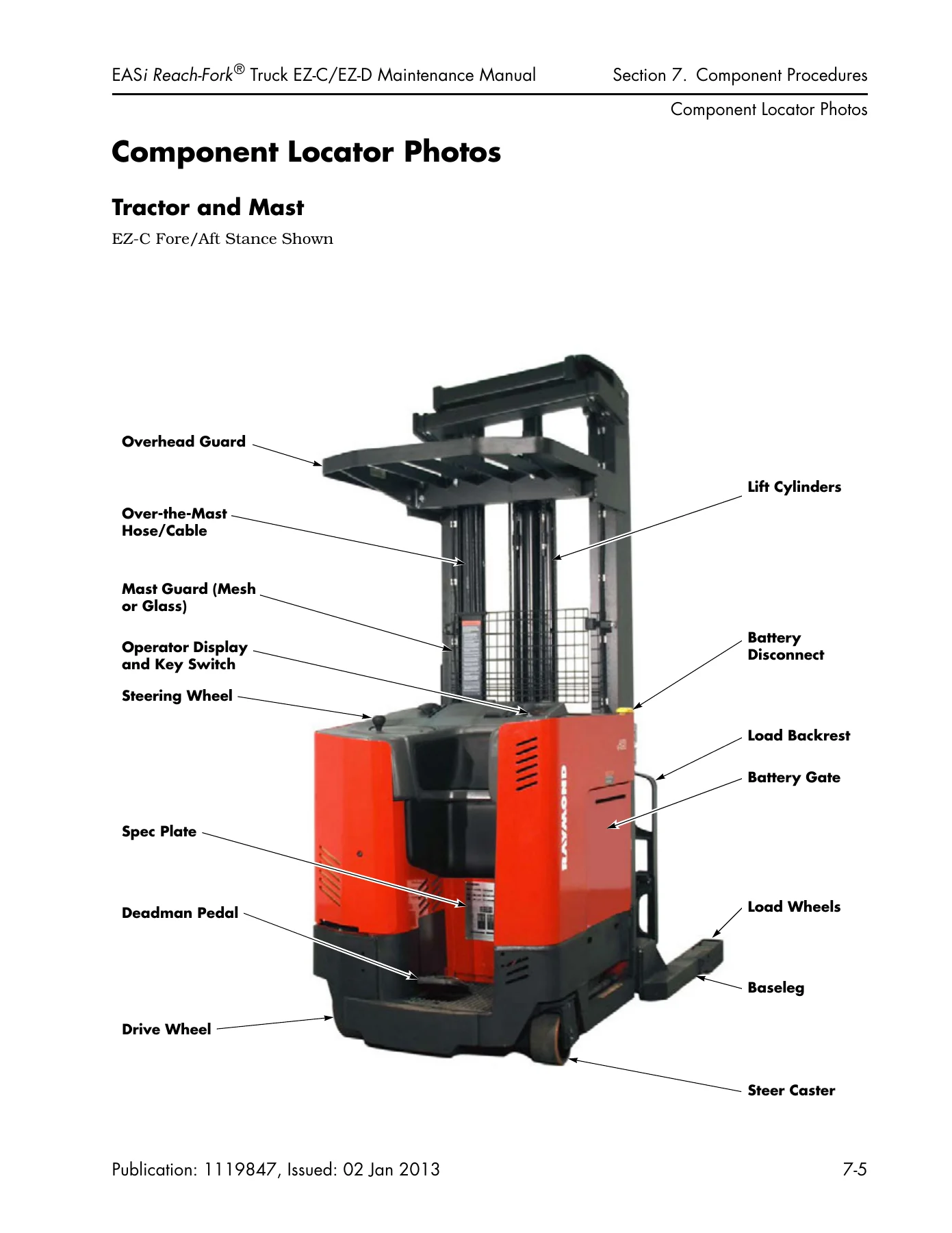
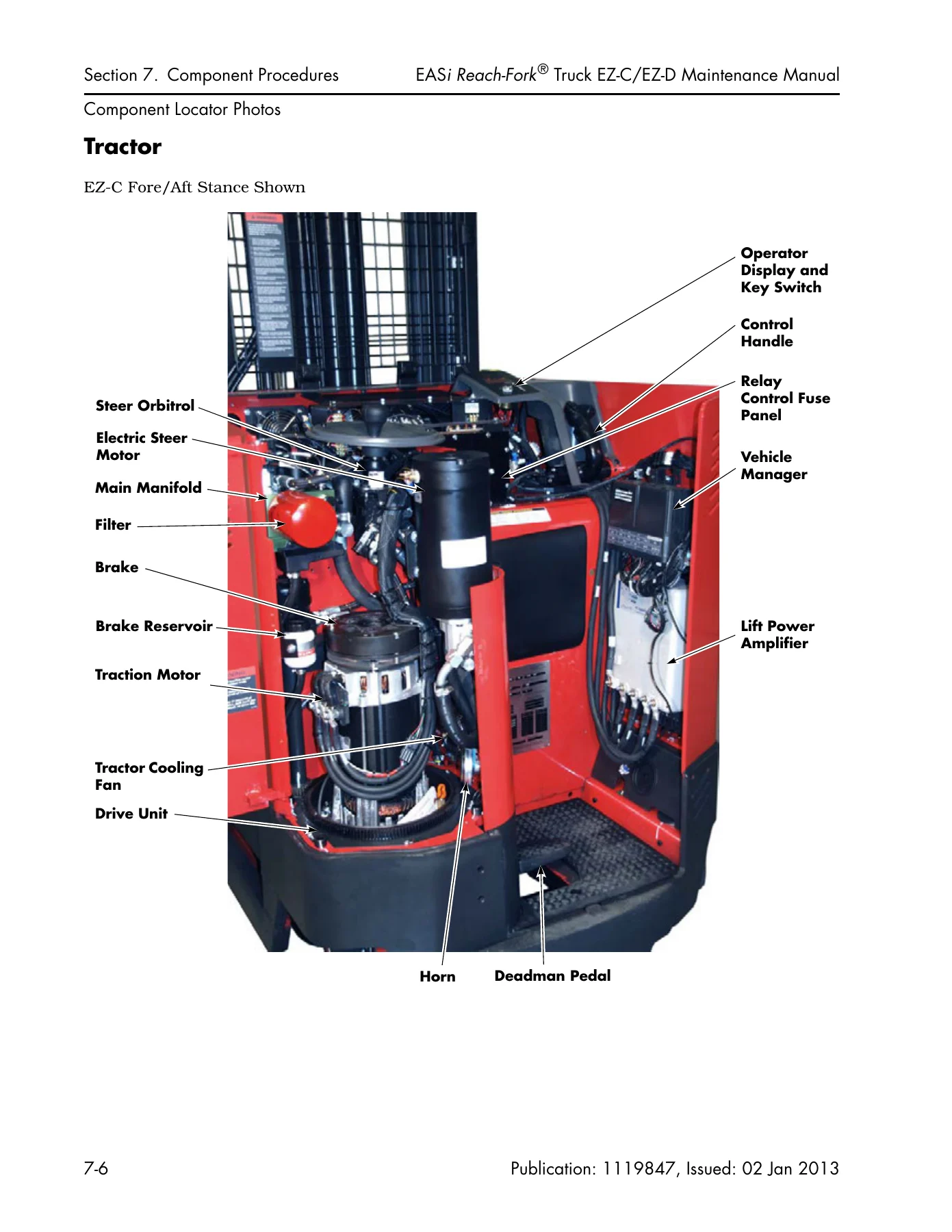
Component Locator Photosp. 193
Tractor and Mastp. 193
Tractorp. 194
Tractor Deckp. 195
Carriagep. 196
Underside Componentsp. 197
Special Tools, Decals, and Chassisp. 199
Special Toolsp. 200
Decals and Platesp. 201
Steering and Controlsp. 205
Steering Shaft and Gearp. 206
Removalp. 206
Installationp. 207
Caster Assemblyp. 208
Removalp. 208
Installationp. 208
Steerable Casterp. 209
Initial Adjustmentp. 209
Caster Height Adjustmentp. 210
Steering Linkagep. 212
Control Handlep. 213
Fore/Aft Stance Handlep. 213
Dockstance Control Handlep. 220
Drive and Brakep. 229
Drive Unitp. 230
Drive Unit Set-Upp. 230
Standard and Special Toolsp. 231
Troubleshootingp. 232
Kit Optionsp. 233
Radial Ring Inspectionp. 234
Removalp. 234
Disassemblyp. 235
Assemblyp. 239
Installationp. 245
Traction Motorp. 246
Removalp. 246
Installationp. 246
Brakep. 249
Brake Adjustmentp. 250
Brake Pad Inspectionp. 250
Upper Brake Pad Replacementp. 250
Brake Assemblyp. 252
Brake O-ring Seal Replacementp. 254
Bleeding Brakep. 254
Deadman (Brake) Pedalp. 255
Inspectionp. 255
Adjustmentp. 255
Deadman Switch (S2)p. 256
Removalp. 256
Installation and Adjustmentp. 256
Brake Master Cylinderp. 258
Removalp. 258
Installation and Bleedingp. 259
Inertial Dampenerp. 261
Removalp. 261
Installation and Adjustmentp. 262
Electrical Componentsp. 265
Battery Proceduresp. 266
Battery Connector/Cablesp. 266
Battery Exterior Cleaningp. 267
Testing, Charging, and Maintenancep. 267
Battery State-of-Chargep. 268
Wiring and Harness Repairp. 269
General Proceduresp. 269
Molex Connectorsp. 270
AMP Water-Resistant Connectorsp. 271
AMP Harness/Power Amp Connectorp. 274
Power Cablesp. 277
Power Cable Repairp. 277
Motorsp. 279
Power Cable Terminalsp. 279
DC Motor Troubleshootingp. 279
AC Motor Troubleshootingp. 279
DC Motor Servicep. 279
AC Motor Servicep. 281
Hydraulic Componentsp. 285
Hydraulic Fluid Replacementp. 286
Preparationp. 286
Draining the Reservoir (AC Lift Only)p. 286
Purging the Auxiliary Systemp. 287
Purging the Steering Systemp. 287
Purging the Lift Cylindersp. 287
Refilling the Systemp. 288
Bleeding the Systemp. 288
Lift Pressure Adjustmentp. 289
AC Liftp. 289
DC Liftp. 289
Manual Lowering of Fork Carriagep. 291
AC Liftp. 291
DC Liftp. 291
Proportional Lower Valve Adjustmentp. 293
Auxiliary System Pressure Adjustmentp. 294
AC Liftp. 294
DC Liftp. 294
Bypass Flow Regulator Valve Adjustment (FR1) – AC Liftp. 296
Steering System Pressure Adjustment – AC Liftp. 297
Main Manifold – AC Liftp. 298
Main Manifold – DC Liftp. 299
Reach Manifoldp. 300
Tilt/Sideshift Manifoldsp. 301
Manifold Port Torque Specificationsp. 302
Counterbalance Valve Adjustmentp. 304
Hydraulic Components, Cylinderp. 306
Lift Cylindersp. 307
Lift Cylinder, Front Clusterp. 311
Lift Cylinder, Back Cylinder, Threaded Anchor Retentionp. 313
Removalp. 313
Installationp. 313
Adjustmentp. 314
Lift Cylinder, Side Cylinder Seal Repackingp. 316
Removalp. 316
Repacking and Assemblyp. 316
Lift Cylinder, Front and Back Cylinder Seal Repackingp. 318
Removalp. 318
Repacking and Assemblyp. 318
Lift Cylinder Lowering Cushionp. 319
Removalp. 319
Installationp. 319
Flow Controlp. 320
Removalp. 320
Installationp. 321
Reach Cylinderp. 322
Removalp. 322
Disassemblyp. 323
Reassemblyp. 325
Installationp. 325
Adjustmentp. 326
Tilt Cylinderp. 328
Removalp. 328
Installationp. 329
Disassemblyp. 329
Reassemblyp. 330
Sideshift Cylinderp. 331
Removalp. 331
Installationp. 331
Disassembly/Reassemblyp. 331
Mast, Chain, Hose, Cablep. 334
Over-the-Mast Hose/Cablep. 335
Removalp. 335
Installationp. 336
Adjustmentp. 336
Mast Shimmingp. 338
Mast Bearing Shimmingp. 338
Mast Disassembly and Shimmingp. 340
Bearings, Reach Carriagep. 345
Removalp. 345
Installationp. 345
Bearings, Reach Half Shaftp. 346
Removalp. 346
Installationp. 346
Bearings, Reach Thrustp. 347
Bearing Assemblyp. 347
Reach Carriagep. 349
Removalp. 349
Installationp. 350
Lift Chains, Mainp. 351
Adjustmentp. 351
Removalp. 351
Installationp. 351
Reach Carriage Lift Chain Anchorsp. 353
Upper (Adjustable) Chain Anchorp. 353
Lower Chain Anchorsp. 353
Equalization Chainsp. 355
Adjustmentp. 355
Lubricationp. 355
Removalp. 356
Installationp. 356
Equalization Chain Sheavep. 358
7- or 8-Inch (18- or 20-cm) Deep Mast Uprightsp. 358
9-Inch (23-cm) Deep Mast Uprightsp. 359
Mechanical Stop Adjustmentp. 360
Mast Backlash Adjustmentp. 361
Adjustmentp. 361
Optionsp. 362
Cold Storage Conditioningp. 363
Componentsp. 363
Lubricantsp. 363
Sealing Treatmentp. 363
Corrosion Inhibitor Coatingp. 363
Fork Height-Tilt Indicator (HTI)p. 364
Fork Height Indicatorp. 364
Fork Tilt Indicatorp. 364
HTI Active Maintenance Modep. 364
HTI Component Locationp. 367
Fork Height Indicator Cable Replacementp. 369
HTI Encoder Assemblyp. 370
HTI Display Cardp. 371
Calibrating and Setting the Height Indicatorp. 372
Fork Tilt Indicatorp. 373
HTI Pressure Switch (S31)p. 373
Section 8. Theory of Operationp. 376
Traction System Functional Operationp. 377
Connecting the Batteryp. 377
Turning Key Switch (S1) ONp. 377
Closing Deadman Switch (S2)p. 378
Requesting Travelp. 379
Proportional Pluggingp. 379
Lift/Aux System (AC Lift)p. 380
System Componentsp. 380
Theory of Functionp. 383
Lift/Aux System (DC Lift)p. 390
System Componentsp. 390
Theory of Functionp. 392
Thermal Cut-Backp. 395
Steering Systemp. 396
AC Liftp. 396
DC Liftp. 396
HTI Theory of Operationp. 397
Fork Height Indicatorp. 397
Fork Tilt Indicatorp. 397
Pinout Matrixp. 398
Section A. Appendixp. 416
Lubrication Specification Chartp. 417
Thread Adhesives, Sealants, and Lubricantsp. 418
Component Specific Service/Torque Chartp. 419
Torque Chart – Standard (Ferrous)p. 422
Torque Charts – Metricp. 423
Torque Chart – Thread-Forming Screwsp. 424
Torque Chart – Hydraulic Fittingsp. 425
Torque Chart – Straight Thread Face Seal O-Ringsp. 426
Decimal Equivalent Chartp. 427
Standard/Metric Conversionsp. 429
Section I. Indexp. 430
EZC Schematics
Figure 1. Power Distribution Diagram [S/N 25139 and below]p. 443
Figure 2. Power Distribution Diagram [S/N 25140 and above]p. 444
Figure 3. Electrical Schematic (Sheet 1 of 4) [S/N 25139 and below]p. 445
Figure 4. Electrical Schematic (Sheet 1 of 4) [S/N 25140 and above]p. 446
Figure 5. Electrical Schematic, Options (Sheet 2 of 4)p. 447
Figure 6. Electrical Schematic, Options (Sheet 3 of 4)p. 448
Figure 7. Electrical Schematic, Legend (Sheet 4 of 4)p. 449
Figure 8. Hydraulic Schematic (Sheet 1 of 2)p. 450
Figure 9. Hydraulic Schematic (Sheet 2 of 2)p. 451
EZD Schematics
Figure 1. Power Distribution Diagramp. 453
Figure 2. Electrical Schematic (Sheet 1 of 4)p. 454
Figure 3. Electrical Schematic, Options (Sheet 2 of 4)p. 455
Figure 4. Electrical Schematic, Options (Sheet 3 of 4)p. 456
Figure 5. Electrical Schematic, Legend (Sheet 4 of 4)p. 457
Figure 6. Hydraulic Schematicp. 458


IMAGES PREVIEW

Raymond EASi Reach-Fork EZ-C EZ-D EZ-CD EZ-DD Maintenance Manual 2013 β€” PDF page 193 preview
Raymond EASi Reach-Fork EZ-C EZ-D EZ-CD EZ-DD Maintenance Manual 2013 β€” PDF page 194 preview
Raymond EASi Reach-Fork EZ-C EZ-D EZ-CD EZ-DD Maintenance Manual 2013 β€” PDF page 230 preview

Delivery is instant. The moment your order completes you get the PDF β€” no shipping, no waiting, no physical book to keep track of. Download it, open it on any device, and print the pages you need for the job. Whether you are in the shop, on the warehouse floor, or out at a customer site, the complete Raymond EASi Reach-Fork service reference stays with you.
Reviews

There are no reviews yet.

Be the first to review “Raymond EASi Reach-Fork EZ-C EZ-D EZ-CD EZ-DD Maintenance Manual 2013”

What Our Customers Say

β˜…β˜…β˜…β˜…β˜… Live reviews from customers
Loading customer reviews...
0
    0
    Your Cart
    Your cart is emptyReturn to Shop
    πŸ›’
    Recently Purchased
    πŸ•’ verified order