
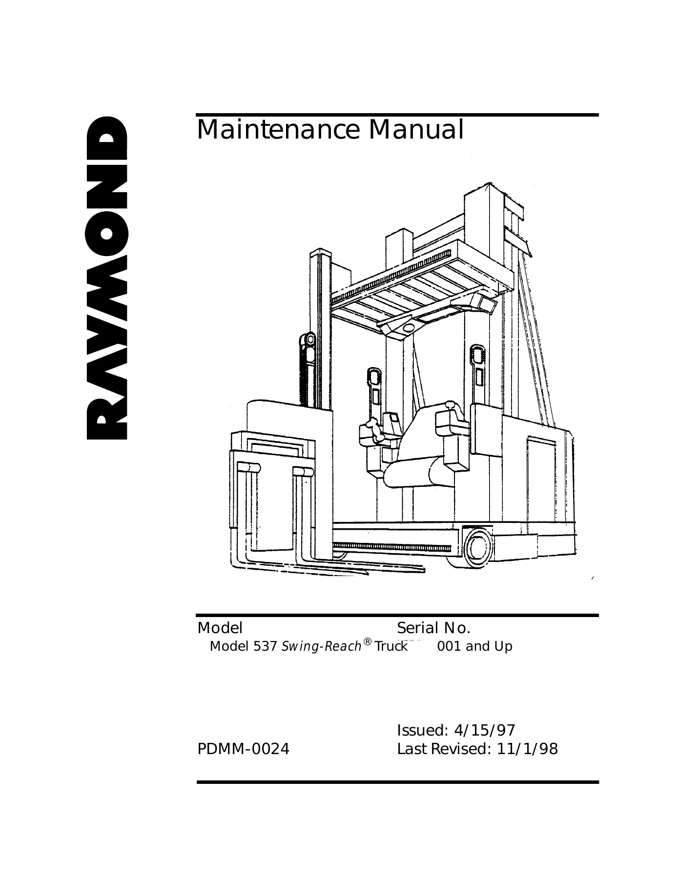
Raymond Model 537 Swing-Reach Truck Maintenance Manual PDMM-0024 – PDF
Original price was: $39.95.$24.95Current price is: $24.95.
Complete Raymond Model 537 Swing-Reach truck maintenance manual, publication PDMM-0024, covering serial 001 and up. Full theory of operation, scheduled maintenance, troubleshooting codes, analog/input/output tests, hydraulic and electrical schematics, and load handler rebuild procedures for the intellidrive2 and EASi2 equipped 537.
Description
Raymond Model 537 Swing-Reach Truck Maintenance Manual PDMM-0024
This Raymond Model 537 Swing-Reach Truck Maintenance Manual is the full service and repair document issued by The Raymond Corporation under publication number PDMM-0024, released 4/15/97 and last revised 11/1/98. It applies to Model 537 Swing-Reach trucks from serial 001 and up, including units running the EASi2 electronic architecture and the intellidrive2 control platform. Across roughly 766 pages it carries the complete maintenance, diagnostic and overhaul information a technician needs to keep a 537 running to specification — from the daily eight-hour check sheet through to cylinder packing replacement, wire guidance alignment and troubleshooting code interpretation.
File Details
- Manual type: Maintenance / service and repair manual
- Brand: The Raymond Corporation
- Model: Model 537 Swing-Reach® Truck
- Serial coverage: 001 and Up
- Publication number: PDMM-0024
- Issued: 4/15/97
- Last revised: 11/1/98
- Language: English
- Page count: Approximately 766 pages
- File format: PDF
Chapters Covered
- Safety — General Safety, Battery Safety, Welding Safety, Jacking Safety, Static Discharge Protection, Electrostatic Discharge Damage, Proper Handling of Static Sensitive Devices
- Installation Instructions — mast and tractor assembly, joining the mast to the tractor, fork installation, lift and auxiliary system bleeding, relief pressure checks
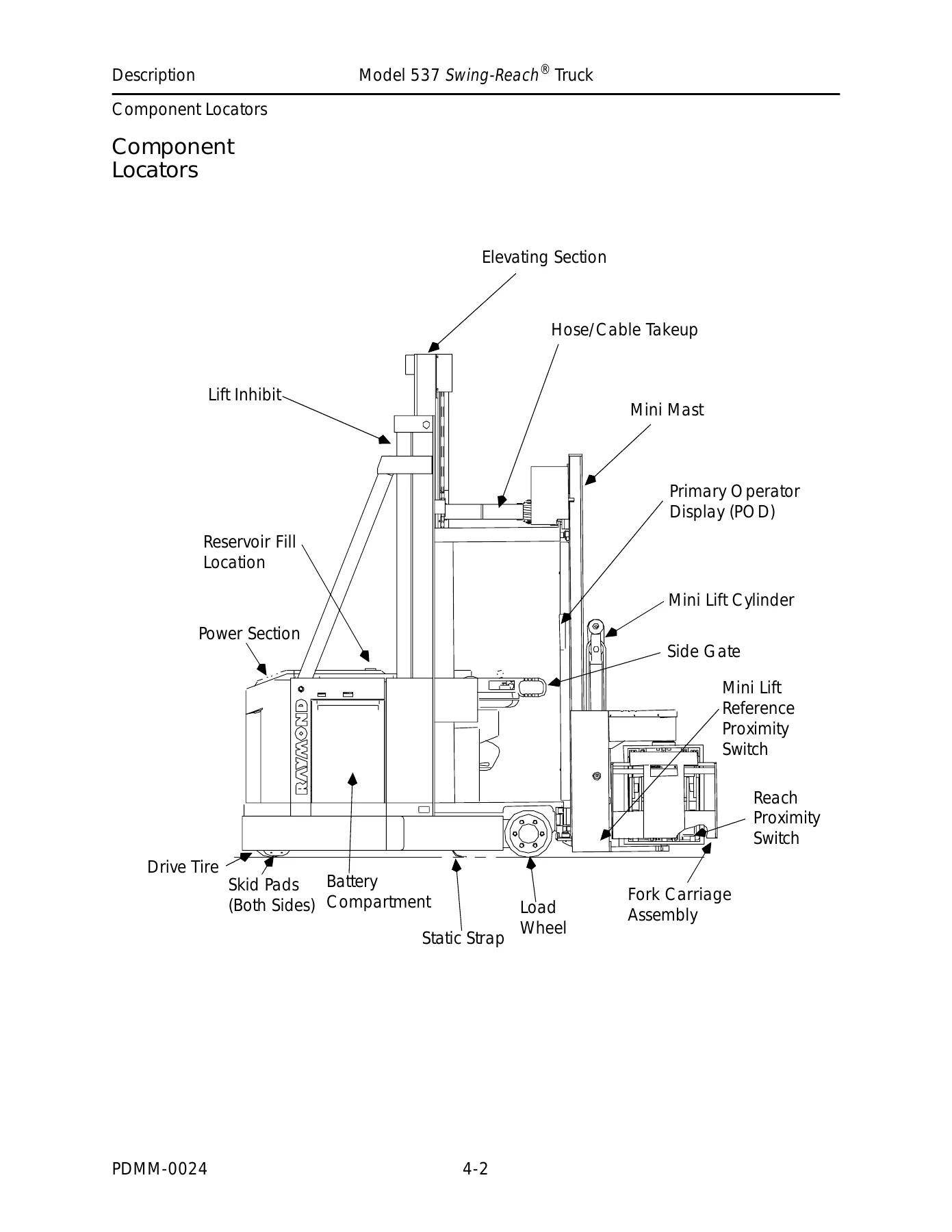
- Description — Component Locators, Truck Specifications, Travel Speed, Acceleration, Stopping Distance, Main Lift, Main Lower, Auxiliary Lift, Auxiliary Lower, Relief Valve Settings, Auxiliary Functions, Fuses
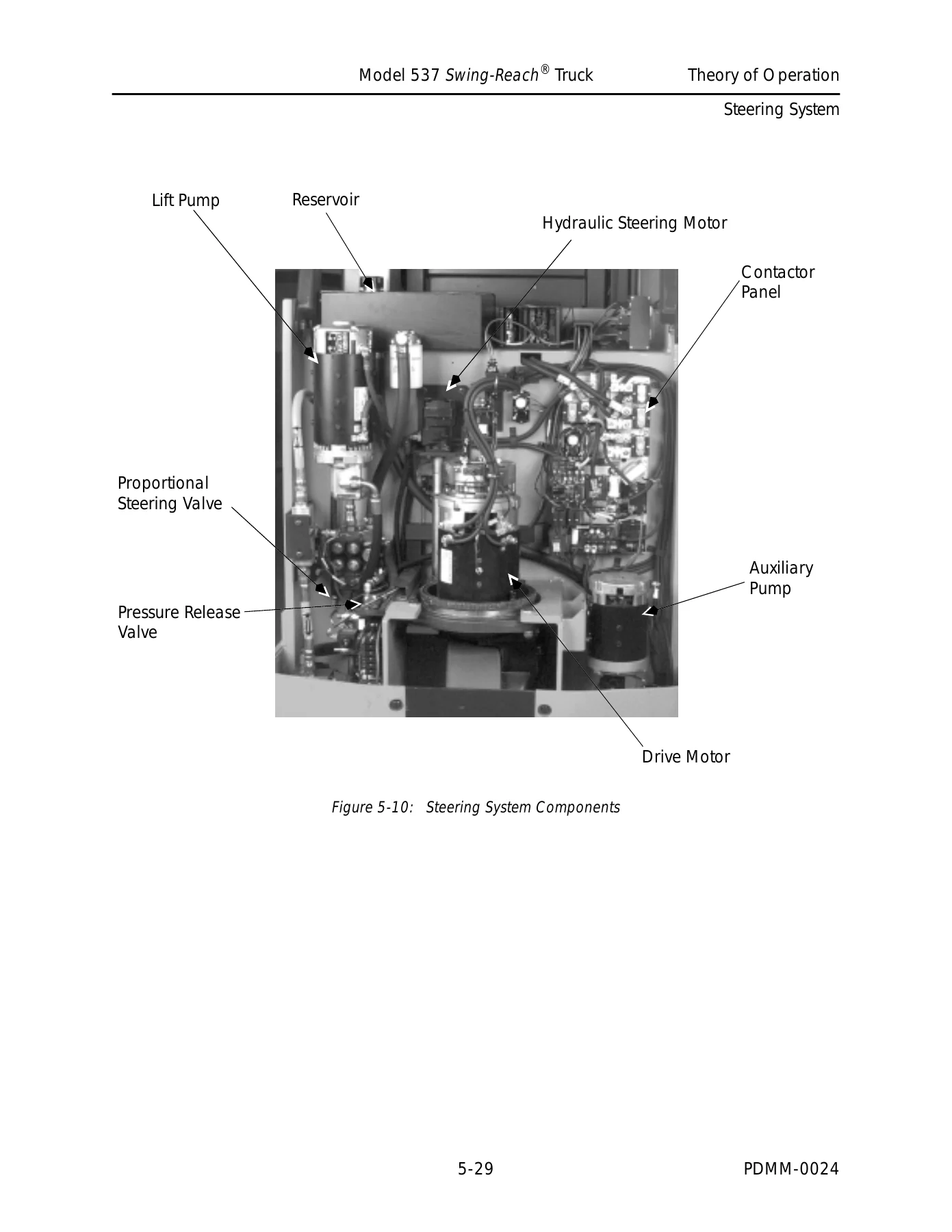
- Theory of Operation — System Architecture, Carriage Manager, Vehicle Manager, intellispeed™ Manager, Primary Operator Display (POD), Communications / BUS+ / BUS–, Lift/Lower Systems, Steering System, Electronic Steering and Wire Guidance, Brake, Traction System, Auxiliary System, Rail Guidance
- Scheduled Maintenance — Daily or Every 8 Hours, Every 30 Days or 200 Hours, Every 180 Days or 1000 Hours, Every 360 Days or 2000 (2160) Hours, Battery Scheduled Maintenance, Motor Scheduled Maintenance, Lubrication and the Raymond Products Lubrication Equivalent Chart
- Troubleshooting — intellidrive2 Troubleshooting, Learn Mode and Troubleshooting, Board and Component Swapping Precautions, Modes of Operation (Run, Program, Learn, Configure, Maintenance), Analog Tests, Output Tests, Input Tests, Cycle Mode, Complete Troubleshooting Code Summary covering system status, performance limiting, power panel, motor and encoder, contactor, communications, height and weight, analog sense, operator controls, guidance, system and load handler codes
- Electronic Steering and Wire Guidance Troubleshooting — Initial Setups, Wire Guidance Test Procedure, Electronic Steering Test Procedure, Setting Position Feedback Potentiometer VR8, Operational Checks, Truck Static and Dynamic Adjustments, System Controller ESTAT Messages, Solenoid Controller Status Messages, Line Driver Adjustment, Optimizing Wire Guidance Performance
- Testing — Analog Tests A00 through A21, Input Tests I00 through I25, Output Tests O00 through O31, Traction System tests including Power Transistor Q1, Chopper Control Module, TM1/TM2 and HCM, Motor testing including brush, armature, field and ground checks
- Maintenance Procedures — Steering (pressure relief, tachometer, position feedback pot), Drive and Brake (motor brush replacement, drive unit replacement and servicing, axle seal replacement, brake adjustment, rotor gap, deadman pedal), Electrical (battery charging, travel pot replacement, power panel), Hydraulic (oil selection, reservoir fluid and filter, bleeding, auxiliary pressure relief), Mast and Load Handler (torque specs, decals, lift chain adjustment, mast lateral adjustment, carriage sliders, cylinder replacement, puck replacement, bearing replacement, cylinder packing, retainer replacement, flow sensor)
- Appendix A — Standard Torque Data for Bolts, Measurement Conversion Table, Decimal Equivalent Chart, O-Rings
- Appendix B — Schematics including electrical lift, lower, mini lift, mini lower, brake process, battery connected, keyswitch on, deadman switches, plugging, traverse, rotate, reach, rail guidance, hydraulic schematic, power distribution, card test connections and electronic steering functional block diagrams
- Appendix C — Inspection Schedule (daily, 30 day, 180 day and 360 day intervals)
- Appendix D — Troubleshooting Code Summary with status, limiting and fault code tables and effect designations
- Index
Read end to end, this manual gives a technician the complete internal picture of the 537: how the Carriage Manager, Vehicle Manager, intellispeed Manager and Primary Operator Display communicate over BUS+/BUS–, how the chopper and H-bridge drive the shunt-wound traction motor, how the auxiliary pump feeds the steering proportional valve and load handler solenoids, and how the wire guidance sensor derives heading angle and distance from wire. Every subsystem is backed by the corresponding electrical and hydraulic schematic, so you can trace a circuit or a hydraulic line rather than guess at it.
Diagnostics and Troubleshooting Code Coverage
A large part of the value in this Raymond 537 maintenance manual sits in the troubleshooting section. Fault codes are broken out by group with the SOD message text, the reason the code is triggered, the system response, and the corrective actions and tests to run. Codes span the power panel (short and open detected in armature and field circuits, temperature sensor faults, current sensor faults), motor and encoder faults, contactor faults for the PC, P, X and 1S contactors, communications faults across the managers, height and weight faults, analog sense faults, operator control faults such as out of range travel and lift pots, guidance faults including wire lost and tracking limits exceeded, system faults such as software mismatch and checksum errors, and load handler faults for reach, traverse and rotate mechanisms.
Every one of those codes points to a specific maintenance test — A-series analog tests, I-series input tests, and O-series output tests — each with its own run procedure and diagnosis-and-repair steps. That structure is what turns a fault code on the Secondary Operator Display into an actual repair instead of a parts swap.
Covered Systems
- Traction system — power transistor Q1, Chopper Control Module, H-Bridge Control Module, field wiring assembly, drive motor encoder, plugging resistor and 1S contactor
- Lift and lower system — main and mini lift cylinders, lift pump and motor, proportional lift/lower solenoid SOL4, load holding solenoids SOL5 and SOL6, lift select solenoids SOL1 and SOL2, flow transducer and pressure transducers
- Auxiliary system — auxiliary pump and motor, load handler select SOL3, traverse proportional solenoids SOL34A/34B, fork control proportional solenoids SOL35A/35B, reach select SOL36, reach cylinders, rotate actuator
- Steering — hydraulic steer motor, proportional steering solenoids, position feedback potentiometer VR8, steering tachometer, steering encoder
- Brake — spring applied, electrically released brake assembly, brake release switch S12, deadman switches S2 and S25
- Wire guidance and rail guidance options — sensor assembly, filter card, processing card, line driver alignment
Why This Raymond 537 Manual Matters
The 537 Swing-Reach is a narrow-aisle turret truck, and the work it does depends on steering, traction, lift and load handler systems all being in adjustment. The specification values in this book — steering relief at 1400 ± 50 PSI, auxiliary relief at 1750 ± 50 PSI, drive unit fluid capacity of 3.5 quarts, reservoir capacity of approximately 7.42 gallons, brake stopping distance of 9 to 13 feet, 24-volt contactor coils pulsed on a 48-volt truck — are the numbers that keep those systems behaving. Maintenance procedures also carry their own torque values, Loctite part numbers, shim specifications, rotor gap clearances, proximity switch gaps and deadman pedal actuation points, so a rebuild can be put back to the condition the truck left the factory in.
Whether you are servicing the brake rotor gap, repacking a main lift cylinder, replacing a mast or carriage puck, shimming the traverse shaft support bushing, adjusting the mini mast proximity switches, or just chasing a Code 99 solenoid controller error, the manual gives you the procedure and the test that isolates the cause.
IMAGES PREVIEW
Instant PDF Delivery
The Raymond Model 537 Swing-Reach Truck Maintenance Manual PDMM-0024 is supplied as an instant-download PDF. There is no shipping and no waiting — the file is available immediately after payment and can be opened on a laptop, tablet or phone in the workshop, printed for the service truck, or kept on a shop computer for quick reference while a truck is on the jack. Search the full document for a fault code, a solenoid number, a torque figure or a component name and get straight to the relevant page.
If you maintain, repair or troubleshoot a Raymond 537 Swing-Reach, this manual is the reference that tells you what the truck is actually doing and what to do about it. Grab the PDF and put the full PDMM-0024 documentation on your device today.
Reviews
There are no reviews yet.