★ TRUSTED BY 321,897+ PROFESSIONALS WORLDWIDE
🏒
Trusted Business
Verified & Licensed
πŸ›‘οΈ
Virus Free Files
100% Safe Downloads
πŸ”’
Secure Payment
SSL Protected
⚑
Instant Delivery
Available Immediately
Sale!

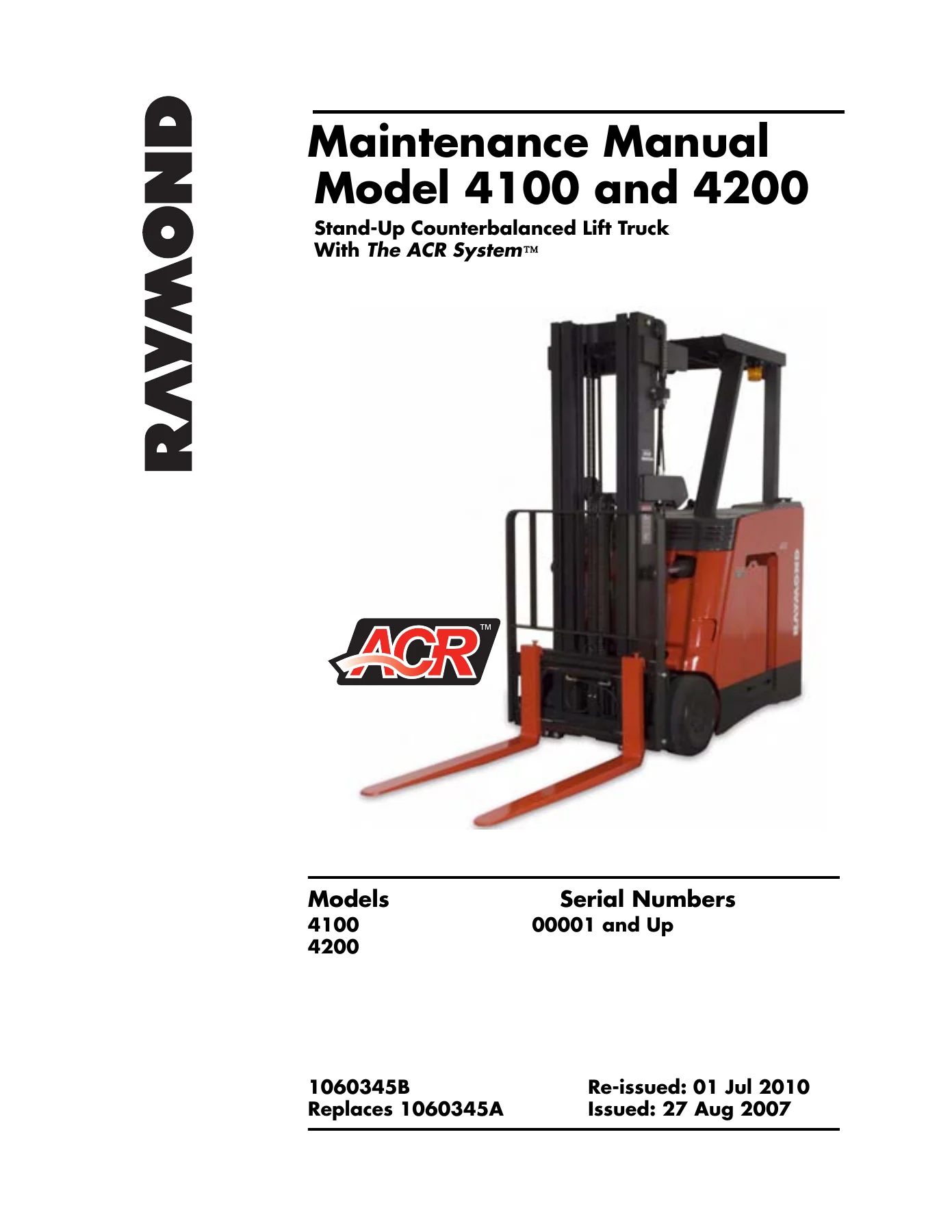
Raymond 4100 & 4200 Stand-Up Counterbalanced Lift Truck Maintenance Manual – ACR System (1060345B)

Original price was: $34.95.Current price is: $19.95.

Complete Raymond maintenance manual for Model 4100 and 4200 stand-up counterbalanced lift trucks with the ACR System. Covers scheduled service, troubleshooting, fault codes, component procedures, hydraulic and electrical theory, torque values and wiring diagrams. 344-page PDF, document 1060345B, serial numbers 00001 and up.

⚑
Instant PDF Download
Available immediately
πŸ’Ύ
Save to Your Device
Download & keep forever
πŸ›‘οΈ
Antivirus Scanned
100% virus-free
🌍
Trusted Worldwide
175,000+ customers

Description

Raymond 4100 & 4200 Stand-Up Counterbalanced Lift Truck Maintenance Manual

This is the full Raymond maintenance manual for the Model 4100 and 4200 stand-up counterbalanced lift trucks equipped with the ACR System. Document number 1060345B, re-issued 01 July 2010, covering serial numbers 00001 and up. It is the same reference a service technician uses in the bay: scheduled maintenance intervals, electrical and hydraulic troubleshooting, fault-code lookups, firmware-based input and output tests, step-by-step component procedures, theory of operation, and the torque, lubricant and conversion charts needed to put everything back together correctly. The manual is written for the DC-lift Model 4100 as well as the AC-lift Model 4200, and it flags model-specific differences where they matter.

File Details

  • Manual type: Maintenance Manual
  • Brand: The Raymond Corporation
  • Models covered: 4100, 4200 (stand-up counterbalanced lift truck with ACR System)
  • Serial numbers: 00001 and Up
  • Document number: 1060345B (original issue 1060345A, 27 Aug 2007)
  • Edition: Re-issue, 01 Jul 2010
  • Language: English
  • Page count: 344
  • File format: PDF

Chapters Covered

  • Section 1 – How to Use This Manual: manual design, abbreviations and symbols, map of the manual
  • Section 2 – Safety: safety definitions, general safety, battery safety, static precautions, jacking safety, towing safety, welding safety
  • Section 3 – Systems Overview: introduction, lift truck specifications, FlashWare, Operator Display, Modes of Operation (Run, Configure, Maintenance), Cold Storage, Storage
  • Section 4 – Scheduled Maintenance: maintenance guidelines, Maintenance Minder tool, Initial 90 Day/250 HD service, Every 180 Days or 500 Deadman Hours, Every 360 Days or 2000 Deadman Hours, contactor tip inspection, lift chains, fork inspection
  • Section 5 – Troubleshooting: electrical troubleshooting, hydraulic troubleshooting, symptom tables for hydraulic functions, drive units, travel functions, electrical symptoms
  • Section 6 – Messages, Codes, and Tests: summary list, messages and codes (2A, 2E, 2G, 2H, 2M, 2T, 2U, 2V, 2W, 2X, 2Y, 42, 43, 4B, 4C, 4F, 4G, 4J, 4K, 59, 5A, 5B, 5F, 5G, 5J, 5M, 5P, 5U, 61, 6D, 7A, 7E, 7F, 7G, 7H, 7M, 7T, 7U, 7V, 7W, 7X, 7Y, 80, 81, 83, 84, 88, 8A, 8F, 8J, 8L, 8P, 8R, 8S, 8T, 8U, 8V, 8W, 8X, 8Z, A0, A2, A3, A4, AG, AH, AL, AP, AT, EC, FE, FG, FH, FN, FT, G2, HA, HE, HF, HG, HH, HM, HT, HU, HV, HW, HX, T0, T3, T4, VC), Digital Input Tests, Analog Tests, Output Tests
  • Section 7 – Component Procedures: steering and controls, steerable wheel assembly, standard control handle, optional control handle, drive units, tire replacement, brakes, battery procedures, power cables, motors, traction motors, lift motor, power amplifiers, wiring and harness connectors, hydraulic components, manifold solenoids and fittings, hydraulic fluid, pressure relief valve, cylinder service, mast service, TF/TT/Quad mast service, hose reeving, lift chains, mast tilt adjustment
  • Section 8 – Theory of Operation: system architecture, systems overview, traction system theory, steering system theory, lift/lower system theory, pinout matrix
  • Appendix A: lubrication specification chart, thread adhesives, sealants and lubricants, component-specific torque chart, standard (ferrous) torque chart, metric torque chart, standard (brass) torque chart, decimal equivalent chart, standard/metric conversions
  • Index
  • Schematics (Publication 1122977A): power distribution diagram, electrical schematic Model 4200 (AC lift), options sheet, electrical schematic legend, electrical schematic Model 4100 (DC lift), hydraulic schematic Model 4200, hydraulic schematic Model 4100, auxiliary function options

What you are getting with this Raymond 4100/4200 maintenance manual is not a generic forklift book. It is a machine-specific service reference written around the ACR System, the dual traction power amplifiers, the lift power amplifier, the Vehicle Manager and the CAN bus that ties them together. Every fault code in Section 6 maps to a test procedure in the same section, and every test procedure points back into the component procedures in Section 7. That interlock is the reason technicians keep this document on the bench rather than the shelf.

Fault Codes, Diagnostics and the Maintenance Minder

The code and message chapter is one of the deepest parts of the manual. It lists each displayed message and fault code with the reason it was triggered, the specific test to run and the corrective action to take. Codes are grouped by system so you can move quickly from a symptom on the Operator Display to the relevant Left or Right Traction Power Amplifier, Lift Power Amplifier, contactor, encoder or sensor circuit. Supporting this are three complete test suites: Digital Input Tests (I00 Deadman through I89 Steer Position Sensor), Analog Tests (A04 Travel Pot through A82 Aux Relief Current) and Output Tests (O00 TPC Contactor through O45 HSA 1 Solenoid). Each test includes a step-by-step Diagnosis and Repair table with meter setting, probe points, expected results and the next action if the reading is correct or incorrect β€” which removes a lot of guesswork from electrical diagnosis.

The manual also covers the Maintenance Minder tool from enabling through resetting, and it walks through Configure Mode and Maintenance Mode parameters: forward and reverse maximum speed, travel and lift acceleration, coast distance, lift cutout point, units for messages, travel alarm behaviour, weight sensor, sideshift enable, and the electronic key. Attachment control is documented with flow-rate setup for push/pull, fork positioner, clamp and clamp-with-roll configurations, including the hydraulic ports each function uses.

Component Procedures and Hydraulic Coverage

Section 7 is where the repairs actually happen. It covers the steerable wheel assembly (removal, disassembly, service, reassembly, chain and sensor adjustment), the standard and optional control handle (return spring, lift/lower and travel potentiometers, sideshift/tilt switch boot, hand soldering guidance), drive unit removal and rebuild including shim calculation, bearing cup installation, pinion and ring gear setup, backlash measurement and contact-pattern checking, brake inspection and rebuild, tire replacement, battery procedures, power cable repair with crimp tool and heat-shrink specifications, DC motor brush inspection and spring tension, AC motor temperature sensor and bearing encoder replacement, traction motor removal and installation, lift motor removal and installation, power amplifier replacement, and the AMP and Molex connector repair procedures.

On the hydraulic side you get the manifold solenoid and fitting torque table, hydraulic fluid selection, system bleeding procedures for both the 4100 and 4200, pressure relief valve measurement and adjustment, main and free lift cylinder service, piston removal, the Quad mast check valve inspection, and full mast service for TF, TT and Quad masts including hose reeving with torque values and tension measurements. The lift chain and fork inspection sections in Section 4 give the wear limits and rejection criteria rather than just a visual check list.

Specifications, Torque and Reference Data

Appendix A closes the manual with a lubrication specification chart listing approved Raymond lubricants and part numbers, a thread adhesive and sealant table keyed to Loctite numbers and colours, a component-specific torque chart, full standard (ferrous), metric and brass torque charts, a decimal equivalent chart and standard/metric conversions. These are the numbers you need at the bench when a fastener, fitting or cylinder retainer goes back on.

Complete PDF Bookmark Tree

Complete Bookmarks

The complete bookmarks in the β€œRaymond 4100 & 4200 Stand-Up Counterbalanced Lift Truck Maintenance Manual – ACR System (1060345B)” are as follows:

Front Coverp. 1
Table of Contentsp. 3
Page Revision Recordp. 5
Document Revision Historyp. 5
Service Bulletin Listp. 6
Product Improvement Notice Listp. 7
Section 1. How to Use This Manualp. 9
Map of the Manualp. 10
Manual Designp. 11
Abbreviations and Symbolsp. 12
Section 2. Safetyp. 15
Safety Definitionsp. 16
General Safetyp. 17
Battery Safetyp. 19
Static Precautionsp. 21
Jacking Safetyp. 22
Jacking the Drive Wheelp. 22
Jacking the Tractorp. 22
Towing Safetyp. 23
Welding Safetyp. 24
Section 3. Systems Overviewp. 25
Introductionp. 26
Lift Truck Specificationsp. 27
Specification Platep. 27
FlashWarep. 28
Overviewp. 28
Requirementsp. 28
Installing FlashWare on PCp. 28
Connecting PC to Truckp. 28
Starting FlashWarep. 28
Truck Setup Screenp. 30
Operator Displayp. 35
Modes of Operationp. 36
Run Modep. 36
Configure Modep. 36
Maintenance Modep. 40
Passwordsp. 42
Attachment Controlp. 44
Cold Storagep. 47
Cold Storage Conditioningp. 47
Storagep. 48
Warrantyp. 48
DC Motorsp. 48
Hydraulic Systemp. 48
Hydraulic Cylindersp. 48
Lift Chainsp. 48
Electronicsp. 48
Section 4. Scheduled Maintenancep. 49
Scheduled Maintenance Guidelinesp. 50
Maintenance Minder β„’ Toolp. 51
Enablingp. 51
Disablingp. 52
Initial 90 Day/250 HD Maintenancep. 53
Every 180 Days or 500 Deadman Hours (HD)p. 54
Every 360 Days or 2000 Deadman Hours (HD)p. 57
Contactor Tip Inspectionp. 58
Lift Chainsp. 59
Inspection and Maintenancep. 59
Fork Inspectionp. 60
Surface Inspectionp. 60
Straightness of Blade and Shankp. 60
Fork Anglep. 60
Fork Tip Heightp. 61
Wearp. 61
Section 5. Troubleshootingp. 65
Electrical Troubleshootingp. 66
Generalp. 66
Shorts to Framep. 66
Fusesp. 68
DC Motorsp. 69
AC Motorsp. 72
Battery State-of-Chargep. 73
Communication Error Code Troubleshootingp. 74
Electrical Connector Locationsp. 75
Hydraulic Troubleshootingp. 79
Auxiliary Hydraulic Pressurep. 79
Pressure Measurementp. 79
Symptom Tables: Hydraulic Functionsp. 80
Intermittent Lift/Lowerp. 80
Lift Functionp. 80
Lower Functionp. 81
Auxiliary Functionsp. 82
Symptom Tables: Drive Unitsp. 83
Oil Leaksp. 83
Drive Wheel Wobblesp. 83
Noisep. 83
Symptom Tables: Travel Functionsp. 84
Slow or Sluggish Accelerationp. 84
Slow Travelp. 84
Sluggish or No Steeringp. 85
Symptom Tables: Electrical Symptomsp. 86
Electrical Motorsp. 86
Operator Displayp. 87
Dead Lift Truckp. 87
Section 6. Messages, Codes, and Testsp. 89
Summary Listp. 90
Messagesp. 90
Codesp. 90
Input Testsp. 92
Analog Testsp. 92
Output Testsp. 93
Messages and Codesp. 95
Digital Input Testsp. 117
Test I00 – Deadman (S2)p. 118
Run test:p. 118
Diagnosis and Repairp. 118
Test I02 – High Speed Limit SW (S11)p. 119
Run test:p. 119
Diagnosis and Repairp. 119
Test I05 – Lift Limit (S12)p. 120
Run test:p. 120
Diagnosis and Repairp. 120
Test I13 – Lift Contactor (DC Lift)p. 121
Run test:p. 121
Diagnosis and Repairp. 121
Test I14 – Steer Contactorp. 122
Run test:p. 122
Diagnosis and Repairp. 122
Test I15 – Horn (S3, SW1)p. 123
Run test:p. 123
Diagnosis and Repairp. 123
Test I19 – Left Traction RPMp. 124
Run test:p. 124
Diagnosis and Repairp. 124
Test I20 – Lift RPM (AC Lift only)p. 125
Run test:p. 125
Diagnosis and Repairp. 125
Test I23 – CAN Communication Testp. 126
Run test:p. 126
Diagnosis and Repairp. 127
Test I65 – Tilt Position SW (S18)p. 128
Run test:p. 128
Diagnosis and Repairp. 128
Test I80 – OCSS – Lowp. 129
Run test:p. 129
Diagnosis and Repairp. 129
Test I81 – OCSS – Highp. 130
Run test:p. 130
Diagnosis and Repairp. 130
Test I82 – Right Traction RPMp. 131
Run test:p. 131
Diagnosis and Repairp. 131
Test I87 – Battery Gatexp. 132
Run test:p. 132
Diagnosis and Repairp. 132
Test I88 – Battery Gate 2p. 133
Run test:p. 133
Diagnosis and Repairp. 133
Test I89 – Steer Position Sensorp. 134
Run test:p. 134
Analog Testsp. 135
Test A04 – Travel Pot (VR1)p. 136
Run test:p. 136
Diagnosis and Repairp. 136
Test A05 – Lift/Lower Pot (VR2)p. 137
Run test:p. 137
Diagnosis and Repairp. 137
Test A08 – Left Traction Motor Tempp. 138
Limitsp. 138
Run test:p. 138
Diagnosis and Repairp. 138
Test A09 – Lift Motor Temp (AC Lift only)p. 139
Limitsp. 139
Run test:p. 139
Diagnosis and Repairp. 139
Test A10 – Left Traction Power Amp Tempp. 140
Limitsp. 140
Run test:p. 140
Diagnosis and Repairp. 140
Test A11 – Left Traction Currentp. 141
Limits:p. 141
Run test:p. 141
Diagnosis and Repairp. 141
Test A13 – Weight Sensor Voltagep. 142
Limitsp. 142
Run test:p. 142
Diagnosis and Repairp. 142
Test A14 – Ext. Supply Sense (12VDC)p. 143
Run test:p. 143
Diagnosis and Repairp. 143
Test A15 – Battery Voltsp. 144
Run test:p. 144
Diagnosis and Repairp. 144
Test A19 – Lift Power Amp Temp (AC Lift only)p. 145
Limitsp. 145
Run test:p. 145
Diagnosis and Repairp. 145
Test A20 – Lift Current (AC Lift only)p. 146
Limitsp. 146
Run test:p. 146
Diagnosis and Repairp. 146
Test A22 – Traction Requestp. 147
Run test:p. 147
Diagnosis and Repairp. 147
Test A23 – Lift Requestp. 148
Run test:p. 148
Diagnosis and Repairp. 148
Test A26 – Pot Supply (5VDC)p. 149
Run test:p. 149
Diagnosis and Repairp. 149
Test A34 – Lift/Lower Current (SOL2)p. 150
Run test:p. 150
Diagnosis and Repairp. 150
Test A36 – Ambient Temperaturep. 151
Run test:p. 151
Diagnosis and Repairp. 151
Test A65 – Right Traction Power Amp Tempp. 152
Limitsp. 152
Run test:p. 152
Diagnosis and Repairp. 152
Test A67 – Right Traction Currentp. 153
Limits:p. 153
Run test:p. 153
Diagnosis and Repairp. 153
Test A68 – Right Traction Motor Tempp. 154
Limitsp. 154
Run test:p. 154
Diagnosis and Repairp. 154
Test A71 – Tilt Down (S7)p. 155
Run test:p. 155
Diagnosis and Repairp. 155
Test A72 – Tilt Up (S6)p. 156
Run test:p. 156
Diagnosis and Repairp. 156
Test A72 – Tilt Up/Down (SW4) (Optional Handle)p. 157
Run test:p. 157
Diagnosis and Repairp. 157
Test A73 – Sideshift Right (S9)p. 158
Run test:p. 158
Diagnosis and Repairp. 158
Test A74 – Sideshift Left (S8)p. 159
Run test:p. 159
Diagnosis and Repairp. 159
Test A74 – Sideshift Left/Right (SW4) (Optional Handle)p. 160
Run test:p. 160
Diagnosis and Repairp. 160
Test A75 – Attach Fcn 1 (S4)p. 161
Run test:p. 161
Diagnosis and Repairp. 161
Test A75 – Attach Fcn 1 (SW3) (Optional Handle)p. 162
Run test:p. 162
Diagnosis and Repairp. 162
Test A76 – Attach Fcn 2 (S5)p. 163
Run test:p. 163
Diagnosis and Repairp. 163
Test A76 – Attach Fcn 2 (SW2) (Optional Handle)p. 164
Run test:p. 164
Diagnosis and Repairp. 164
Test A77 – EPO (S21)p. 165
Run test:p. 165
Diagnosis and Repairp. 165
Test A80 – Lift Relief Current (SOL3)p. 166
Run test:p. 166
Diagnosis and Repairp. 166
Test A81 – Priority Bypass Current (SOL4)p. 167
Run test:p. 167
Diagnosis and Repairp. 167
Test A82 – Aux. Relief Current (SOL5)p. 168
Run test:p. 168
Diagnosis and Repairp. 168
Output Testsp. 169
Test O00 – TPC Contactorp. 170
Run test:p. 170
Diagnosis and Repairp. 170
Test O01 – Steer Contactor (STR)p. 171
Run test:p. 171
Diagnosis and Repairp. 171
Test O02 – Lift Contactor (LPC)p. 172
Run test:p. 172
Diagnosis and Repairp. 172
Test O04 – Aux. Direction Solenoid (SOL6)p. 173
Run test:p. 173
Diagnosis and Repairp. 173
Test O07 – Tilt Solenoid (SOL10)p. 174
Run test:p. 174
Diagnosis and Repairp. 174
Test O08 – Sideshift Solenoid (SOL9L, SOL9R)p. 175
Run test:p. 175
Diagnosis and Repairp. 175
Test O09 – Lift Relief Solenoid (SOL3)p. 176
Run test:p. 176
Diagnosis and Repairp. 176
Test O11 – Load Hold Solenoid (SOL1)p. 177
Run test:p. 177
Diagnosis and Repairp. 177
Test O12 – Lift/Lower Solenoid (SOL2)p. 178
Run test:p. 178
Diagnosis and Repairp. 178
Test O18 – Hornp. 179
Run test:p. 179
Diagnosis and Repairp. 179
Test O19 – Ramp Sounderp. 180
Run test:p. 180
Diagnosis and Repairp. 180
Test O20 – Travel Alarmp. 181
Run test:p. 181
Diagnosis and Repairp. 181
Test O23 – Toggle Amplifier Fanp. 182
Run test:p. 182
Diagnosis and Repairp. 182
Test O28 – Ramp Lift Motor (AC Lift)p. 183
Run test:p. 183
Diagnosis and Repairp. 183
Test O29 – Ramp Traction Motorsp. 184
Run test:p. 184
Diagnosis and Repairp. 184
Test O30 – Electric Brakesp. 185
Run test:p. 185
Diagnosis and Repairp. 185
Test O32 – Toggle Relay Enablep. 186
Run test:p. 186
Diagnosis and Repairp. 186
Test O36 – Priority Bypass Solenoid (SOL4)p. 187
Run test:p. 187
Diagnosis and Repairp. 187
Test O37 – Aux. Relief Solenoid (SOL5)p. 188
Run test:p. 188
Diagnosis and Repairp. 188
Test O45 – HSA 1 Solenoid (SOL7C, SOL7R)p. 189
Run test:p. 189
Diagnosis and Repairp. 189
Section 7. Component Proceduresp. 191
List of Component Proceduresp. 192
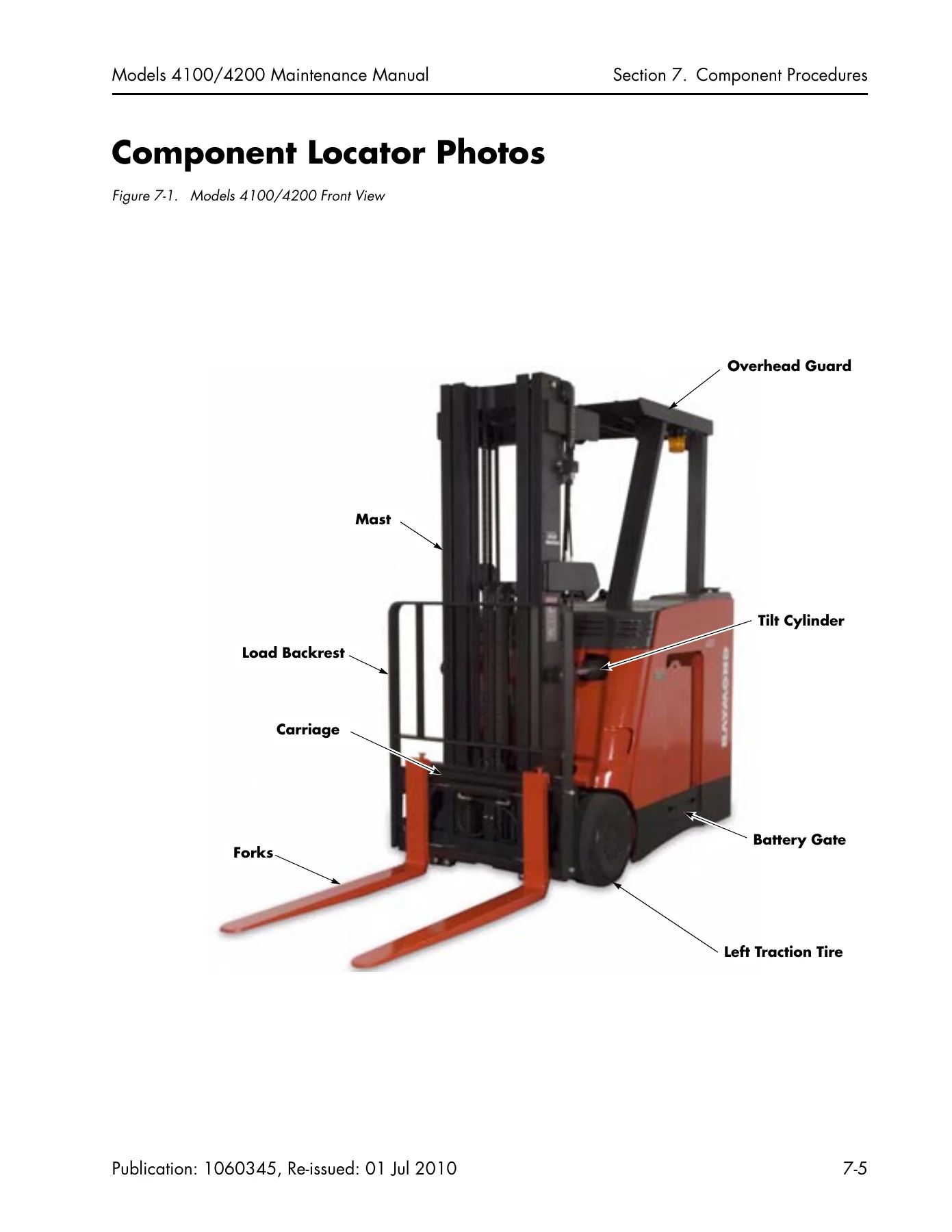
Component Locator Photosp. 195
Steering and Controlsp. 199
Steerable Wheel Assemblyp. 200
Removalp. 200
Installationp. 202
Disassemblyp. 203
Servicep. 204
Reassemblyp. 204
Control Handle – Standardp. 205
Removalp. 205
Handle Disassemblyp. 205
Handle Assemblyp. 205
Installationp. 206
Inspectionp. 206
Hand Soldering Proceduresp. 206
Control Handle – Optionalp. 208
Return Spring Replacementp. 208
Handle Removalp. 208
Disassemblyp. 208
Lift/Lower Potentiometer (VR2) Replacementp. 208
Travel Potentiometer (VR1) Replacementp. 210
Sideshift/Tilt Switch Rubber Boot Replacementp. 210
Assemblyp. 210
Installationp. 211
Drive and Brakep. 213
Drive Unitsp. 214
Removalp. 214
Installationp. 215
Adding Oilp. 215
Repairp. 216
Tire Replacementp. 227
Brakesp. 228
Inspectionp. 228
Removalp. 228
Disassemblyp. 228
Assemblyp. 228
Installationp. 229
Electrical Componentsp. 231
Battery Proceduresp. 232
Battery Connector/Cablesp. 232
Power Cablesp. 234
Power Cable Repairp. 234
Motorsp. 236
Generalp. 236
DC Motor Servicep. 236
AC Motor Servicep. 238
Traction Motorsp. 241
Removalp. 241
Installationp. 241
Lift Motorp. 243
Removalp. 243
Installationp. 243
Power Amplifiersp. 244
Removalp. 244
Installationp. 244
Wiring and Harness Connectorsp. 245
General Connector Repair Proceduresp. 245
Molex Connectorsp. 245
AMP Water-Resistant Connectorsp. 246
AMP Harness/Traction Power Amplifier Connectorp. 250
Hydraulic Componentsp. 253
Manifold Solenoids, Fittings, and Attachmentsp. 254
Hydraulic Fluidp. 258
Fluid Levelp. 258
Selecting Hydraulic Fluid Typep. 258
Bleeding the Hydraulic Systemp. 258
Pressure Relief Valvep. 260
Measuring System Pressurep. 260
Adjusting Pressurep. 260
Cylinder Servicep. 261
Main or Free Lift Cylinders – Model 4200p. 261
Piston Removalp. 261
Quad Mast Check Valve Inspectionp. 262
Mastp. 263
Mast Servicep. 264
Upright Inspection – Model 4200p. 264
Mast Skewing – Model 4200p. 264
Mast Removalp. 264
Mast Installationp. 265
TF and TT Mast Service – Model 4200p. 267
TF Mast Disassemblyp. 267
TF Mast Reassemblyp. 267
TF Mast Main Lift Cylinder Removalp. 267
TF Mast Main Lift Cylinder Installationp. 268
TT Mast Disassemblyp. 268
TT Mast Reassemblyp. 268
TT Mast Main Lift Cylinder Removalp. 269
TT Mast Main Lift Cylinder Installationp. 269
TT Mast Free Lift Cylinder Removalp. 269
TT Mast Free Lift Cylinder Installationp. 270
TT Mast Free Lift Cylinder Supply Hosep. 270
Carriage – Model 4200 TF and TT Mastsp. 271
Carriage Removalp. 271
Carriage Installationp. 271
Hose Reevingp. 272
Internal Reeving – Model 4200 TF Mastp. 272
Internal Reeving – Model 4200 TT Mastp. 274
Quad Mast Servicep. 277
Mast Inspectionp. 277
Disassemblyp. 277
Reassemblyp. 279
Carriagep. 282
Cylinder Removal and Installationp. 282
Reevingp. 283
Lift Chainsp. 288
Adjusting Lift Chains – Model 4100p. 288
Adjusting Lift Chains – Model 4200p. 288
Model 4200 TT Mast – 2 in. to 3 in. Lowered Height Conversionp. 289
Mast Tilt Adjustmentp. 290
Adjusting the Mast Tilt Position Switchp. 290
Section 8. Theory of Operationp. 291
System Architecturep. 292
Systems Overviewp. 293
Intelligent Devicesp. 293
Non-intelligent Devicesp. 294
Hydraulic Devicesp. 294
Traction System Theoryp. 296
Key ONp. 296
Deadman Pedal Depressedp. 296
Travel Theoryp. 296
Steering System Theoryp. 298
Lift/Lower System Theoryp. 299
Model 4100p. 299
Model 4200p. 300
Auxiliary Functionsp. 300
Pinout Matrixp. 303
Section A. Appendixp. 317
Lubrication Specification Chartp. 318
Thread Adhesives, Sealants, and Lubricantsp. 319
Component Specific Torque Chartp. 320
Torque Chart – Standard (Ferrous)p. 321
Torque Chart – Metricp. 322
Torque Chart – Standard (Brass)p. 323
Decimal Equivalent Chartp. 324
Standard/Metric Conversionsp. 326
Section I. Indexp. 327
Schematicsp. 334
Figure 1-1. Power Distribution Diagramp. 335
Figure 1-2. Electrical Schematic – Model 4200 (AC Lift) – Sheet 1 of 4p. 336
Figure 1-3. Electrical Schematic – Options – Sheet 2 of 4p. 337
Figure 1-4. Electrical Schematic Legend – Sheet 3 of 4p. 338
Figure 1-5. Electrical Schematic – Model 4100 (DC Lift) – Sheet 4 of 4p. 340
Figure 1-6. Hydraulic Schematic – Model 4200 – AC Lift (Sheet 1 of 3)p. 341
Figure 1-7. Hydraulic Schematic – Model 4100 – DC Lift (Sheet 2 of 3p. 342
Figure 1-8. Hydraulic Schematic – Auxiliary Function Options (Sheet 3 of 3)p. 343

Who This Manual Is For

This Raymond 4100 4200 maintenance manual is aimed at the technician or fleet maintainer who already works on stand-up counterbalanced trucks and needs the factory procedure, the fault code lookup and the torque and lubrication values in one place. It is equally useful to a shop that has just taken a 4100 or 4200 into its fleet and wants the maintenance schedule, the diagnostic tests and the component procedures on hand without chasing individual pages. If you service the ACR System trucks regularly, the wiring and hydraulic schematics included in the schematics publication make this a complete bench reference for the model.

IMAGES PREVIEW

Raymond 4100 & 4200 Stand-Up Counterbalanced Lift Truck Maintenance Manual - ACR System (1060345B) β€” PDF page 1 preview
Raymond 4100 & 4200 Stand-Up Counterbalanced Lift Truck Maintenance Manual - ACR System (1060345B) β€” PDF page 195 preview
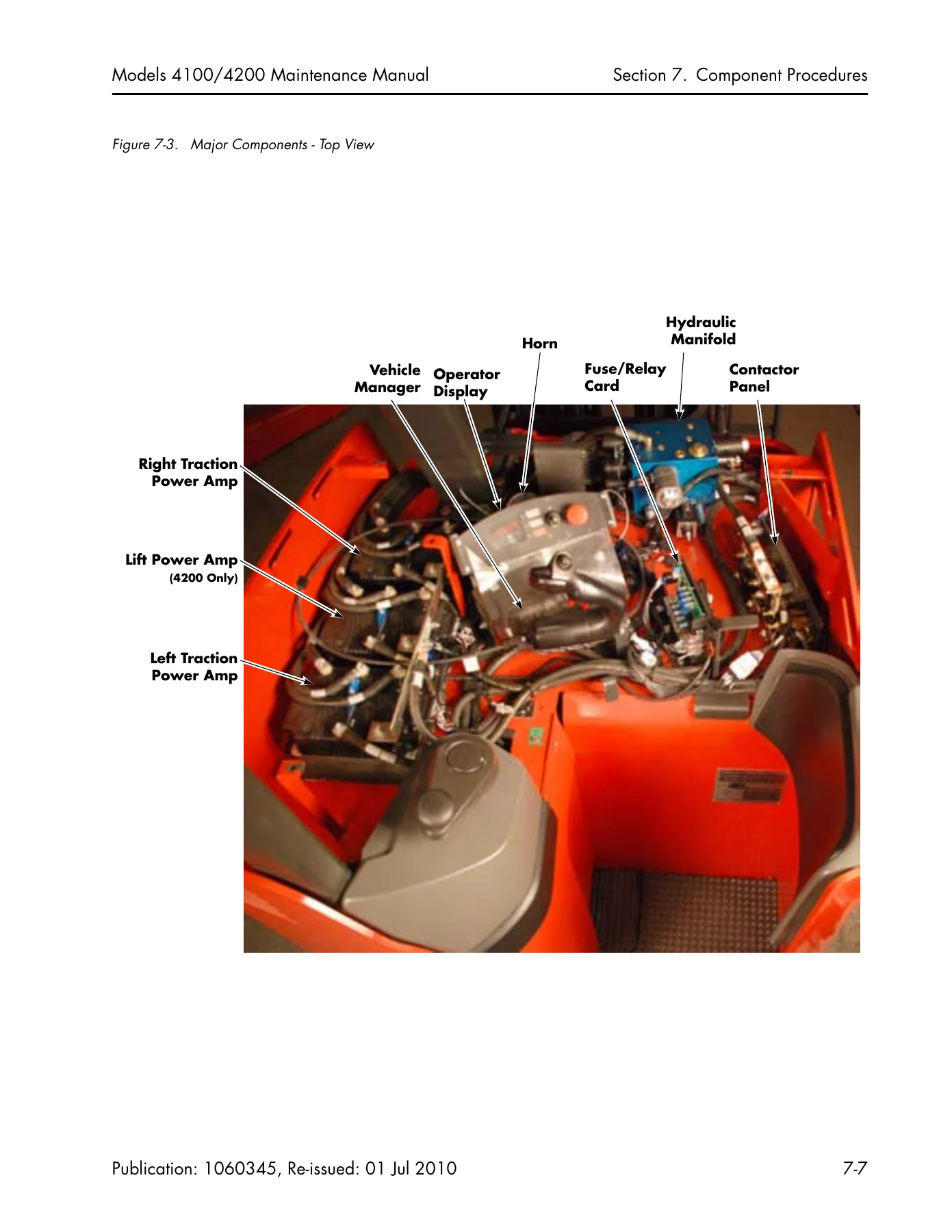
Raymond 4100 & 4200 Stand-Up Counterbalanced Lift Truck Maintenance Manual - ACR System (1060345B) β€” PDF page 197 preview

Instant PDF Delivery

The Raymond 4100 & 4200 Stand-Up Counterbalanced Lift Truck Maintenance Manual is delivered as an instant-download PDF. There is no shipping, no waiting and no physical book to keep track of. Open it on a laptop, tablet or phone in the shop, print the fault-code tables or torque charts you need for the job, and keep the rest on file. Because it is a PDF, you can search by code, connector identifier or component name and jump straight to the section you need β€” handy when a truck is down and the code on the display is the only clue you have.
Reviews

There are no reviews yet.

Be the first to review “Raymond 4100 & 4200 Stand-Up Counterbalanced Lift Truck Maintenance Manual – ACR System (1060345B)”

What Our Customers Say

β˜…β˜…β˜…β˜…β˜… Live reviews from customers
Loading customer reviews...
0
    0
    Your Cart
    Your cart is emptyReturn to Shop
    πŸ›’
    Recently Purchased
    πŸ•’ verified order