
Nichiyu FBRF14 FBRF16 FBRF20 75 Series Electric Lift Truck Troubleshooting Manual – PDF
Original price was: $39.95.$23.95Current price is: $23.95.
Electrical troubleshooting, self-diagnosis, adjustment and wiring manual for Nichiyu 75 series electric lift trucks FBRF14, FBRF16 and FBRF20, covering the monitor display, MPU travel/hydraulic board, EPS controller, error codes, I/O checks and full system wiring diagrams.
Description
The Nichiyu FBRF14, FBRF16 and FBRF20 75 Series Electric Lift Truck Troubleshooting Manual is the electrical and electronic diagnostic guide for these SICOS-AC controlled reach trucks. It moves a technician from what the operator sees on the dashboard through to the board, sensor, potentiometer or harness that caused the fault, using the truck’s own self-diagnosis system, error history memory and I/O data as the starting point for every repair.
File Details
- Manual type: Electric lift truck troubleshooting manual
- Brand: Nichiyu (Nippon Yusoki Co., Ltd.)
- Models covered: FBRF14, FBRF16, FBRF20 – 75 series
- Language: English
- File format: PDF
- Page count: 110 pages
- Issued by: Nippon Yusoki Co., Ltd., Overseas Division
- First printing: May 2010
Chapters Covered
- Basic Setting – explanation of the monitor display; indicator panel; indication of display; function of display; various kinds of mode selection; explanation of the MPU board; basic control board construction; MPU board (travel/hydraulic board); EPS controller (EPS/DSP board); MPU board setting; EPS controller setting; adjustment standards list
- Various Setting and Adjustment – model setting; display monitor symbol (icon) check and setting; steering setting check and adjustment; switch back (plugging/regenerative) braking force adjustment; regenerative braking force check and adjustment; hydraulic speed setting and adjustment; optional function check and setting; display of voltage, current and temperature; current detector check; accelerator potentiometer adjustment; brake potentiometer adjustment; I/O check; hydraulic lever (joystick) adjustment and check; error history memory 1 and 2; battery voltage calibration; turning speed reduction setting; AOS setting (option); clearing the error history memory
- Troubleshooting – self diagnosis function; display; error messages and display conditions; servicing data; electrical failures when no error code is displayed
- Other Electric Check and Adjustment – hour meter working check; chassis insulation check; display brightness check and adjustment; OIS (Operation Interlock System) working check; valve electric current adjustment; safety circuit for control (contactor tripping) check; foot switch working check; neutral safety function check; lift interrupt working check; cooling fan working check; battery tray interlock check; auto power off check
- Operation Procedures for Truck with AOS – joystick operation; automatic lifting stop operation; A/B rack switching; lifting height limit mode switching; storing the stop position; stop (emergency stop) operation
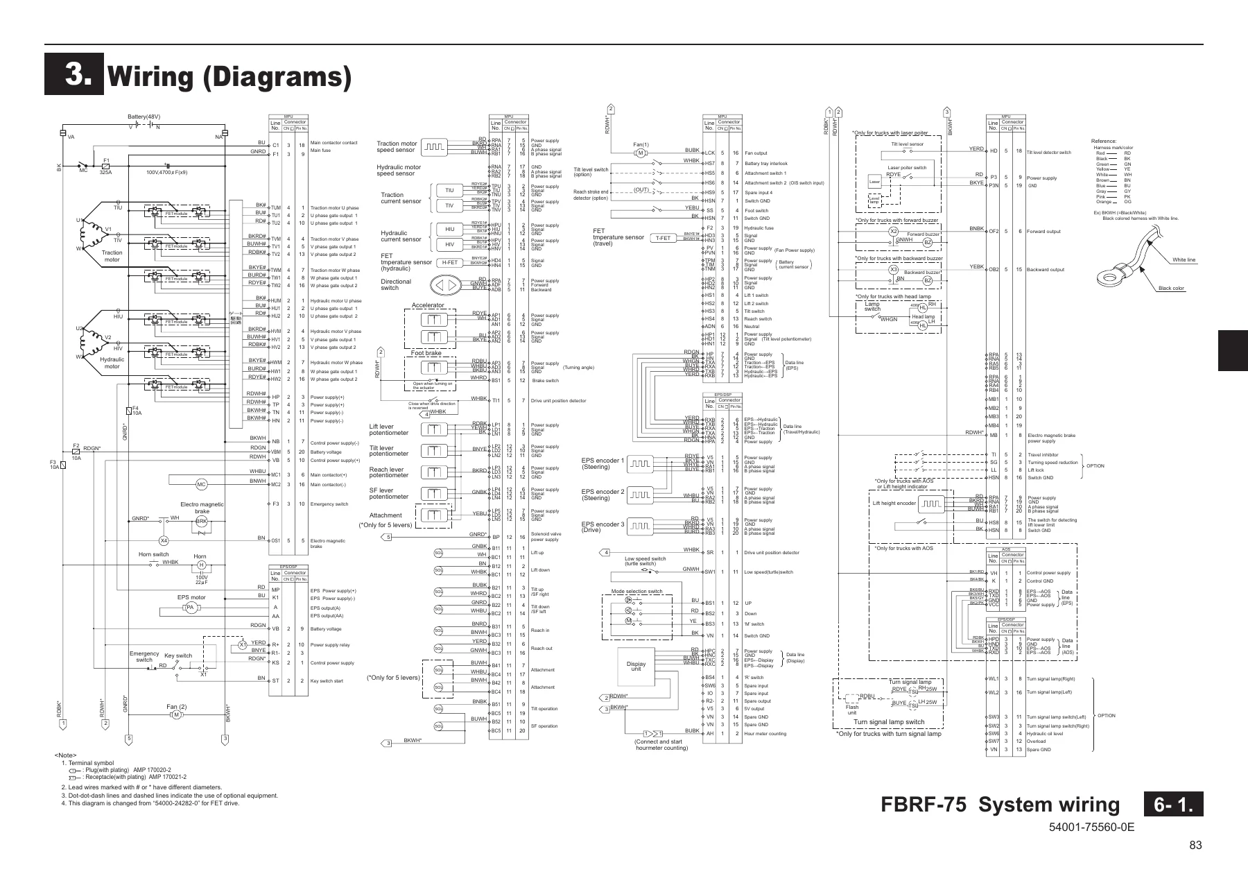
- Wiring (Diagrams) – system wiring; body wiring; body harnesses; floor harness; switch harness; main controller; controller wiring; controller harness; lead wire for main controller; wiring PS; harness PS; lever panel wiring; lever panel harness; lever harness for 4 spools (5-way piping); chime/buzzer wiring; light wiring; head lamp wiring; head guard harness
Read as a whole, this troubleshooting manual is a complete electrical service path for the 75 series truck rather than a scattered collection of checks. The first chapter establishes what the display is telling you and how the MPU board and EPS controller are configured for the specific truck in front of you, including the rotary switch model selection and the proportional valve current volumes. The second chapter turns that into hands-on adjustment work: setting the accelerator and brake potentiometers against the correct I/O data windows, confirming the steering mode, tuning plugging and regenerative braking force, and checking joystick neutral values on the lift, tilt, reach and side shift levers. The third and fourth chapters then hand you the diagnostic method itself, including what to do when the truck is dead but no error number appears on screen.
Monitor, Error Codes and Self-Diagnosis
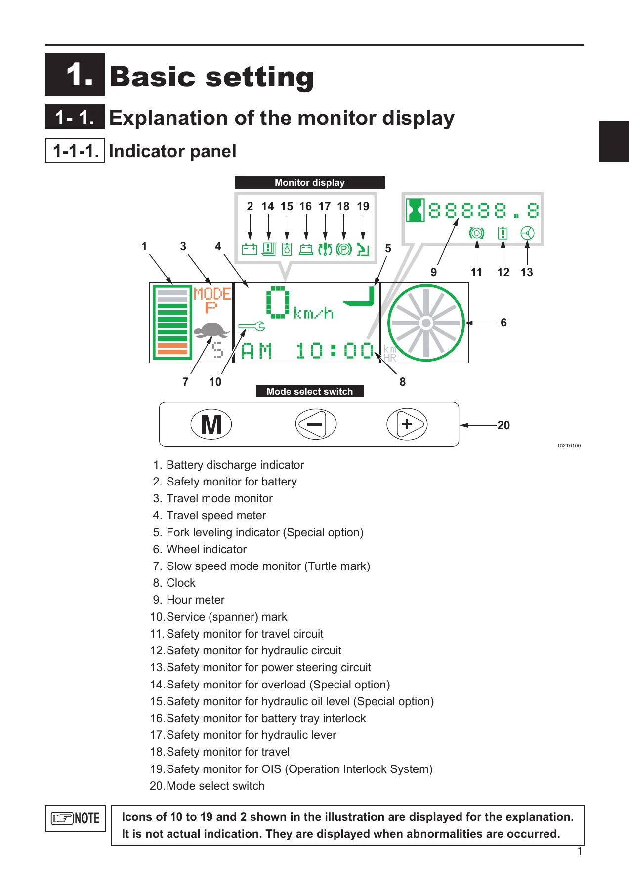
A large part of this manual exists because the truck diagnoses itself, and the documentation explains both sides of that conversation. You get the full description of the indicator panel layout, the battery discharge indicator behaviour as capacity falls, the lift interrupt that halves lift speed when two red segments remain, travel mode and slow speed mode indications, the wheel indicator, hour meter and the various service and safety monitor icons. Every monitor symbol is tied to a condition, so a flashing spanner, travel, hydraulic, steering, battery, hydraulic lever, OIS or parking brake icon tells you which system has been interlocked before you open a single connector.
From there the manual lists the error messages and the exact detection conditions behind them, with the likely causes and the CPU that logs them. The covered codes run across the whole machine: A01 main contactor, B10 main fuse, B11 through B13 traction U, V and W-phase FET, B14 traction motor current sensor, B15 accelerator, B16 directional switch, B17 foot brake, C21 through C23 hydraulic U, V and W-phase FET, C24 hydraulic motor current sensor, D30 EPS limit switch, D31 and D33 EPS encoders, D32 EPS transistor, D34 EPS current, E40 solenoid valve, E41 lever potentiometer, E42 fork-height detection encoder, G61 and G62 current errors, G63 and G64 voltage errors, G65 main board and FET temperature error, G68 display communication error, G69 control power error, plus the W05 through W13 warnings for overload, hydraulic oil level, battery charge, neutral safety and OIS. For each one the manual gives you the reference values you need to prove or eliminate the circuit, and the servicing data section collects the coil voltages, coil resistances, sensor output voltages and FET continuity checks in one place.
The error history memory function is covered in two parts, letting you read back the most recently detected faults and the previously stored ones, including how many times each occurred and the total key-on hours at detection. That alone makes intermittent electrical faults on these trucks far faster to pin down, because you can see what happened on the last shift instead of waiting for the fault to reappear.
Boards, Controllers and Wiring Diagrams
The control architecture is documented board by board. The MPU board (travel/hydraulic board, type PBC109-XX) and the EPS controller (EPS/DSP board, type PB103-XXX) are shown with their connectors, LED normal-condition indicators, rotary switch functions and volume adjustments, and the manual explains the setting changes that must be made after either board is replaced. The I/O check tables then let you watch live hexadecimal data from the travel, hydraulic and EPS CPUs as you operate each switch and lever, so you can confirm a foot switch, brake switch, directional switch, battery interlock, lever potentiometer or EPS encoder is actually reaching the controller.
The wiring chapter reproduces the system wiring, body wiring, controller wiring and harness layouts, including the body harnesses for standard and CS/FCS trucks, the floor and switch harnesses, the lever panel and 4-spool lever harnesses, and the accessory circuits for chime, buzzer, lights and head lamps. For anyone chasing a broken conductor or a corroded connector, these diagrams plus the connector pin layouts are the difference between a guess and a diagnosis.
Put This Troubleshooting Manual to Work
With this manual on hand you can read and clear the truck’s fault memory, interpret every monitor symbol and error number the display can produce, verify accelerator and brake potentiometer ranges, set hydraulic proportional valve currents to specification, confirm the OIS, foot switch, neutral safety, battery tray interlock and auto power off functions are behaving, calibrate battery voltage after a controller replacement, and work through the wiring diagrams to isolate an open or shorted circuit. That covers the work that actually stops a 75 series truck: a contactor that will not pull in, a FET module that trips, a dead display, a machine that will not travel or lift, and the intermittent faults that only show up in the error history.
Having the manufacturer’s own detection conditions and reference values matters because these are AC controller machines, and a wrong assumption about a sensor output or a coil resistance sends you replacing parts that were never faulty. The adjustment standards list, the servicing data and the I/O check tables together give you numbers to measure against rather than opinions to argue about.
IMAGES PREVIEW
Delivery is instant. This Nichiyu FBRF14, FBRF16 and FBRF20 75 series troubleshooting manual is supplied as a downloadable PDF, so there is no shipping and no waiting – open it on a laptop, tablet or phone in the workshop, print the pages you need for the job, and keep the rest of the file for the next fault.
Reviews
There are no reviews yet.