★ TRUSTED BY 321,897+ PROFESSIONALS WORLDWIDE
🏢
Trusted Business
Verified & Licensed
🛡️
Virus Free Files
100% Safe Downloads
🔒
Secure Payment
SSL Protected
⚡
Instant Delivery
Available Immediately
Sale!

Raymond 7530 Reach-Fork Truck Maintenance Manual 1252763/001C – Serial 0000101 and Up

Original price was: $39.95.Current price is: $24.95.

Complete Raymond 7530 Reach-Fork Truck Maintenance Manual (Publication 1252763/001C, revised 17 Jan 2023) covering serial numbers 0000101 and up. Includes scheduled maintenance, troubleshooting, fault codes, electrical and hydraulic tests, component procedures, theory of operation, torque charts, and full schematics.

⚡
Instant PDF Download
Available immediately
💾
Save to Your Device
Download & keep forever
🛡️
Antivirus Scanned
100% virus-free
🌍
Trusted Worldwide
175,000+ customers

Description

Raymond 7530 Reach-Fork Truck Maintenance Manual – Publication 1252763/001C

This is the complete Raymond 7530 Reach-Fork Truck Maintenance Manual, publication number 1252763/001C, revised 17 January 2023. It applies to lift trucks with serial numbers 0000101 and Up. The manual is written for trained service personnel and covers the full range of maintenance, troubleshooting, diagnostic testing, and component repair procedures for the 7530 Reach-Fork Truck.

File Details

  • Manual Type: Maintenance Manual
  • Brand: Raymond
  • Model: 7530 Reach-Fork Truck
  • Serial Numbers: 0000101 and Up
  • Publication Number: 1252763/001C
  • Revision Date: 17 January 2023
  • Language: English
  • File Format: PDF

Chapters Covered

  • How to Use This Manual — Manual Design, Interactive Electronic Technical Manuals, Abbreviations and Symbols
  • Safety — Safety Definitions, General Safety, Battery Safety, Static Precautions, Jacking Safety, Welding Safety
  • Systems Overview — Lift Truck Specifications, Model Designations, General Information, Lift Truck Installation, FlashWare, Evolution Display, Passwords, Modes of Operation
  • Scheduled Maintenance — Maintenance Guidelines, Maintenance Minder, Initial 90 Day/250 Deadman Hours Maintenance, Every 180 Days or 500 HD Maintenance, Every 360 Days or 2000 HD Maintenance, Lubrication Points, Contactor Tip Inspection, Chain Maintenance, Fork Inspection
  • Troubleshooting — Electrical Troubleshooting, Troubleshooting Power Amplifier Error Codes, Troubleshooting Steering Fault Codes (G Series), Troubleshooting Energy Power System Faults, Hydraulic Troubleshooting Guidelines, Symptom Tables for Hydraulic Functions, Travel Functions, and Electrical Symptoms
  • Messages, Codes, and Tests — Power Amp LED Diagnostics, Messages and Codes Summary, Analog Tests, Input Tests, Output Tests
  • Component Procedures — Component Locator Photos, Special Tools, Decals, Tags and Plates, Baselegs, Load Wheel Replacement, Steering and Controls, Drive and Brake, Electrical Components, Battery Procedures, Wiring and Harness Connectors, Power Cables, Motors, Steer Amplifier, Cold Storage Conditioning, Hydraulic Components, Hydraulic Cylinders, Mast, Chain, Hose, Cable
  • Theory of Operation — Traction System Functional Operation, Hydraulic System Functional Operation, Brake Operation, Cold Storage, Pinout Matrix
  • Appendix — Lubrication Specification Chart, Thread Adhesives Sealants and Lubricants, Component Specific Service/Torque Chart, Torque Charts for Hydraulic Fittings, Straight Thread Face Seal O-Rings, Standard and Metric Ferrous and Brass, Thread Forming Screws, Decimal Equivalent Chart, Standard/Metric Conversions
  • Schematics — Electrical Schematics (12 sheets), Hydraulic Schematics (2 sheets)

What This Raymond 7530 Maintenance Manual Provides

The Raymond 7530 Reach-Fork Truck Maintenance Manual is the definitive service reference for this model. It opens with a full systems overview covering lift truck specifications, model and serial number designations, configuration codes, battery specifications, fluid capacities, and installation requirements. The scheduled maintenance section lays out service intervals at 90 days/250 deadman hours, 180 days/500 HD, and 360 days/2000 HD, with detailed task tables for the drive unit, hydraulic reservoir, mast, power amplifiers, brakes, contactors, control handles, cylinders, deadman pedal, drive unit, electrical cables, fans, forks, frame and baselegs, hardware, horn, hydraulic hoses, lift chains, motors, overhead guard, power amplifiers, static straps, steering, switches, ventilation slots, warning decals, warning lights, and wheels and tires.

The troubleshooting section is built around practical symptom-based diagnosis. It covers electrical troubleshooting with shorts-to-frame testing, battery state-of-charge behavior and lift cutout adjustment, fuse and relay diagnostics, connector locator charts, and circuit card connector identification. Dedicated tables address power amplifier error codes with sub-codes for traction, lift, and auxiliary amplifiers, steering fault codes (G Series), and Energy Power System faults for both Power Source Limiting and Public Standard Interface options. Hydraulic troubleshooting guidelines are followed by symptom tables for auxiliary functions, reach and retract, lift and lower, and travel functions.

Fault Codes and Diagnostic Tests

A major portion of this 7530 Reach-Fork maintenance manual is the Messages, Codes, and Tests section. It documents the power amplifier LED diagnostics and then provides an extensive messages and codes summary covering dozens of fault codes — from Code 1D (APA Overheated) through Code VC (CAN Stuck In Reset State). Each code entry gives the title and reason, the test to run, and notes or corrective action. The manual then provides Analog Tests, Input Tests, and Output Tests with step-by-step diagnosis and repair tables. These tests cover throttle potentiometer voltage, lift/lower potentiometer voltage, traction motor temperature, lift motor temperature, TPA temperature, traction motor current, APA temperature, pressure sensor voltage, +12VDC and +5VDC power supplies, battery voltage, auxiliary motor temperature and current, LPA temperature, lift motor current, traction throttle request, lift throttle request, secondary traction throttle, lower current, brake armature, ambient air temperature, steer amp current, analog reference voltage, handle heater reference, emergency power off switch, travel and lift pot learn values, EPS current/voltage/temperature, H2O sense, BSM communication, oil temperature, max EPS discharge and regen charge, deadman switch, nested switch, reach and retract switches, tilt up/down switches, sideshift left/right switches, steering fuse, horn switch, aux motor encoder, traction motor RPM, lift motor RPM, CAN bus test, steer limit switch, steer motor encoder, height encoders for main and free lift, secondary horn, steer tiller encoders, neutral pulses, customer interlocks, security start switch, OCSS upper and lower beams, battery gate switches, lift height, height reference prox sensor, and dozens of output tests for contactors, solenoids, relays, fans, motors, brake coil, handle heater, ThermaKit, customer output, and laser on/off.

Complete PDF Bookmark Tree

Complete Bookmarks

The complete bookmarks in the “Raymond 7530 Reach-Fork Truck Maintenance Manual 1252763/001C – Serial 0000101 and Up” are as follows:

Visual Table of Contentsp. 1
Cover Pagep. 6
Document Revision Historyp. 10
Service Information Listp. 11
Section 1. How to Use This Manualp. 12
Manual Designp. 13
Interactive Electronic Technical Manualsp. 14
Abbreviations and Symbolsp. 15
Section 2. Safetyp. 18
Safety Definitionsp. 19
General Safetyp. 20
Battery Safetyp. 23
Static Precautionsp. 26
Jacking Safetyp. 27
Jacking the Lift Truckp. 27
Welding Safetyp. 29
Section 3. Systems Overviewp. 30
Systems Overview Introductionp. 31
Lift Truck Specificationsp. 32
Load Capacityp. 32
Model Designationsp. 33
Mast Seriesp. 33
Serial Numberp. 33
General Informationp. 34
Battery Specificationsp. 34
Fluid Capacitiesp. 34
Lift Truck Installationp. 35
FlashWarep. 36
FlashWare Overviewp. 36
Installing FlashWare on a Windows Compatible Devicep. 36
Connecting FlashWare to Lift Truckp. 36
Starting FlashWarep. 37
Evolution Displayp. 38
Evolution Display Overviewp. 38
Updating Evolution Display Softwarep. 39
Evolution Display Dashboardp. 40
Passwordsp. 42
Passwordp. 42
Superwordp. 42
Electronic Key (optional)p. 42
Entering a Password, Superword, or Electronic Keyp. 42
To set or change a Password, Superword, or Electronic Keyp. 42
Modes of Operationp. 43
Mode of Operation Overviewp. 43
Run Modep. 43
Program Modep. 45
Service Menup. 54
Section 4. Scheduled Maintenancep. 56
Maintenance Guidelinesp. 57
Maintenance Minder ™p. 58
Configuring/Resetting Maintenance Minderp. 58
Initial 90 Day/250 Deadman Hours (HD) Maintenancep. 59
Every 180 Days or 500 HD Maintenancep. 60
Every 360 Days or 2000 HD Maintenancep. 63
Lubrication Pointsp. 64
Contactor Tip Inspectionp. 65
Chain Maintenancep. 66
Lift Chain Inspectionp. 66
Condition-Cause Chartp. 66
Fork Inspectionp. 67
Fork Surface Inspectionp. 67
Straightness of Blade and Shankp. 67
Fork Anglep. 67
Fork Tip Heightp. 68
Positioning Locks (if applicable)p. 68
Fork Wearp. 69
Section 5. Troubleshootingp. 72
Electrical Troubleshootingp. 73
Generalp. 73
Shorts to Framep. 73
Battery State-of-Chargep. 76
Fusesp. 77
Electrical Connectionsp. 78
Fuse/Relay Card Troubleshootingp. 83
DC Motorsp. 85
AC Motorsp. 87
Troubleshooting Power Amplifier Error Codesp. 88
Troubleshooting Steering Fault Codes (G Series)p. 89
Code Shown After Deadman Pedal Is Pressedp. 89
Intermittent Steering Related Error Codesp. 89
Troubleshooting Energy Power System Faultsp. 90
Troubleshooting Power Source Limit Faultsp. 90
Diagnosis and Repairp. 90
Troubleshooting Public Standard Interfacep. 91
Diagnosis and Repair – Code UAp. 91
Diagnosis and Repair – Code UBp. 91
Hydraulic Troubleshooting Guidelinesp. 92
Symptom Tables: Hydraulic Functionsp. 93
Auxiliary Functionsp. 93
Lift/Lower Systemp. 96
Symptom Tables: Travel Functionsp. 98
Slow or Sluggish Accelerationp. 98
Slow Travelp. 98
Oil Leaksp. 99
Drive Wheel Wobblesp. 99
Drive Unit Noisep. 99
Steering Bindsp. 100
Symptom Tables: Electrical Symptomsp. 101
Motor Overheatingp. 101
Display is Darkp. 101
Section 6. Messages, Codes, and Testsp. 102
Power Amp LED Diagnosticsp. 103
Messagesp. 104
Codesp. 104
Messages and Codesp. 108
Messagesp. 108
Codesp. 109
Analog Testsp. 134
Input Testsp. 134
Output Testsp. 135
Analog Testsp. 136
Test A04 – Throttle Pot Voltagep. 137
Run Testp. 137
Diagnosis and Repairp. 137
Test A05 – Lift/Lower Pot Voltagep. 138
Run Testp. 138
Diagnosis and Repairp. 138
Test A08 – Traction Motor Temperaturep. 139
Limitsp. 139
Run Testp. 139
Diagnosis and Repairp. 139
Test A09 – Lift Motor Temperaturep. 140
Limitsp. 140
Run Testp. 140
Diagnosis and Repairp. 140
Test A10 – TPA Temperaturep. 141
Limitsp. 141
Run Testp. 141
Diagnosis and Repairp. 141
Test A11 – Traction Motor Currentp. 142
Limitsp. 142
Run Testp. 142
Diagnosis and Repairp. 142
Test A12 – APA Temperaturep. 143
Limitsp. 143
Run Testp. 143
Diagnosis and Repairp. 143
Test A13 – Pressure Sensor Voltagep. 144
Run Testp. 144
Diagnosis and Repairp. 144
Test A14 – +12VDC Power Supplyp. 145
Run Testp. 145
Diagnosis and Repairp. 145
Test A15 – Battery Voltagep. 146
Run Testp. 146
Diagnosis and Repairp. 146
Test A16 – Aux Motor Temperaturep. 147
Limitsp. 147
Run Testp. 147
Diagnosis and Repairp. 147
Test A18 – Aux Motor Currentp. 148
Limitsp. 148
Run Testp. 148
Diagnosis and Repairp. 148
Test A19 – LPA Temperaturep. 149
Limitsp. 149
Run Testp. 149
Diagnosis and Repairp. 149
Test A20 – Lift Motor Currentp. 150
Limitsp. 150
Run Testp. 150
Diagnosis and Repairp. 150
Test A22 – Traction Throttle Requestp. 151
Run Testp. 151
Diagnosis and Repairp. 151
Test A23 – Lift Throttle Requestp. 152
Run Testp. 152
Diagnosis and Repairp. 152
Test A26 – +5VDC Power Supplyp. 153
Run Testp. 153
Diagnosis and Repairp. 153
Test A29 – 2nd Traction Throttle Pot Voltage (optional)p. 154
Run Testp. 154
Diagnosis and Repairp. 154
Test A30 – 2nd Traction Throttle Request (optional)p. 155
Run Testp. 155
Diagnosis and Repairp. 155
Test A34 – Lower Currentp. 156
Run Testp. 156
Diagnosis and Repairp. 156
Test A35 – Brake Armaturep. 157
Run Testp. 157
Diagnosis and Repairp. 157
Test A36 – Ambient Air Temp Sensor (optional)p. 158
Run Testp. 158
Diagnosis and Repairp. 158
Test A37 – Steer Amp Currentp. 159
Run Testp. 159
Diagnosis and Repairp. 159
Test A39 – Analog Reference Voltagep. 160
Run Testp. 160
Diagnosis and Repairp. 160
Test A40 – Handle Heater Reference (optional)p. 161
Run Testp. 161
Diagnosis and Repairp. 161
Test A41 – Emergency Power Off Switchp. 162
Run Testp. 162
Diagnosis and Repairp. 162
Test A42 – Travel Pot Learn Valuep. 163
Test A43 – Lift Pot Learn Valuep. 164
Test A96 – EPS Current Actual (PSI Only)p. 165
Test A97 – EPS Voltage Actual (PSI Only)p. 166
Test A98 – EPS Temp (PSI Only)p. 167
Test A99 – H2O Sensep. 168
Test A100 – BSM Communicationp. 169
Test A102 – Oil Temperaturep. 170
Limitsp. 170
Run Testp. 170
Diagnosis and Repairp. 170
Test A103 – Max EPS Discharge (PSI Only)p. 171
Test A104 – Max EPS Regen Charge (PSI Only)p. 172
Input Testsp. 174
Test I00 – Deadman Switchp. 175
Run Testp. 175
Diagnosis and Repairp. 175
Test I01 – Nested Switch (optional)p. 176
Run Testp. 176
Diagnosis and Repairp. 176
Test I06 – Reach Switchp. 177
Run Testp. 177
Diagnosis and Repairp. 177
Test I07 – Retract Switchp. 178
Run Testp. 178
Diagnosis and Repairp. 178
Test I08 – Tilt Up Switchp. 179
Run Testp. 179
Diagnosis and Repairp. 179
Test I09 – Tilt Down Switchp. 180
Run Testp. 180
Diagnosis and Repairp. 180
Test I10 – Sideshift Right Switchp. 181
Run Testp. 181
Diagnosis and Repairp. 181
Test I11 – Sideshift Left Switchp. 182
Run Testp. 182
Diagnosis and Repairp. 182
Test I14 – Steering Fusep. 183
Run Testp. 183
Diagnosis and Repairp. 183
Test I15 – Horn Switchp. 184
Run Testp. 184
Diagnosis and Repairp. 184
Test I18 – Aux Motor Encoderp. 185
Run Testp. 185
Diagnosis and Repairp. 185
Test I19 – Traction Motor RPMp. 186
Run Testp. 186
Diagnosis and Repairp. 186
Test I20 – Lift Motor RPMp. 187
Run Testp. 187
Diagnosis and Repairp. 187
Test I23 – CAN Bus Testp. 188
Run Testp. 188
Diagnosis and Repairp. 188
Test I24 – Steer Limit Switchp. 191
Run Testp. 191
Diagnosis and Repairp. 191
Test I25 – Steer Motor Encoderp. 192
Run Testp. 192
Diagnosis and Repairp. 192
Test I26 – Height Encoder – Main Liftp. 193
Run Testp. 193
Diagnosis and Repairp. 193
Test I27 – Secondary Horn (optional)p. 194
Run Testp. 194
Diagnosis and Repairp. 194
Test I33 – Steer Tiller Encoder 1 Connect Detectp. 195
Run Testp. 195
Diagnosis and Repairp. 195
Test I34 – Steer Tiller Encoder 2 Connect Detectp. 196
Run Testp. 196
Diagnosis and Repairp. 196
Test I35 – Steer Tiller Encoder 1 – Channels A & Bp. 197
Run Testp. 197
Diagnosis and Repairp. 197
Test I36 – Steer Tiller Encoder 2 – Channels A & Bp. 198
Run Testp. 198
Diagnosis and Repairp. 198
Test I39 – Neutral Pulsesp. 199
Run Testp. 199
Diagnosis and Repairp. 199
Test I40 – Customer Interlock 1p. 200
Run Testp. 200
Diagnosis and Repairp. 200
Test I43 – Customer Interlock 2p. 201
Run Testp. 201
Diagnosis and Repairp. 201
Test I60 – Security Start Switch (optional)p. 202
Run Testp. 202
Diagnosis and Repairp. 202
Test I64 – Height Encoder – Free Liftp. 203
Run Testp. 203
Diagnosis and Repairp. 203
Test I80 – OCSS Upper Beam (optional)p. 204
Run Testp. 204
Diagnosis and Repairp. 204
Test I81 – OCSS Lower Beam (optional)p. 206
Run Testp. 206
Diagnosis and Repairp. 206
Test I82 – OCSS Count (optional)p. 208
Test I83 – Left Battery Gate Switch (optional)p. 209
Run Testp. 209
Diagnosis and Repairp. 209
Test I84 – Right Battery Gate Switch (optional)p. 210
Run Testp. 210
Diagnosis and Repairp. 210
Test I86 – Lift Heightp. 211
Run Testp. 211
Test I120 – Height Reference Prox Sensorp. 212
Run Testp. 212
Diagnosis and Repairp. 212
Output Testsp. 214
Test O00 – Toggle MPC Contactorp. 215
Run Testp. 215
Diagnosis and Repairp. 216
Test O01 – Toggle STR Contactorp. 217
Run Testp. 217
Diagnosis and Repairp. 217
Test O04 – Toggle AUX1 Directional Solenoidp. 218
Run Testp. 218
Diagnosis and Repairp. 218
Test O05 – Toggle AUX2 Directional Solenoidp. 219
Run Testp. 219
Diagnosis and Repairp. 219
Test O06 – Toggle Reach Solenoidp. 220
Run Testp. 220
Diagnosis and Repairp. 220
Test O07 – Toggle Tilt Solenoidp. 221
Run Testp. 221
Diagnosis and Repairp. 221
Test O08 – Toggle Sideshift Solenoidp. 222
Run Testp. 222
Diagnosis and Repairp. 222
Test O11 – Toggle Load Hold Solenoidp. 223
Run Testp. 223
Diagnosis and Repairp. 223
Test O12 – Ramp Proportional Lower Solenoidp. 224
Test O18 – Toggle Hornp. 225
Run Testp. 225
Diagnosis and Repairp. 225
Test O19 – Audible Alarmp. 226
Run Testp. 226
Test O20 – Travel Alarm (optional)p. 227
Run Testp. 227
Diagnosis and Repairp. 227
Test O21 – Degrees from Centerp. 228
Run Testp. 228
Diagnosis and Repairp. 228
Test O23 – Toggle Fansp. 229
Run Testp. 229
Diagnosis and Repairp. 229
Test O27 – Ramp Aux Motorp. 230
Run Testp. 230
Diagnosis and Repairp. 230
Test O28 – Ramp Lift Motorp. 231
Run Testp. 231
Diagnosis and Repairp. 231
Test O29 – Ramp Traction Motorp. 232
Run Testp. 232
Diagnosis and Repairp. 232
Test O30 – Toggle Brake Coilp. 233
Test O32 – Toggle Relays K1, K2, K3, and K4p. 234
Run Testp. 234
Diagnosis and Repairp. 234
Test O33 – Handle Heater (optional)p. 235
Run Testp. 235
Diagnosis and Repairp. 235
Test O35 – ThermaKit Enable (optional)p. 236
Run Testp. 236
Diagnosis and Repairp. 236
Test O61 – Customer Output (optional)p. 237
Run Testp. 237
Diagnosis and Repairp. 237
Test O64 – Laser ON/OFF (optional)p. 238
Run Testp. 238
Diagnosis and Repairp. 238
Section 7. Component Proceduresp. 240
List of Component Proceduresp. 241
Component Locator Photosp. 244
Tractor, Standard Lift, Fore/Aft Stancep. 245
Tractor Deck, Fore/Aft Stancep. 246
Tractor Deck, Dockstancep. 246
Standard Carriage, Operator View (Mast Guard removed for clarity)p. 247
Underside Componentsp. 248
Special Tools, Decals, and Chassisp. 250
Special Toolsp. 251
Decals, Tags, and Platesp. 252
Baselegsp. 258
Baseleg Removalp. 258
Baseleg Installationp. 259
Load Wheel Replacementp. 260
Load Wheel Removalp. 260
Load Wheel Disassemblyp. 260
Load Wheel Reassemblyp. 260
Load Wheel Installationp. 260
Steering and Controlsp. 262
Steer Tiller Encoderp. 263
Steer Tiller Encoder (Fore/Aft) Removalp. 263
Steer Tiller Encoder (Fore/Aft) Installationp. 263
Steer Tiller Encoder (Dockstance) Removalp. 263
Steer Tiller Encoder (Dockstance) Installationp. 264
Steer Limit Switch (S11)p. 265
Steer Limit Switch Vertical Gap Adjustmentp. 265
Steer Limit Switch Lateral Adjustmentp. 265
Steer Limit Switch Adjustment – Auto Steer Centerp. 265
Steerable Casterp. 266
Steerable Caster Initial Adjustmentp. 266
Steerable Caster Height Adjustmentp. 267
Steering Linkagep. 269
Control Handlep. 270
Primary Control Handle – Fore/Aft Stancep. 270
Dockstance Control Handlep. 276
Secondary Control Handle – Fore/Aft Stancep. 281
Drive and Brakep. 286
Drive Unitp. 287
Required Toolsp. 288
Drive Unit Troubleshootingp. 290
Radial Ring Inspectionp. 290
Drive Unit Removalp. 290
Drive Unit Disassemblyp. 291
Drive Unit Assemblyp. 295
Brakep. 306
Brake Inspectionp. 306
Brake Removalp. 306
Brake Pad Replacementp. 306
Brake Coil Replacementp. 307
Brake Installationp. 307
Deadman Pedalp. 309
Inertial Dampenerp. 310
Inertial Dampener Removalp. 310
Inertial Dampener Installation and Adjustmentp. 312
Electrical Componentsp. 314
Battery Proceduresp. 315
Battery Connector/Cablesp. 315
Battery Exterior Cleaningp. 316
Testing, Charging, and Maintenancep. 317
Battery Storage and Maintenance Chargingp. 317
Battery State-of-Chargep. 317
Wiring and Harness Connectorsp. 318
General Repair Proceduresp. 318
Molex Connectorsp. 319
Universal Mate-N-Lok Connectorsp. 320
AMPSEAL Connectorp. 323
Power Cablesp. 325
Power Cable Repairp. 325
Motorsp. 327
Power Cable Terminalsp. 327
DC Motor Troubleshootingp. 327
AC Motor Troubleshootingp. 327
DC Motor Servicep. 327
Polishing the Commutatorp. 332
AC Motor Servicep. 332
Steer Amplifierp. 334
Steer Amplifier Removalp. 334
Steer Amplifier Installationp. 334
Cold Storage Conditioningp. 335
Cold Storage Componentsp. 335
Cold Storage Lubricantsp. 335
Cold Storage Sealing Treatmentp. 335
Cold Storage Corrosion Inhibitor Coatingp. 335
Cold Storage Condensation Drip Guardp. 335
Hydraulic Componentsp. 336
Hydraulic System Bleedingp. 337
Hydraulic Bleeding Procedurep. 337
Hydraulic Filtersp. 338
Reservoir Filterp. 338
Aux Manifold Filterp. 338
Lift Pump Replacementp. 339
Lift Pump Primingp. 340
Lift Relief Pressure Adjustmentp. 341
Manual Lowering of Fork Carriagep. 342
Auxiliary Pump/Motor Servicep. 343
Aux Pump Primingp. 344
Auxiliary Relief Pressure Adjustmentp. 345
Lift/Lower Manifoldp. 346
Aux Manifoldp. 347
Standard Reach Manifoldp. 348
Standard Reach Manifold Removalp. 349
Standard Reach Manifold Installationp. 349
Deep-Reach ® Manifoldp. 350
Deep-Reach Manifold Removalp. 351
Deep-Reach Manifold Installationp. 351
Tilt/Sideshift Manifoldp. 352
Tilt/Sideshift Manifold Removalp. 352
Tilt/Sideshift Manifold Installationp. 352
Hydraulic Components, Cylindersp. 354
Free Lift Cylinderp. 355
Left Side Free Lift Cylinder Removalp. 355
Left Side Free Lift Cylinder Installationp. 355
Right Side Free Lift Cylinder Removalp. 355
Right Side Free Lift Cylinder Installationp. 356
Free Lift Cylinder Seal Repackingp. 357
Free Lift Cylinder Disassemblyp. 357
Free Lift Cylinder Reassemblyp. 357
Main Lift Cylinderp. 359
Left Side Main Lift Cylinder Removalp. 359
Left Side Main Lift Cylinder Installationp. 359
Right Side Main Lift Cylinder Removalp. 360
Right Side Main Lift Cylinder Installationp. 360
Main Lift Cylinder Seal Repackingp. 361
Main Lift Cylinder Disassemblyp. 361
Main Lift Cylinder Reassemblyp. 361
Lift Cylinder Lowering Cushionp. 362
Main Lift Cylinders Disassemblyp. 362
Main Lift Cylinders Reassemblyp. 362
Free Lift Cylinders Disassemblyp. 362
Free Lift Cylinders Reassemblyp. 363
Reach Cylinderp. 364
Reach Cylinder Removalp. 364
Reach Cylinder Disassemblyp. 364
Reach Cylinder Reassemblyp. 365
Reach Cylinder Installationp. 365
Reach Cylinder Adjustmentp. 365
Tilt Cylinderp. 368
Tilt Cylinder Removalp. 368
Tilt Cylinder Disassemblyp. 368
Tilt Cylinder Reassemblyp. 369
Tilt Cylinder Installationp. 369
Sideshift Cylinderp. 371
Sideshift Cylinder Removalp. 371
Sideshift Cylinder Disassemblyp. 371
Sideshift Cylinder Reassemblyp. 371
Sideshift Cylinder Installationp. 371
Main Lift Flow Limiterp. 372
Main Lift Flow Limiter Removalp. 372
Main Lift Flow Limiter Installationp. 372
Free Lift Flow Limiterp. 373
Free Lift Flow Limiter Removalp. 373
Free Lift Flow Limiter Installationp. 373
Mast, Chain, Hose, Cablep. 374
Carriage Bearingsp. 375
Carriage Bearing Removalp. 375
Carriage Bearing Installationp. 375
Carriage Bearing Adjustmentp. 375
Mast Shimmingp. 376
Mast and Bearing Inspectionp. 376
Shimming Procedurep. 377
Carriagep. 378
Carriage Removalp. 378
Carriage Installationp. 378
Chain Anchorsp. 379
Main Lift Chain Anchors Preparation for Removalp. 379
Upper Main Lift Chain Anchor Removalp. 379
Upper Main Lift Chain Anchor Installationp. 380
Lower Main Lift Chain Anchor Removalp. 380
Lower Main Lift Chain Anchor Installationp. 380
Upper Free Lift Chain Anchor Removalp. 380
Upper Free Lift Chain Anchor Installationp. 381
Lift Chainsp. 382
Main Lift Chain Removalp. 382
Main Lift Chain Installationp. 382
Free Lift Chain Removalp. 383
Free Lift Chain Installationp. 383
Height Encoder Beltsp. 384
Main Lift Height Encoder Belt Removalp. 384
Main Lift Height Encoder Belt Installationp. 384
Free Lift Height Encoder Belt Removalp. 386
Free Lift Height Encoder Belt Installationp. 386
Height Reference Switchp. 387
Height Reference Switch Adjustmentp. 387
OTM Hose and Cable Replacementp. 388
OTM Hose and Cable Removalp. 389
OTM Hose and Cable Installationp. 390
Free Lift Feed Hosep. 394
Free Lift Feed Hose Removalp. 394
Free Lift Feed Hose Installationp. 394
Mast – Complete Disassemblyp. 395
Separation of Tractor and Mastp. 395
Hose/Cable, Free Lift Cylinder, and Carriage Removalp. 395
Main Lift Chain Removalp. 397
Separation of Telescopicsp. 398
Mast – Complete Assemblyp. 401
Assembling and Shimming Outer Telescopic to Main Framep. 401
Assembling and Shimming Inner Telescopic to Outer Telescopicp. 402
Main Lift Chain Installationp. 404
Shimming Carriage to Inner Telescopicp. 406
Carriage, Free Lift Cylinder, and Hose/Cable Installationp. 406
Mating Mast to Tractorp. 409
Back Tilt and Lateral Lean Inspectionp. 411
Section 8. Theory of Operationp. 414
Traction System Functional Operationp. 415
Battery Connectedp. 415
Key Turned ONp. 415
Deadman Pedal Pressedp. 416
Steeringp. 417
Travel Requestp. 417
Hydraulic System Functional Operationp. 419
Hydraulic System Componentsp. 419
Main Lift Systemp. 419
Auxiliary Systemp. 420
Theory of Lift/Aux Functionsp. 421
Brake Operationp. 424
Overviewp. 424
Brake Releasep. 424
Brake Applicationp. 424
Brake Release Screwsp. 424
Cold Storagep. 425
Pinout Matrixp. 426
Section A. Appendixp. 446
Lubrication Specification Chartp. 447
Thread Adhesives, Sealants, and Lubricantsp. 448
Component Specific Service/Torque Chartp. 449
Torque Chart – Hydraulic Fittingsp. 452
Torque Chart – Straight Thread Face Seal O-Ringsp. 453
Torque Chart – Standard (Ferrous)p. 454
Torque Chart – Metric (Ferrous)p. 455
Torque Chart – Standard (Brass)p. 456
Torque Chart – Metric (Brass)p. 457
Torque Chart – Thread Forming Screwsp. 458
Decimal Equivalent Chartp. 459
Standard/Metric Conversionsp. 461
Section I. Indexp. 462
Schematicsp. 474
Figure 1-1. Power Distribution Diagramp. 475
Figure 1-2. Electrical Schematic – Blank Page (Sheet 1of 12)p. 476
Figure 1-3. Electrical Schematic – Blank Page (Sheet 2 of 12)p. 477
Figure 1-4. Electrical Schematic (Sheet 3 of 12)p. 478
Figure 1-5. Electrical Schematic – Evolution Display (Sheet 4 of 12)p. 479
Figure 1-6. Electrical Schematic – Options (Sheet 5 of 12)p. 480
Figure 1-7. Electrical Schematic – Options (con’t) (Sheet 6 of 12)p. 481
Figure 1-8. Electrical Schematic – Options (con’t) (Sheet 7 of 12)p. 482
Figure 1-9. Electrical Schematic – Options (con’t) (Sheet 8 of 12)p. 483
Figure 1-10. Electrical Schematic – Blank Page (Sheet 9 of 12)p. 484
Figure 1-11. Electrical Schematic – Blank Page (Sheet 10 of 12)p. 485
Figure 1-12. Electrical Schematic – Legend (Sheet 11 of 12)p. 486
Figure 1-13. Electrical Schematic – Blank Page (Sheet 12 of 12)p. 487
Figure 1-14. Hydraulic Schematic (Sheet 1 of 2)p. 488
Figure 1-15. Hydraulic Schematic – Options (Sheet 2 of 2)p. 489

Component Procedures and Theory of Operation

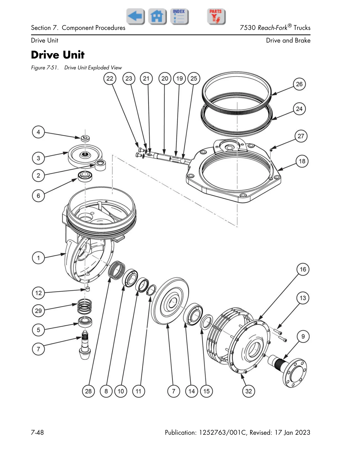
The Component Procedures section is organized by system and includes locator photos for the tractor, carriage, and underside components. It covers baselegs and load wheel replacement, steer tiller encoder service for both Fore/Aft and Dockstance stances, steer limit switch adjustment, steerable caster adjustment, steering linkage, primary and secondary control handle disassembly and repair for both stances, drive unit removal and disassembly with shim formulas, brake inspection and pad/coil replacement, deadman pedal adjustment, inertial dampener service, battery procedures, wiring and harness connector repair including Molex, Universal Mate-N-Lok, and AMPSEAL connectors, power cable repair, motor service for both DC and AC motors, steer amplifier removal and installation, cold storage conditioning, hydraulic system bleeding, hydraulic filters, lift pump replacement and priming, lift relief pressure adjustment, manual lowering of the fork carriage, auxiliary pump/motor service and priming, auxiliary relief pressure adjustment, lift/lower manifold, auxiliary manifold, standard reach manifold, Deep-Reach manifold, tilt/sideshift manifold, free lift cylinder, main lift cylinder, lift cylinder lowering cushion, reach cylinder, tilt cylinder, sideshift cylinder, main lift and free lift flow limiters, carriage bearings, mast shimming, carriage removal and installation, chain anchors, lift chains, height encoder belts, height reference switch, OTM hose and cable replacement, free lift feed hose, and complete mast disassembly and assembly including separation of tractor and mast, separation of telescopics, and back tilt and lateral lean inspection.

The Theory of Operation section explains traction system functional operation from battery connection through key-on, deadman pedal pressed, steering, and travel request for both primary and secondary control handles. It covers hydraulic system functional operation with component descriptions for the lift motor, lift motor encoder, lift motor temperature sensor, lift/lower pump, aux motor, aux motor encoder, aux motor temperature sensor, aux pump, hydraulic filters, main lift system, load holding valve, proportional lower valve, bypass lowering valves, flow limiter valve, check valves, relief valve, auxiliary system, reach/retract cylinder, sideshift cylinder, tilt cylinder, and auxiliary solenoids. It also covers brake operation and cold storage behavior. A complete pinout matrix lists connection, function description, theory of operation, normal level, signal source, and signal user for every terminal and connector pin on the lift truck.

Why This Manual Matters

Having the correct Raymond 7530 Reach-Fork Truck maintenance manual means you can diagnose faults accurately, perform scheduled maintenance at the right intervals, and carry out component repairs to the manufacturer’s specifications. The torque charts, lubrication specifications, service limits, and adjustment values in the appendix give you the exact figures needed for safe and correct reassembly. The fault code tables and diagnostic tests let you isolate problems without guesswork. Whether you are maintaining a fleet or servicing a single truck, this manual provides the complete technical information required to keep a 7530 Reach-Fork Truck operating correctly.

Get Instant Access

IMAGES PREVIEW

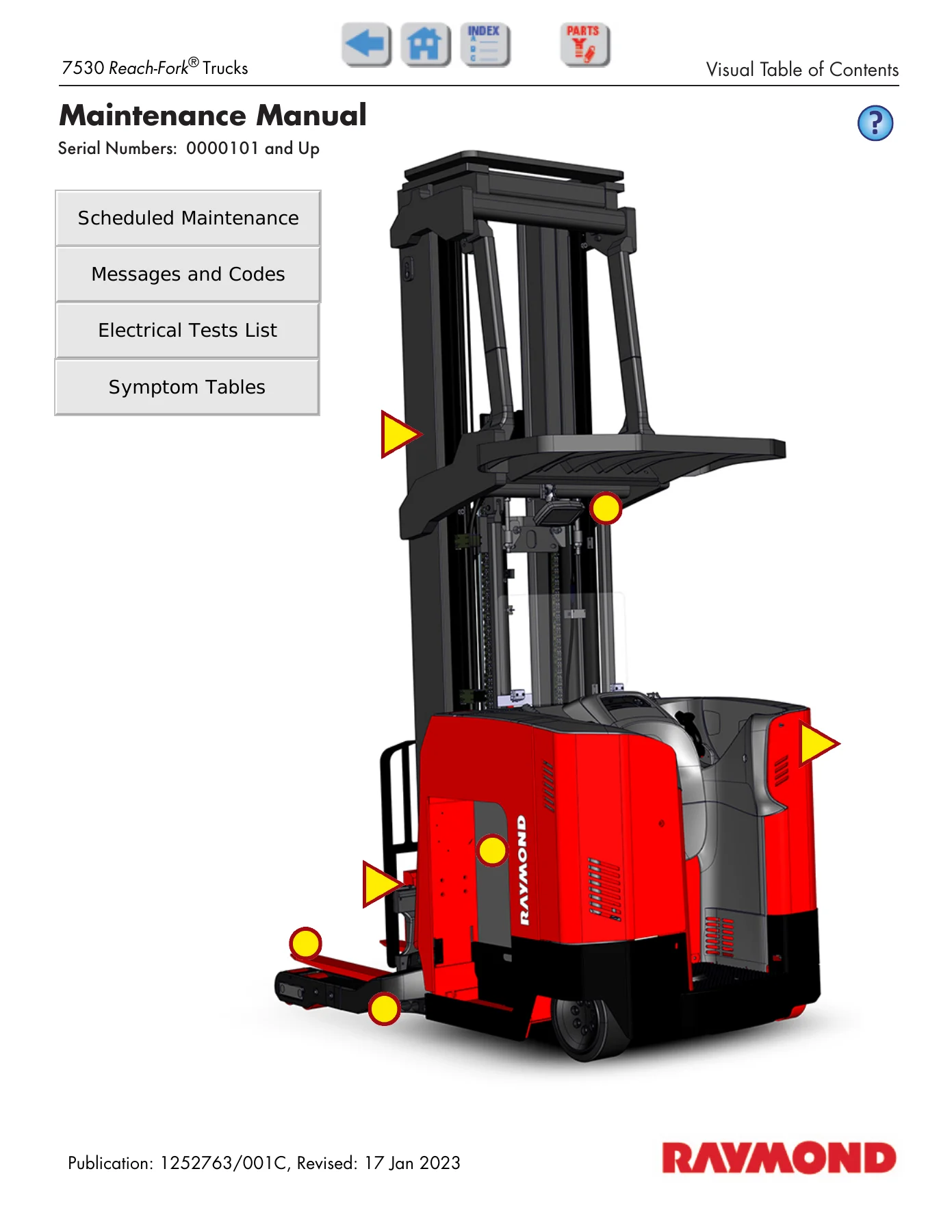
Raymond 7530 Reach-Fork Truck Maintenance Manual 1252763/001C - Serial 0000101 and Up — PDF page 1 preview
Raymond 7530 Reach-Fork Truck Maintenance Manual 1252763/001C - Serial 0000101 and Up — PDF page 2 preview
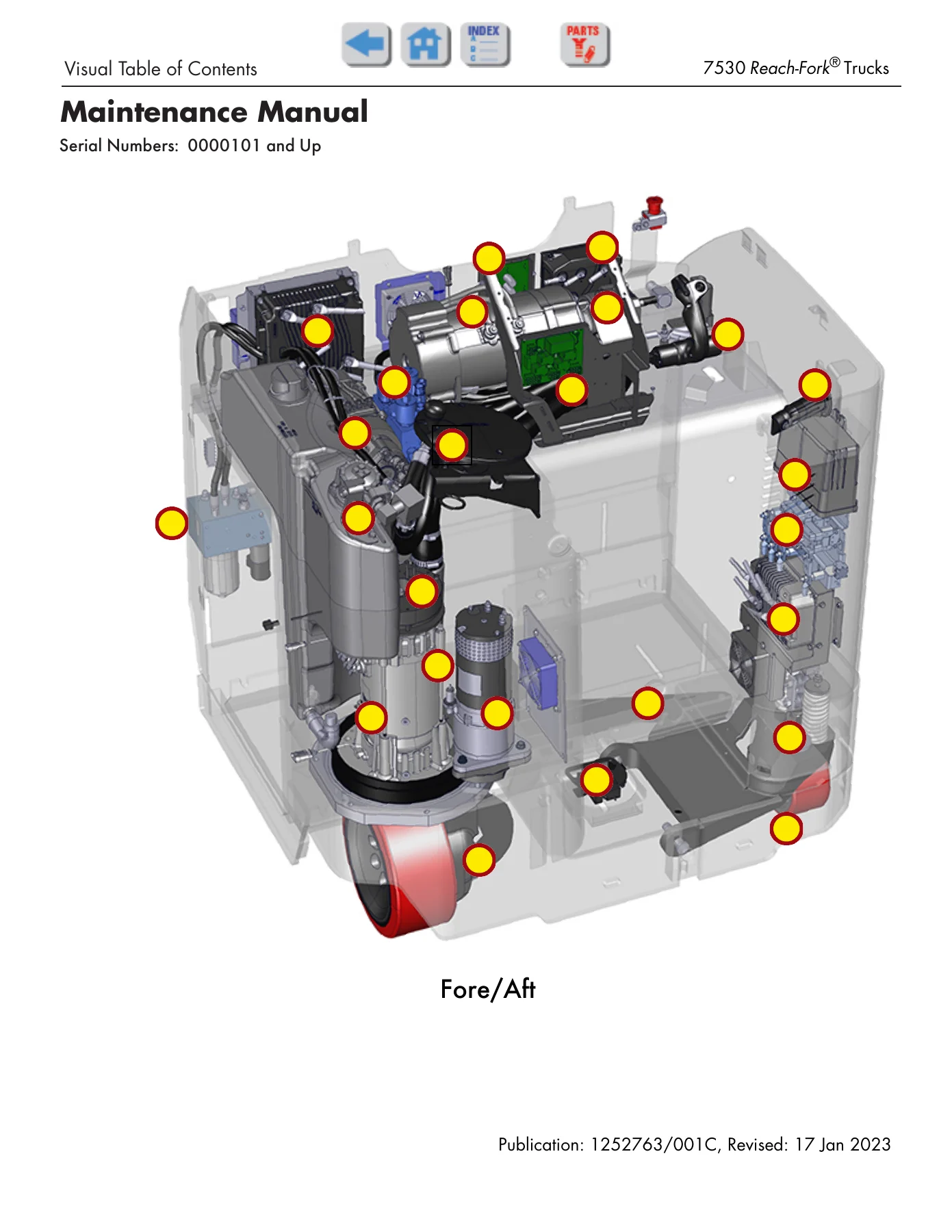
Raymond 7530 Reach-Fork Truck Maintenance Manual 1252763/001C - Serial 0000101 and Up — PDF page 287 preview

This Raymond 7530 maintenance manual is delivered as an instant PDF download after payment. There is no shipping and no waiting for a physical book. The file can be viewed on any device — computer, tablet, or smartphone — and individual pages can be printed when you need a paper copy in the workshop. With more than 480 pages of procedures, tests, specifications, and schematics, this is a complete service reference for the 7530 Reach-Fork Truck.
Reviews

There are no reviews yet.

Be the first to review “Raymond 7530 Reach-Fork Truck Maintenance Manual 1252763/001C – Serial 0000101 and Up”

What Our Customers Say

★★★★★ Live reviews from customers
Loading customer reviews...
0
    0
    Your Cart
    Your cart is emptyReturn to Shop
    🛒
    Recently Purchased
    🕒 verified order