★ TRUSTED BY 321,897+ PROFESSIONALS WORLDWIDE
🏢
Trusted Business
Verified & Licensed
🛡️
Virus Free Files
100% Safe Downloads
🔒
Secure Payment
SSL Protected
⚡
Instant Delivery
Available Immediately
Sale!

Raymond EASi Reach-Fork Truck EZ-C DZ-C Maintenance Manual 2005 – Publication 1019428A

Original price was: $39.95.Current price is: $23.95.

The complete Raymond maintenance manual for EASi Reach-Fork trucks, Series EZ-C and DZ-C. Publication 1019428A covers scheduled maintenance, fault codes, electrical tests, hydraulic procedures, component removal and installation, theory of operation, and full schematics. Instant PDF download.

⚡
Instant PDF Download
Available immediately
💾
Save to Your Device
Download & keep forever
🛡️
Antivirus Scanned
100% virus-free
🌍
Trusted Worldwide
175,000+ customers

Description

Raymond EASi Reach-Fork Truck EZ-C DZ-C Maintenance Manual

This is the complete maintenance manual for Raymond EASi Reach-Fork lift trucks, Series EZ-C and DZ-C, published by The Raymond Corporation under document number 1019428A, dated 15 March 2005. It is the reference technicians, fleet managers, and service departments use to keep these reach trucks running correctly — from routine scheduled maintenance through fault-code diagnostics, hydraulic repairs, electrical testing, and complete component overhauls.

The manual applies to the EASi Reach-Fork Truck, Series EZ-C and DZ-C, and to all subsequent releases of the product until otherwise indicated in new editions or bulletins. It supersedes earlier publications PDMM-0094, PDMM-0094-01, and the PDMM-0094-01.iNet release. The document also incorporates service bulletin and Product Improvement Notice content through 2004, including updates to firmware, power amplifier fans, reach thrust bearings, lift pump procedures, and carriage stops for specific mast configurations.

File Details

  • Manual Type: Maintenance Manual
  • Brand: Raymond (The Raymond Corporation)
  • Models Covered: EASi Reach-Fork Truck, Series EZ-C and DZ-C
  • Publication Number: 1019428A
  • Date Issued: 15 March 2005
  • Language: English
  • File Format: PDF
  • Page Count: Approximately 678 pages

Chapters Covered

  • Chapter 1 — How to Use This Manual: Map of the Manual, Design of the Manual, Abbreviations, Acronyms, and Symbols, START Page
  • Chapter 2 — Safety: Definitions, General Safety, Battery Safety, Static Precautions, Jacking Safety, Tie-Down for Transport, Welding Safety
  • Chapter 3 — Systems Overview: Introduction, Lift Truck Specifications, Operator Displays, Modes of Operation
  • Chapter 4 — Scheduled Maintenance: Maintenance Guidelines, Maintenance Minder Tool, Initial 90 Day/250 Deadman Hours, Every 180 Days or 500 Deadman Hours, Every 360 Days, Scheduled Maintenance Points, Motor Maintenance, Lubrication Points
  • Chapter 5 — Troubleshooting: How to Use This Chapter, Electrical Troubleshooting Guidelines, Electrostatic Discharge, Shorts to Frame Test, Hydraulic Troubleshooting Guidelines, Troubleshooting Procedure, Symptom Tables for Hydraulic Functions, Travel Functions, and Electrical Symptoms
  • Chapter 6 — Messages, Codes, and Tests: Firmware Changes, Modes of Operation, Messages and Codes Summary List and Tables, Power Amplifier LED Diagnostics, Electrical Codes, Electrical Connections, and the complete range of Analog Tests, Digital Input Tests, and Digital Output Tests
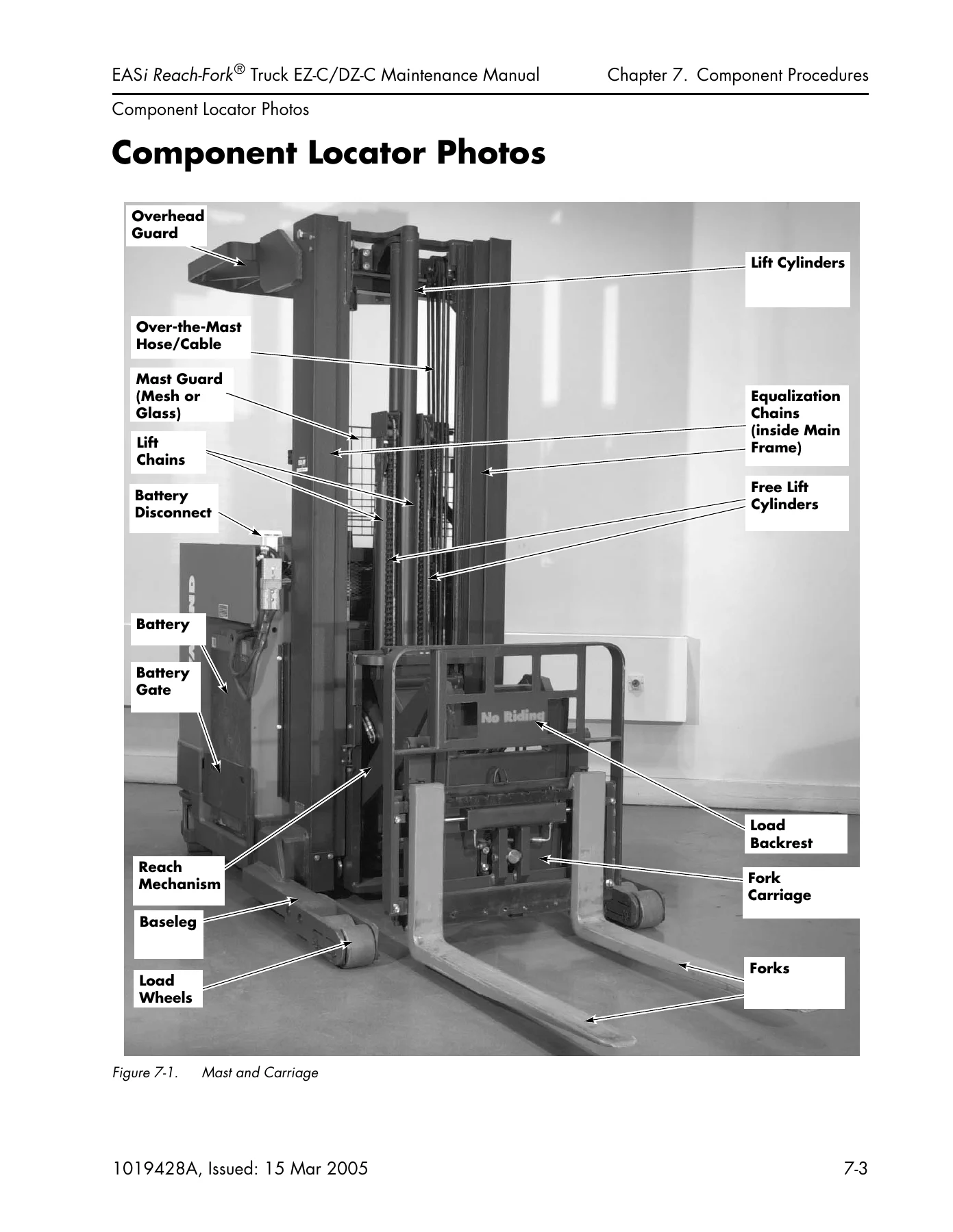
  • Chapter 7 — Component Procedures: Component Locator Photos, Covers and Finish, Steering and Controls, Drive and Brake, Electrical Components, Hydraulic Components, Mast/Chain/Hose/Cable, Options, and Firmware Configuration (FlashWare)
  • Chapter 8 — Theory of Operation: Traction System Functional Operation, Thermal Cut-Back, Brake System, Steering System, Lift/Aux System Functional Operation, and the complete Pinout Matrix
  • Chapter 9 — Appendix: Lubrication Specification Chart, Thread Adhesives/Sealants/Lubricants, Torque Charts, Decimal Equivalent Chart, Standard/Metric Conversions, Electrical Schematics, Power Distribution Diagrams, Hydraulic Schematics
  • Chapter 10 — Index: Complete alphabetical subject index

Complete PDF Bookmark Tree

Complete Bookmarks

The complete bookmarks in the “Raymond EASi Reach-Fork Truck EZ-C DZ-C Maintenance Manual 2005 – Publication 1019428A” are as follows:

EASi Reach-Fork® Lift Truckp. 1
Table of Contentsp. 3
Page Revision Pagep. 7
Service Bulletins Includedp. 9
Table 11. Service Bulletin content included in this manualp. 9
Product Improvement Notices Includedp. 10
Table 12. Product Improvement Notice content included in this manualp. 10
Chapter 1. How to Use This Manualp. 11
Map of the Manualp. 12
MAP.WMFp. 12
Design of the Manualp. 13
Abbreviations, Acronyms, and Symbolsp. 15
Table 11. Abbreviations, Acronyms, and Symbolsp. 15
How to Use This Manualp. 20
START Pagep. 20
Chapter 2. Safetyp. 23
Definitionsp. 24
Warning indicates a potentially hazardous situation, which, if not avoided, could result in death…p. 24
Caution indicates a potentially hazardous situation, which, if not avoided, could result in minor…p. 24
General Safetyp. 25
8B15004D.EPSp. 25
2823_001.epsp. 25
2823_002.epsp. 25
2823_003.epsp. 25
2823_004.epsp. 25
jewelry.epsp. 25
schedmnt.epsp. 26
8b15008d.epsp. 26
2823_005.epsp. 26
2823_006.epsp. 26
spills.epsp. 26
2823_007.epsp. 26
2823_008.epsp. 27
2823_009.epsp. 27
Battery Safetyp. 28
As a battery is being charged, an explosive gas mixture forms within and around each cell. If the…p. 28
Battery electrolyte is a solution of sulfuric acid and water. Battery acid causes burns. Should a…p. 28
25l6s014.epsp. 28
25L6S016.epsp. 28
04G6S059.epsp. 28
23L6S012.epsp. 28
04g6s058.epsp. 29
2823_004.epsp. 29
04g6s057.epsp. 29
27Y7S013.tifp. 29
09g6s047.tifp. 29
2823_010.epsp. 30
2823_011.epsp. 30
Static Precautionsp. 31
1. Place a static discharge wrist strap around your wrist. Connect the ground lead to the wrist s…p. 31
2. Connect the ground plug to the ESD ground jack on the lift truck. The ESD ground jack is locat…p. 31
4612_011.TIFp. 31
Figure 21. ESD Ground Jack Locationp. 31
3. Handle circuit boards by edges only. Avoid touching edge connectors.p. 31
4. If you will be removing or installing static-sensitive components, place them on a correctly g…p. 31
5. To transport static-sensitive components, including failed components being returned, place th…p. 31
mat2.tifp. 32
Figure 22. Anti-Static Kit with Wrist Strap and Matp. 32
Jacking Safetyp. 33
1. Lower the forks completely. Remove any load.p. 33
2. Place all controls in neutral.p. 33
3. Block the wheels to prevent movement of the vehicle.p. 33
4. Turn the key switch OFF and disconnect the battery connector.p. 33
5. If possible, stabilize the top of the mast with an overhead chain hoist.p. 33
6. Before jacking the lift truck, check the A-frame down-travel adjustment bolt. See Figure23. …p. 33
13Y7S001.TIFp. 33
Figure 23. Verify A-frame Down-Travel Adjustment Bolt (inertial dampener cover removed for clarity)p. 33
7. Place the jack under the designated jacking points. See Figure24.p. 33
Use extreme care whenever the lift truck is jacked up. Never block the lift truck between the tel…p. 33
toyrch_t.epsp. 33
Figure 24. Correct Jacking Locationsp. 33
To elevate the rear of the lift truck:p. 33
1. Place the jack in the designated jacking position. See Figure24.p. 33
2. Jack the rear of the lift truck so that the drive tire is off the floor no more than 3.25in. …p. 33
3. Block the lift truck in place.p. 33
To elevate either side of the lift truck:p. 33
1. Place the jack in the designated jacking position. See Figure24.p. 33
2. Jack the side of the truck so that the load wheel is off the floor no more than 0.5 in. (13mm).p. 34
3. Block the lift truck in place.p. 34
Tie-Down for Transportp. 35
1. Lower the forks and locate the lift truck in the center of the transport vehicle.p. 35
2. Using a suitable lifting device, remove the battery. See “Battery Safety” on page26.p. 35
3. Position the adjustable chain over and through the battery compartment.p. 35
4. Position an additional adjustable chain over and through the battery compartment.p. 35
5. Position the chain ends of one chain toward the front of the vehicle bed and the chain ends of…p. 35
6. Secure the battery according to the battery manufacturer’s instructions.p. 35
Welding Safetyp. 36
Flame cutting or welding on painted surfaces can produce potentially harmful fumes, smoke and vap…p. 36
Coating removal may be by mechanical methods, chemical methods or a combination of methods. Do fl…p. 36
04G6S059.epsp. 36
Disconnect the battery before you attempt to inspect, service or repair the lift truck.p. 36
2823_004.epsp. 36
Chapter 3. Systems Overviewp. 38
Introductionp. 39
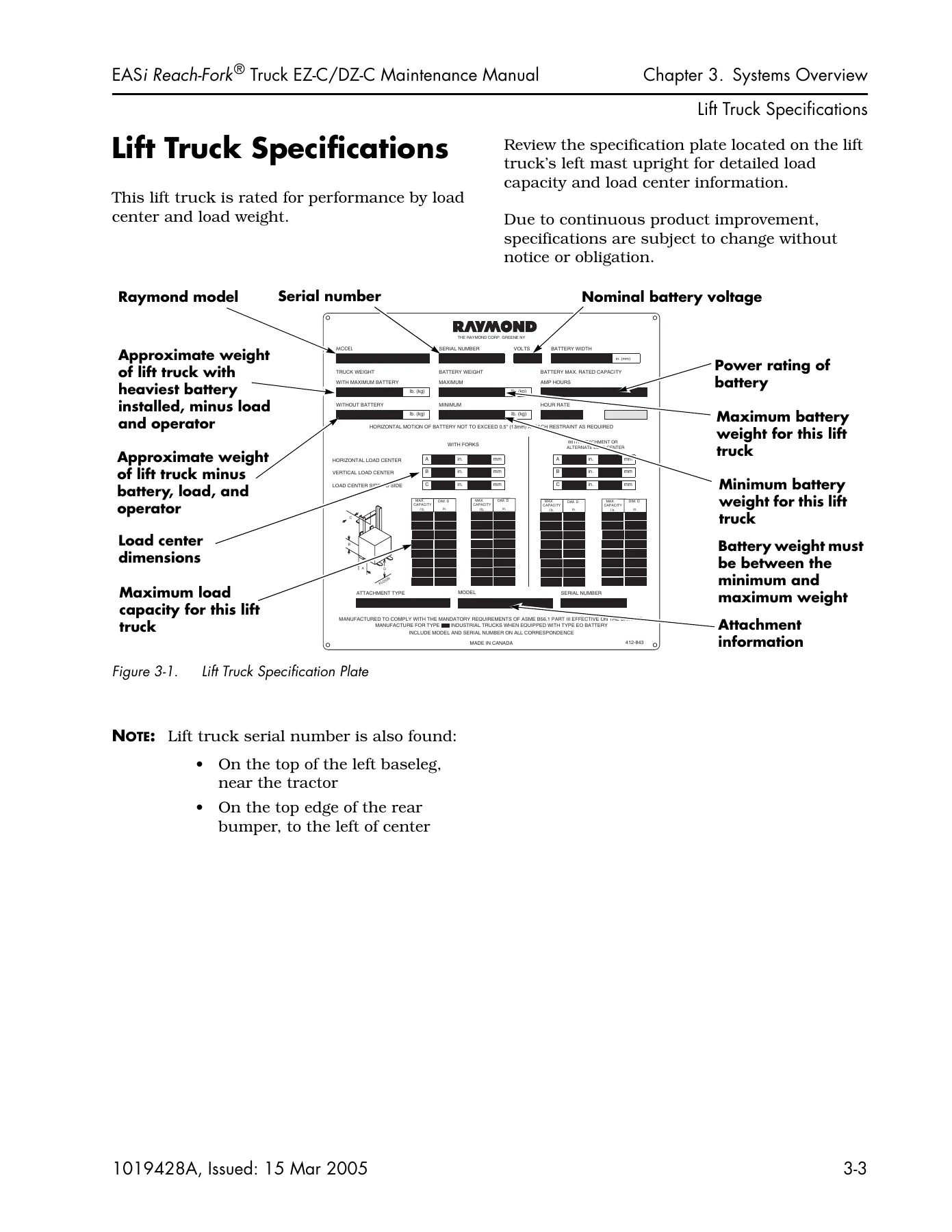
Lift Truck Specificationsp. 40
R412_843_B.EPSp. 40
Figure 31. Lift Truck Specification Platep. 40
Operator Displaysp. 42
13A7S029.EPSp. 42
Figure 32. Operator Display, Series EZp. 42
13A7S030.EPSp. 42
Figure 33. Operator Display, Series DZp. 42
1. Battery Chargep. 42
2. Lift Limit (optional)p. 42
3. Service Requiredp. 42
4. Drive Motor or Power Panel Over-Temperaturep. 42
5. Lift Truck Speedp. 42
6. Message Display (SelfTest, Hour Meters, BSOC, Load Weight], Clock/Calendar, Status and Error M…p. 42
7. Lift Bypass Button (location on Series EZ)p. 42
8. Key Switch (location on Series EZ)p. 42
Setting Default Displaysp. 42
Selecting “Off Deadman” defaultp. 42
1. While the deadman pedal is still up, move the directional/speed control full forward and hold …p. 42
2. Use the tilt up/down buttons to select the desired display. Release the tilt button and then r…p. 42
Selecting “On Deadman” defaultp. 43
1. While the deadman pedal is still up, move the directional/speed control to full forward and ho…p. 43
2. Step on the deadman pedal.p. 43
3. Use the tilt up/down buttons to select the desired display. Release the tilt button, step off …p. 43
Modes of Operationp. 44
Run Modep. 44
Program Modep. 44
Learn Modep. 44
Configure Modep. 44
Maintenance Modep. 44
Passwordsp. 44
Passwordp. 44
Superwordp. 44
Chapter 4. Scheduled Maintenancep. 47
Maintenance Guidelinesp. 48
Table 41. Service Type Definitionsp. 48
Maintenance Minder™ Toolp. 49
Factory Configurationp. 49
Enablingp. 49
Setting Time Interval and Action Optionp. 49
Changing Time Interval or Action Optionp. 49
Resetting Maintenance Minderp. 50
Disablingp. 50
Initial 90 Day/250 Deadman Hours (HD)p. 51
Every 180 Days or 500 Deadman Hours (HD)p. 52
Every 360 Daysp. 58
Scheduled Maintenance Pointsp. 59
4612_005.TIFp. 59
Figure 41. Scheduled Maintenance Points, Mast Viewp. 59
4155_005.TIFp. 60
Figure 42. Scheduled Maintenance Points, Tractor View (EZ-C shown)p. 60
3292_010.TIFp. 61
Figure 43. Scheduled Maintenance Points, Operator Compartment (DZ-C shown)p. 61
P5180009.TIFp. 62
Figure 44. Scheduled Maintenance Points, Undersidep. 62
Motor Maintenancep. 63
1. Wear safety glasses or goggles to protect your eyes from dust and debris.p. 63
2. Work in a well ventilated area.p. 63
3. Using an OSHA approved air nozzle, use clean, dry compressed air to blow carbon dust and other…p. 63
01A7S002.TIFp. 63
Figure 45. Motor cleaning with compressed airp. 63
Never use a chemical solvent to clean a motor, as it can carry carbon dust to inaccessible areas …p. 63
Cleaning a motor with solvents requires complete disassembly and drying, and should only be perfo…p. 63
Lubrication Pointsp. 64
Table 42.p. 64
P5180009.TIFp. 65
Figure 46. Lubrication Points, Steering Linkage and A-frame (underside view)p. 65
P5180010.TIFp. 65
P5180011.TIFp. 65
Figure 47. Lubrication Points, Steering Linkage and A-frame (top views)p. 65
P5180018.TIFp. 66
P5180019.TIFp. 66
Figure 48. Lubrication Points, Caster Wheel bearing and axlep. 66
4155_013.TIFp. 66
3422_005.TIFp. 66
Figure 49. Lubrication Points, Steering Shaft and Drive Unit; Fork Carriage Pivot Pinp. 66
lube-rch.pcxp. 67
Figure 410. Reach Assembly (Deep-Reach® shown)p. 67
P5180013.TIFp. 67
P5180017.TIFp. 67
Figure 411. Reach Mechanismp. 67
P5180016R.TIFp. 68
Figure 412. Lubrication Points, Reach Cylinderp. 68
4155_002.TIFp. 69
Figure 413. Lubrication Points, Mast and Carriagep. 69
13G6S092.TIFp. 69
13G6S104.TIFp. 69
Figure 414. Lubrication Points, Reach Mechanism; Sideshift Carriagep. 69
Chapter 5. Troubleshootingp. 72
How to Use This Chapterp. 73
Electrical Troubleshooting Guidelinesp. 74
Be sure to jack and block the lift truck whenever a troubleshooting procedure requires turning ke…p. 74
Unless otherwise directed, disconnect the battery connector when you check electrical circuits or…p. 74
Electrostatic Dischargep. 76
Shorts to Frame Testp. 77
1. Turn the key switch OFF and disconnect the battery connector.p. 77
2. To test the battery for shorts to case, connect a 12-volt test light to the battery case from …p. 77
3. With the battery disconnected from the lift truck, use a digital volt/ohm/ammeter on the Amper…p. 77
4. With the battery disconnected (or removed and disconnected) from the lift truck, use a digital…p. 77
a. To identify the cause of the short to frame, disconnect circuit components until the low resis…p. 78
b. The most likely areas to check are:p. 78
c. Repair or replace the component causing the low resistance condition, Then repeat Step 4.p. 78
d. Reconnect all other components previously disconnected, one at a time, measuring resistance be…p. 78
e. When, after all components are reconnected, you get readings greater than 1000 ohms, continue …p. 78
5. Reconnect the battery connector to the lift truck and turn the key switch ON. If the battery w…p. 78
6. Use a volt/ohm/ammeter on the current function to measure leakage current to the lift truck fr…p. 78
a. To identify the cause of the short to frame, disconnect circuit components until the leakage c…p. 78
b. The most likely areas to check are:p. 78
c. Repair or replace the component(s) causing the leakage current. Repeatstep6.p. 78
d. Reconnect all other components previously disconnected, measuring current between steps. If a …p. 78
7. When, after all components are reconnected, you get a reading less than 0.001A (1mA) there is …p. 78
STF_1.WMFp. 79
STF_2.WMFp. 80
Hydraulic Troubleshooting Guidelinesp. 81
4612_018.TIFp. 81
Figure 51. Blocking Carriagep. 81
After elevating or reaching the carriage for troubleshooting, be sure to use blocks to secure the…p. 81
Use extreme care when blocking the mast for any reason. Never remove a block when it is supportin…p. 81
Troubleshootingp. 82
Troubleshooting Procedurep. 82
TS1: START TROUBLESHOOTINGp. 83
TS1A.WMFp. 83
GEN1: General Troubleshootingp. 84
GEN_1.WMFp. 84
MISC: END1: End of Troubleshooting Procedurep. 85
END1.WMFp. 85
Troubleshootingp. 86
Symptom Tables: Hydraulic Functionsp. 86
Multiple Functions Affectedp. 86
No Auxiliary Functions Work (Reach/Retract, Tilt, Sideshift)p. 86
All Auxiliary Functions are Slowp. 87
Tiltp. 88
No Tilt; other Aux Functions OKp. 88
Slow Tilt; other Aux Functions OKp. 88
Sideshiftp. 89
No Sideshift or One Direction Only; Other Aux Functions OKp. 89
Sideshift – Slow Operation; Other Aux Functions OKp. 89
Reachp. 90
Reach – Does Not Work; Other Functions OKp. 90
Reach – Slow Operation; Other Aux Functions OKp. 90
Retractp. 91
Retract – Does Not Work; Other Functions OKp. 91
Retract – Slow Operation; Other Functions OKp. 91
Lift and Lowerp. 92
Intermittent Lift and Lowerp. 92
Lift Functionp. 93
No Liftp. 93
Slow Liftp. 94
Unable to Pick Up a Loadp. 95
Lower Functionp. 96
Slow Lowerp. 96
Intermittent Lowerp. 96
Load Drifting/Settlingp. 97
Symptom Tables: Travel Functionsp. 98
Slow or Sluggish Accelerationp. 98
Slow Travelp. 99
Symptom Tables: Electrical Symptomsp. 100
Electrical Motorsp. 100
Motor Overheatingp. 100
Operator Display Problemsp. 101
Scrambled or Intermittent Displayp. 101
Dead Lift Truckp. 102
Display is Dark; Lift Truck is NOT Operationalp. 102
Chapter 6. Messages, Codes, and Testsp. 105
Firmware Changesp. 106
Modes of Operationp. 107
Run Modep. 107
Program Modep. 107
Configure Modep. 107
Learn Modep. 107
Maintenance Modep. 107
Passwordsp. 107
Electronic Operator Keyp. 107
Passwordp. 107
Superwordp. 108
1. A single tone (chirp) occurs when:p. 108
2. A double tone (high/low) indicates the system has detected a fault condition.p. 108
3. A triple tone (high/medium/low) indicates one of the following:p. 108
4. A descending “arcade” tone indicates:p. 108
1. When the password prompt is displayed, an eight character field of underscores appears. Initia…p. 108
2. Use the sideshift left/right buttons to select a different character position. The selected po…p. 108
3. Once the character position is selected, use the tilt up/down buttons to select the desired nu…p. 108
4. Repeat steps 2 and 3 for the remaining characters in the Password or Superword.p. 109
5. When you have completed entering all the characters in the Password or Superword, press the ho…p. 109
6. If you enter an invalid Password or Superword, a descending “arcade” tone will sound and the f…p. 109
7. If you make a mistake while entering a character, repeat steps 2 through 5.p. 109
To change Password or Superwordp. 109
1. Enter the Configure Mode using the current Password or Superword. See “Using Configure Mode” o…p. 109
2. Use the tilt up/down buttons to scroll to the Password or Superword item.p. 109
3. With Password or Superword selected, press the horn button. (If Password was entered in step 1…p. 109
4. Enter the new password as described under “Entering a Password or Superword” above.p. 109
5. With the new password displayed, press the horn button.p. 109
6. Save the new password as described under “To Save New Values” on page66.p. 109
To Place the Lift Truck in Configure Modep. 109
1. Enter Program Mode as described on page64.p. 109
2. Enter Password or Superword.p. 109
3. If you entered the Password, the Operator display will show:p. 109
4. If you entered the Superword, the Operator Display will show:p. 109
To Configure an Itemp. 109
1. Use the tilt up/down buttons to move to the desired item.p. 109
2. To configure the selected item, press the horn button. Follow the directions on the Operator D…p. 109
To Configure Additional Itemsp. 110
If You Make a Mistakep. 110
To Save New Valuesp. 110
1. Use the tilt up/down buttons to scroll to the Quit Cfg item. Press the horn button.p. 110
2. The Operator Display will show:p. 110
3. Use the tilt up/down buttons to select Y (Yes). Press the horn button. Your new values are saved.p. 110
4. If you entered via Superword, the Operator Display will show:p. 110
5. The lift truck enters the Run Mode, beginning with SelfTest diagnostics.p. 110
If You Change Your Mind About Making Changesp. 110
1. Use the tilt up/down buttons to scroll to the Quit Cfg item. Press the horn button.p. 110
2. The Operator Display will show:p. 110
3. With N (No) selected, press the horn button. All changes are discarded.p. 110
4. If you entered via Superword, the Operator Display will show:p. 110
5. The lift truck enters Run Mode, beginning with SelfTest diagnostics.p. 110
To Reinstate Factory Default Settingsp. 110
1. Enter Configure Mode and use the tilt up button to select Default. Press the horn button. The …p. 110
2. Use the tilt up button to select the QuitCfg item. Press the horn button.p. 110
3. The Operator Display will show:p. 110
4. Use the tilt up/down buttons to select Y (Yes). Press the horn button. Factory default setting…p. 110
5. Use the tilt up/down buttons to select QuitPgm. Press the horn button.p. 110
6. If you entered via Superword, the Operator Display will show:p. 110
7. The lift truck enters Run Mode, beginning with SelfTest diagnostics.p. 110
Travel Settingsp. 111
Defaultp. 111
Speedp. 111
Accelp. 111
Liftp. 111
Coastp. 111
Cutoutp. 111
Unitsp. 111
Reachp. 111
Switch 1 (option)p. 111
Switch 2 (option)p. 111
AlarmT (option)p. 112
Elec Key (option)p. 112
Passwordp. 112
Superwrdp. 112
Versionp. 112
BSOCp. 112
Mnt Mindp. 112
Auto Offp. 113
Serial #p. 113
Clockp. 113
SMARTi®p. 113
ES Modep. 113
Disablep. 113
130 fpmp. 113
Minimump. 113
120 fpmp. 113
Maximump. 113
110 fpmp. 113
1. Enter Program Mode.p. 114
2. Enter Superword. The Operator Display shows:p. 114
3. Use the tilt up/down buttons to select Learn, then press the horn button. The Operator Display…p. 114
4. Use the tilt up/down buttons to select the desired category. The following categories can be s…p. 114
5. With the desired item selected, press the horn button.p. 114
Learn Controlsp. 114
1. Enter Learn Mode, select Controls, and press the horn button.p. 114
2. When you select Learn Controls, the Operator Display scrolls:p. 114
3. The Operator Display momentarily shows:p. 114
4. The Operator Display scrolls:p. 114
5. The Operator Display momentarily shows:p. 114
Learn Weightp. 114
1. From the Learn Menu, select Weight and press the horn button. The Operator Display scrolls:p. 114
2. When you press the horn button, the Operator Display momentarily shows:p. 114
3. The Operator Display scrolls:p. 114
4. When you press the horn button, the Operator Display momentarily shows:p. 114
5. The Operator Display scrolls:p. 114
By entering Static Maintenance Mode, you are disabling the safety circuits associated with the in…p. 115
While in Static Maintenance Mode: Elevate the drive tire off the floor. See “Jacking Safety” on p…p. 115
To Place the Lift Truck in Static Maintenance Modep. 115
1. Enter Program Mode.p. 115
2. Enter Superword.p. 115
3. Use the tilt up/down buttons to select Maint, then press the horn button.p. 115
4. The following selections are available from Maintenance Mode:p. 115
5. If you select Output tests, the Operator Display will scroll this warning:p. 115
6. Within a test category, tests numbers are displayed, in numerical sequence. Use the tilt up/do…p. 115
7. Analog and Input test results are displayed as soon as the test is selected, to the right of t…p. 115
8. Output tests must be started by the technician. Select the desired test number.p. 115
9. The Error Log stores the last twenty fault codes recorded on the lift truck. Entries are store…p. 115
a. To access the Error Log, use the tilt up/down buttons to select ErrorLog, then press the horn …p. 116
b. If no errors are stored, the message NoErrors appears in the display. After a few seconds, the…p. 116
c. If errors have been logged, the following menu options are active:p. 116
d. Pausing at an entry will result in a message scrolling the time, date, and BSOC value associat…p. 116
e. To clear and reset the error log, select the Clear option and press the horn button. The log i…p. 116
To Enable a Test For Active Maintenance Modep. 116
1. Enter Static Maintenance Mode.p. 116
2. Select the desired test and press the horn button. An asterisk (*) appears between the test nu…p. 116
3. Use the tilt up/down buttons to select additional tests from the same category. To select addi…p. 116
4. Quit Maintenance Mode and quit Program Mode. Allow the lift truck to enter Run Mode.p. 116
5. To choose the test that will be displayed when you are OFF the deadman pedal:p. 116
a. While the deadman pedal is still up, move the directional/speed control full forward and hold …p. 116
b. Use the tilt up/down buttons to scroll to the desired test. Release the tilt button and then r…p. 116
6. To choose the test that will be displayed when you are ON the deadman pedal:p. 116
a. While the deadman pedal is still up, move the directional/speed control to full forward and ho…p. 116
b. Step on the deadman pedal.p. 116
c. Use the tilt up/down buttons to scroll to the desired test. Release the tilt button, step off …p. 116
7. To scroll through the selected tests:p. 116
a. While the deadman pedal is still up, move the directional/speed control to the full forward po…p. 116
b. Use the tilt up/down buttons.p. 116
To Clear a Test From the Active Maintenance Listp. 116
1. Re-enter Maintenance Mode.p. 116
2. Use the tilt up/down buttons to select either Input or Analog and scroll to the test you want …p. 117
3. Press the horn button.p. 117
4. The asterisk will disappear. The test has now been disabled.p. 117
To Clear All Active Maintenance Tests At Oncep. 117
1. Go to the Program Mode via Superword.p. 117
2. Use the tilt up/down buttons to select Maint, then press the horn button. The Operator Display…p. 117
3. Use the tilt up/down buttons to select the ClrActM item. This item only appears if one or more…p. 117
4. Press the horn button. Active maintenance tests are disabled. The Operator Display shows:p. 117
Messages, Codes, and Testsp. 119
Messages and Codes Summary Listp. 119
Messages, Codes, and Testsp. 121
Messages and Codes Summary Tablesp. 121
Power Amplifier LED Diagnosticsp. 125
4155_030.TIFp. 125
Figure 61. Power Amplifier Status Indicator LEDp. 125
Fault Codesp. 126
Code 1Hp. 126
Check:p. 126
1. Make sure power cables are torqued correctly at both traction power amplifier and drive motor.p. 126
2. If BSOC cutout is set too low, a weak battery could result in overheating. Check specific grav…p. 126
3. Check motor for mechanical binding.p. 126
4. Check for dragging brake.p. 126
5. If problem still exists, evaluate the duty cycle and application.p. 126
Code 1Tp. 127
Code 1Vp. 128
Check:p. 128
1. Make sure power cables are torqued correctly at both lift power amplifier and lift motor.p. 128
2. If BSOC cutout is set too low, a weak battery could result in overheating. Check specific grav…p. 128
3. If problem still exists, evaluate the duty cycle and application.p. 128
Code 2Ap. 129
Check:p. 129
1. Make sure power cables are torqued correctly at both traction power amplifier and drive motor.p. 129
2. If BSOC cutout is set too low, a weak battery could result in overheating. Check specific grav…p. 129
3. Check motor for mechanical binding.p. 129
4. Check for dragging brake.p. 129
5. If problem still exists, evaluate the duty cycle and application.p. 129
Code 2Cp. 130
Check:p. 130
1. Make sure power cables are torqued correctly at both traction power amplifier and drive motor.p. 130
2. If BSOC cutout is set too low, a weak battery could result in overheating. Check specific grav…p. 130
3. Check motor for mechanical binding.p. 130
4. Check for dragging brake.p. 130
5. If problem still exists, evaluate the duty cycle and application.p. 130
Corrective Action:p. 130
Code 2Ep. 131
Check:p. 131
1. Make sure power cables are torqued correctly at both traction power amplifier and drive motor.p. 131
2. If BSOC cutout is set too low, a weak battery could result in overheating. Check specific grav…p. 131
3. Check motor for mechanical binding.p. 131
4. Check for dragging brake.p. 131
5. If problem still exists, evaluate the duty cycle and application.p. 131
Code 2Hp. 132
Code 2Mp. 133
Check:p. 133
1. Make sure power cables are torqued correctly at both traction power amplifier and drive motor.p. 133
Corrective Action:p. 133
Code 2Pp. 134
Corrective Action:p. 134
Code 2Rp. 135
Code 2Tp. 136
Check:p. 136
1. Make sure power cables are torqued correctly at both traction power amplifier and drive motor.p. 136
2. If BSOC cutout is set too low, a weak battery could result in overheating. Check specific grav…p. 136
3. Check motor for mechanical binding.p. 136
4. Check for dragging brake.p. 136
5. If problem still exists, evaluate the duty cycle and application.p. 136
Corrective Action:p. 136
Code 2Up. 137
Check:p. 137
1. Make sure power cables are torqued correctly at both traction power amplifier and drive motor.p. 137
2. If BSOC cutout is set too low, a weak battery could result in overheating. Check specific grav…p. 137
3. Check motor for mechanical binding.p. 137
4. Check for dragging brake.p. 137
5. If problem still exists, evaluate the duty cycle and application.p. 137
Code 2Vp. 138
Check:p. 138
1. Make sure power cables are torqued correctly at both traction power amplifier and drive motor.p. 138
2. If BSOC cutout is set too low, a weak battery could result in overheating. Check specific grav…p. 138
3. Check motor for mechanical binding.p. 138
4. Check for dragging brake.p. 138
5. If problem still exists, evaluate the duty cycle and application.p. 138
Corrective Action:p. 138
Code 42p. 139
Code 43p. 140
Code 44p. 141
Code 45p. 142
Code 4Bp. 143
Code 4Cp. 144
Code 4Dp. 145
Code 4Ep. 146
Code 59p. 147
Code 5Ap. 148
Code 5Bp. 149
Code 5Dp. 150
Code 5Gp. 151
Code 5Jp. 152
Code 5Lp. 153
Code 5Mp. 154
Code 5Np. 155
Code 5Pp. 156
Code 61p. 157
Code 62p. 158
Corrective Action:p. 158
Code 63p. 159
Code 6Ap. 160
Code 6Dp. 161
Code 6Fp. 162
Check:p. 162
1. Make sure power cables are torqued correctly at both traction power amplifier and drive motor.p. 162
2. If BSOC cutout is set too low, a weak battery could result in overheating. Check specific grav…p. 162
3. Check motor for mechanical binding.p. 162
4. If problem still exists, evaluate the duty cycle and application.p. 162
Code 6Gp. 163
Check:p. 163
1. Make sure power cables are torqued correctly at both traction power amplifier and drive motor.p. 163
2. If BSOC cutout is set too low, a weak battery could result in overheating. Check specific grav…p. 163
3. Check motor for mechanical binding.p. 163
4. If problem still exists, evaluate the duty cycle and application.p. 163
Code 6Kp. 164
Code 6Sp. 165
Check:p. 165
1. Make sure power cables are torqued correctly at both traction power amplifier and drive motor.p. 165
2. If BSOC cutout is set too low, a weak battery could result in overheating. Check specific grav…p. 165
3. Check lift motor and pump for mechanical binding.p. 165
4. If problem still exists, evaluate the duty cycle and application.p. 165
Code 6Tp. 166
Check:p. 166
1. Make sure power cables are torqued correctly at both traction power amplifier and drive motor.p. 166
Corrective Action:p. 166
Code 6Vp. 167
Check:p. 167
1. Make sure power cables are torqued correctly at both traction power amplifier and drive motor.p. 167
Corrective Action:p. 167
Code 6Wp. 168
Code 6Xp. 169
Check:p. 169
1. Make sure power cables are torqued correctly at both traction power amplifier and drive motor.p. 169
Corrective Action:p. 169
Code 6Yp. 170
Check:p. 170
1. Make sure power cables are torqued correctly at both traction power amplifier and drive motor.p. 170
2. If BSOC cutout is set too low, a weak battery could result in overheating. Check specific grav…p. 170
3. Check lift motor and pump for mechanical binding.p. 170
Corrective Action:p. 170
Code 80p. 171
Code 81p. 172
Code 83p. 173
Code 84p. 174
Corrective Action:p. 174
Code 87p. 175
Code 8Fp. 176
Code A0p. 177
Corrective Action:p. 177
1. Verify software versions by running Config Version.p. 177
2. Update lift truck software. See “Firmware Configuration” on page7259.p. 177
Code AGp. 178
Corrective Action:p. 178
1. If the problem is intermittent, check for shorts to frame. See “Shorts to Frame Test” on page…p. 178
2. The Operator Display could be bad.p. 178
3. The Vehicle Manager could be bad.p. 178
Code AHp. 179
Corrective Action:p. 179
1. If the problem is intermittent, check for shorts to frame. See “Shorts to Frame Test” on page…p. 179
2. Check the Firmware version by using the tilt up/down buttons to select “Firmware Version” on t…p. 179
3. If the correct firmware version appears on the Operator Display, replace the Operator Display.p. 179
Code AJp. 180
Corrective Action:p. 180
1. If the problem is intermittent, check for shorts to frame. See “Shorts to Frame Test” on page…p. 180
2. Check the Firmware version by using the tilt up/down buttons to select “Firmware Version” on t…p. 180
3. The Vehicle Manager could be malfunctioning. Replace the Vehicle Manager. Refer to “Vehicle Ma…p. 180
Code AKp. 181
Corrective Action:p. 181
1. If the problem is intermittent, check for shorts to frame. See “Shorts to Frame Test” on page…p. 181
2. Check the Firmware version by using the tilt up/down buttons to select “Firmware Version” on t…p. 181
3. The Vehicle Manager could be malfunctioning. Replace the Vehicle Manager. Refer to “Vehicle Ma…p. 181
Code ALp. 182
Corrective Action:p. 182
1. If the problem is intermittent, check for shorts to frame. See “Shorts to Frame Test” on page…p. 182
2. Check the Firmware version by using the tilt up/down buttons to select “Firmware Version” on t…p. 182
3. The Vehicle Manager could be malfunctioning. Replace the Vehicle Manager. Refer to “Vehicle Ma…p. 182
Code ECp. 183
Corrective Action:p. 183
1. If the problem is intermittent, check for shorts to frame. See “Shorts to Frame Test” on page…p. 183
2. Obtain new firmware, regardless of the version displayed on the Operator Display. Use the Flas…p. 183
3. The Vehicle Manager could be malfunctioning. Replace the Vehicle Manager. Refer to “Vehicle Ma…p. 183
Code F4p. 184
Corrective Action:p. 184
1. If the problem is intermittent, check for shorts to frame. See “Shorts to Frame Test” on page…p. 184
2. Obtain new firmware, regardless of the version displayed on the Operator Display. Use the Flas…p. 184
3. The Vehicle Manager could be malfunctioning. Replace the Vehicle Manager. Refer to “Vehicle Ma…p. 184
Code F5p. 185
Corrective Action:p. 185
1. If the problem is intermittent, check for shorts to frame. See “Shorts to Frame Test” on page…p. 185
2. Obtain new firmware, regardless of the version displayed on the Operator Display. Use the Flas…p. 185
3. The Vehicle Manager could be malfunctioning. Replace the Vehicle Manager. Refer to “Vehicle Ma…p. 185
Code F8p. 186
Corrective Action:p. 186
1. If the problem is intermittent, check for shorts to frame. See “Shorts to Frame Test” on page…p. 186
2. Obtain new firmware, regardless of the version displayed on the Operator Display. Use the Flas…p. 186
3. The Vehicle Manager could be malfunctioning. Replace the Vehicle Manager. Refer to “Vehicle Ma…p. 186
Code FGp. 187
Code FHp. 188
Check:p. 188
Code VCp. 189
Electrical Testsp. 191
Electrical Connectionsp. 191
Terminologyp. 191
8C04013S.TIFp. 191
Figure 62. Molex Jack and Pin Connectorp. 191
Circuit Card Connectorsp. 192
Vehicle Managerp. 192
4155_029.TIFp. 192
Figure 63. Vehicle Manager connectorsp. 192
Relay/Control Fuse Panelp. 193
R154_012_559.EPSp. 193
Figure 64. Relay/Control Fuse Panel connectorsp. 193
Messages, Codes, and Testsp. 195
Electrical Test Summary Listp. 195
Electrical Testsp. 197
Analog Testsp. 197
Test A04–Throttle Potentiometer Voltagep. 198
Run Testp. 198
1. The Operator Display will show the voltage that the Vehicle Manager reads from the throttle po…p. 198
2. The test is a success if the voltage displayed is within these limits:p. 198
Table 61.p. 198
Diagnosis and Repairp. 198
Use correct electrostatic discharge precautions. See “Static Precautions” on page29.p. 198
1. Verify +5V power supply. Run Test A26–Travel and Lift/Lower +5V DC Power Supply (Page6109).p. 198
2. If the 5V power supply is OK, the throttle potentiometer (VR1) or associated wiring could be b…p. 198
3. The Vehicle Manager could be malfunctioning. Replace the Vehicle Manager. Refer to “Vehicle Ma…p. 198
Test A05–Lift/Lower Potentiometer Voltagep. 199
Run Testp. 199
1. The Operator Display will show the voltage that the Vehicle Manager reads from the lift/lower …p. 199
2. The test is a success if the voltage displayed is within these limits:p. 199
Table 62.p. 199
Diagnosis and Repairp. 199
Use correct electrostatic discharge precautions. See “Static Precautions” on page29.p. 199
1. Verify +5V power supply. Run Test A26–Travel and Lift/Lower +5V DC Power Supply (Page6109).p. 199
2. If the 5V power supply is OK, the lift/lower potentiometer (VR2) or associated wiring could be…p. 199
3. The Vehicle Manager could be malfunctioning. Replace the Vehicle Manager. Refer to “Vehicle Ma…p. 199
Test A08–Traction Motor Temperaturep. 200
Limitsp. 200
Run Testp. 200
1. With the truck at rest and at ambient temperature, observe the operator display. It should sho…p. 200
2. If the temperature on the operator display seems different from the ambient temperature, the t…p. 200
Diagnosis and Repairp. 200
Use correct electrostatic discharge precautions. See “Static Precautions” on page29.p. 200
1. Turn the key switch OFF and disconnect the battery connector. Disconnect JPT3. Use an ohmmeter…p. 200
2. If the resistance is correct, disconnect JPT1 and check continuity of the cable JT1-PT3. Use a…p. 200
Table 63.p. 200
3. If cable JT1-PT3 has continuity, the traction power amplifier could be bad. Replace the tracti…p. 200
Test A09–Lift Motor Temperaturep. 201
Limitsp. 201
Run Testp. 201
1. With the truck at rest and at ambient temperature, observe the operator display. It should sho…p. 201
2. If the temperature on the operator display does not match the ambient temperature, then the te…p. 201
Diagnosis and Repairp. 201
Use correct electrostatic discharge precautions. See “Static Precautions” on page29.p. 201
1. Turn the key switch OFF and disconnect the battery connector. Disconnect JPL3. Use an ohmmeter…p. 201
2. If the resistance is correct, disconnect JPL1 and check continuity of the cable JL1-PL3.p. 201
Table 64.p. 201
3. If cable JL1-PL3 has continuity, the lift power amplifier could be bad. Replace the lift power…p. 201
Test A10–Traction Power Amplifier Heatsink Temperaturep. 202
Limitsp. 202
Run Testp. 202
Diagnosis and Repairp. 202
1. Check for dirt and debris in the traction power amplifier cooling fins.p. 202
2. Check operation of the power amplifier cooling fans. Run Test O23–Toggle Power Amplifier Fan…p. 202
3. The traction power amplifier could be malfunctioning. Replace the traction power amplifier. Se…p. 202
Test A11–Traction Motor Currentp. 203
Limitsp. 203
Run Testp. 203
Table 65.p. 203
Use correct electrostatic discharge precautions. See “Static Precautions” on page29.p. 203
Diagnosis and Repairp. 203
1. If any one phase differs significantly from the other two, check power cable continuity. Repla…p. 203
2. If power cable continuity is OK, check the following:p. 203
a. Make sure power cables are torqued correctly at both traction power amplifier and drive motor.p. 203
b. If BSOC cutout is set too low, a weak battery could result in overheating. Check specific grav…p. 203
c. Check motor for mechanical binding.p. 203
d. Check for dragging brake.p. 203
e. If problem still exists, evaluate the duty cycle and application.p. 203
3. Troubleshoot the drive motor. See “AC Motor Troubleshooting” on page7116.p. 203
a. Phases should read within 10% of each other. If not, the motor could run hot or sluggish.p. 203
b. If all phases give high readings, check drive motor and drive unit for binding.p. 203
Test A13–Pressure Sensor Voltagep. 204
Use extreme caution when working near the elevated forks.p. 204
Limitsp. 204
Table 66.p. 204
Run Testp. 204
Diagnosis and Repairp. 204
Use correct electrostatic discharge precautions. See “Static Precautions” on page29.p. 204
1. Check continuity between JPC11 and JPY4.p. 204
2. Connect a Digital Voltmeter (DVM) between JPY4-2(+) and JPY4-3(–). With no weight on the forks…p. 204
3. If the weight and voltage indicated are both low, the 12V supply to the sensor could be low. C…p. 204
Test A14–Power Supply +12V DCp. 205
Run Testp. 205
1. The Operator Display will show the voltage measured from the +12V power supply.p. 205
2. The test is a success if the voltage displayed is within these limits:p. 205
Table 67.p. 205
Diagnosis and Repairp. 205
Use correct electrostatic discharge precautions. See “Static Precautions” on page29.p. 205
1. Turn the key switch OFF and disconnect the battery connector.p. 205
2. Disconnect all connectors from the Vehicle Manager except JPC5 to the Operator Display and JPC…p. 205
3. Reconnect the battery connector and turn the key switch ON. Re-run the test.p. 205
a. If the Operator Display is dark, or the voltage is not within the reference range, go to step 4.p. 205
b. If the Operator Display is no longer dark, and the voltage is within the reference range, go t…p. 205
4. Turn the key switch OFF and disconnect the battery connector. Disconnect connector JPC5. Conne…p. 205
a. If the voltage is not within the reference range, the Vehicle Manager could be malfunctioning….p. 205
b. If the voltage is within the reference range, continue to step 5.p. 205
5. Turn the key switch OFF and disconnect the battery connector. Disconnect connector JPD1 from t…p. 205
a. Repair or replace wiring as necessary.p. 205
b. If the harness is OK, replace the Operator Display.p. 205
6. One of the disconnected circuits is drawing the 12V down. Isolate the failing circuit as follows:p. 205
a. Turn the key switch OFF and disconnect the battery connector. Reconnect one of the connectors …p. 205
b. Repeat step 6a until you identify the failing circuit.p. 205
Test A15–Battery Voltagep. 206
Run Testp. 206
1. The battery voltage as shown on the operator display should be 32 to 39 VDC.p. 206
2. If the numbers displayed are not in this range, the test is a failure.p. 206
Diagnosis and Repairp. 206
Use correct electrostatic discharge precautions. See “Static Precautions” on page29.p. 206
1. If the voltage is out of range, check the battery with a voltmeter. The battery could need ser…p. 206
2. Check the battery specific gravity. Consult the battery manufacturer’s guide for procedures an…p. 206
3. If you are running this test because lift does not function, enter Config mode and check the l…p. 206
4. Measure resistance from PF1-9 to PF2-1. You should read approximately 5.11Kohms due to the re…p. 206
a. If the resistance is incorrect, replace the relay control fuse panel or repair its associated …p. 206
b. If the resistance is OK, proceed to the next step.p. 206
5. Measure resistance from JPF2-1 to JPC8-7.p. 206
a. If continuity is not present, repair/replace the wiring harness.p. 206
b. If continuity is present, proceed to the next step.p. 206
6. The Vehicle Manager could be malfunctioning. Replace the Vehicle Manager. Refer to “Vehicle Ma…p. 206
Test A19–Lift Power Amplifier Heatsink Temperaturep. 207
Limitsp. 207
Run Testp. 207
Diagnosis and Repairp. 207
1. Check for dirt and debris in the lift power amplifier cooling fins.p. 207
2. Check operation of the power amplifier cooling fans. Run Test O23–Toggle Power Amplifier Fan…p. 207
3. The lift power amplifier could be malfunctioning. Replace the lift power amplifier. See “Lift …p. 207
Test A20–Lift Motor Currentp. 208
The lift carriage and forks could move during this test.p. 208
The area around the forks should be clear. The ceiling clearance should allow for the highest lift.p. 208
Limitsp. 208
Run Testp. 208
Use correct electrostatic discharge precautions. See “Static Precautions” on page29.p. 208
Diagnosis and Repairp. 208
1. If any one phase differs significantly from the other two, check power cable continuity. Repla…p. 208
2. If power cable continuity is OK, check the following:p. 208
a. Make sure power cables are torqued correctly at both traction power amplifier and drive motor.p. 208
b. If BSOC cutout is set too low, a weak battery could result in overheating. Also check specific…p. 208
c. Check lift motor and pump for mechanical binding.p. 208
d. If problem still exists, evaluate the duty cycle and application.p. 208
3. If all phases give high readings, there could be binding or a problem in the lift motor or mas…p. 208
Test A22–Traction Throttle Requestp. 209
Run Testp. 209
Table 68.p. 209
Diagnosis and Repairp. 209
Use correct electrostatic discharge precautions. See “Static Precautions” on page29.p. 209
Test A23–Lift Throttle Requestp. 210
Run Testp. 210
Table 69.p. 210
Diagnosis and Repairp. 210
Use correct electrostatic discharge precautions. See “Static Precautions” on page29.p. 210
Test A24–Traction Power Amplifier Internal Temperaturep. 211
Limitsp. 211
Run Testp. 211
Diagnosis and Repairp. 211
Use correct electrostatic discharge precautions. See “Static Precautions” on page29.p. 211
1. Run Test O23–Toggle Power Amplifier Fans (Page6159) to verify fan operation.p. 211
2. The traction power amplifier could be malfunctioning. Replace the traction power amplifier. Se…p. 211
Test A25–Lift Power Amplifier Internal Temperaturep. 212
Limitsp. 212
Run Testp. 212
Diagnosis and Repairp. 212
Use correct electrostatic discharge precautions. See “Static Precautions” on page29.p. 212
1. Run Test O23–Toggle Power Amplifier Fans (Page6159) to verify fan operation.p. 212
2. The lift amplifier could be malfunctioning. Replace the lift amplifier. See “Lift Power Amplif…p. 212
Test A26–Travel and Lift/Lower +5V DC Power Supplyp. 213
Run Testp. 213
Diagnosis and Repairp. 213
Use correct electrostatic discharge precautions. See “Static Precautions” on page29.p. 213
1. Turn the key switch OFF and disconnect the battery connector.p. 213
2. Disconnect JC6 from the Vehicle Manager.p. 213
3. Reconnect the battery connector and turn the key switch ON. The display should show 5V.p. 213
a. If 5V is present, replace the control handle. See “Control Handle” on page736.p. 213
b. If 5V is not present, replace the Vehicle Manager.p. 213
Test A27–Power Amplifier Fans Voltagep. 214
Electrical Testsp. 215
Digital Input Testsp. 215
Test I00–Deadman Switch (S2)p. 216
Do not conduct this test on a ramp.p. 216
Run Testp. 216
Table 610.p. 216
Diagnosis and Repairp. 216
Use correct electrostatic discharge precautions. See “Static Precautions” on page29.p. 216
1. The deadman switch S2 could be bad. Disconnect the wire from S2-NO. Use a digital ohmmeter to …p. 216
a. If there is continuity with the switch closed and no continuity with the switch open, go to st…p. 216
b. Replace the switch and reconnect the wire at S2-NO.p. 216
2. Carefully jumper pins JPC7-16 and JPC7-5. Remove the jumper when the test is complete.p. 216
a. If the display changes, the deadman switch or wiring is bad.p. 216
b. If the display does not change, go to step5.p. 216
3. Verify correct connection of the deadman switch harness to the Vehicle Manager at JPC7.p. 216
4. The cable from the Vehicle Manager to the deadman switch (S2-JC7) could be bad. Check the cabl…p. 216
5. If the display does not change, the Vehicle Manager could be malfunctioning. Replace the Vehic…p. 216
Test I01–Nested Switch (S19)p. 217
Use extreme caution when working around an elevated mast.p. 217
Lift only in an area with a ceiling height greater than the truck’s maximum elevated height.p. 217
Run Testp. 217
Table 611.p. 217
Diagnosis and Repairp. 217
Use correct electrostatic discharge precautions. See “Static Precautions” on page29.p. 217
1. Turn the key switch OFF and disconnect the battery connector. Disconnect the wire from S19-NO …p. 217
2. Use a digital ohmmeter to measure continuity between S19-NO and S19-COM.p. 217
a. If there is continuity with the switch closed and no continuity with the switch open, go to st…p. 217
b. Replace the switch and reconnect the wire at TS21-4.p. 217
3. Check for continuity between the following connection pairs:p. 217
Table 612.p. 217
a. If continuity is present in all pairs, go to step 4.p. 217
b. If continuity is not present in all pairs, repair or replace wiring segment as required.p. 217
4. Reconnect the wire removed in step 1 from TS21-4.p. 217
5. Carefully jumper from JPC9-3 to JPC10-10. Reconnect the battery connector and turn the key swi…p. 217
a. If the display changes, troubleshoot the switch and associated wiring. Remove jumper.p. 217
b. If the display does not change, the Vehicle Manager could be malfunctioning. Replace the Vehic…p. 217
Test I02–First Speed Limiting Switch (S10)p. 219
Do not attempt high speeds during this test. Speed limiting while elevated might be defeated duri…p. 219
Use extreme caution when working around an elevated mast.p. 219
Run Testp. 219
Table 613.p. 219
Diagnosis and Repairp. 219
Use correct electrostatic discharge precautions. See “Static Precautions” on page29.p. 219
1. Turn the key switch OFF and disconnect the battery connector. Disconnect connector JPS4.p. 219
2. Use a digital ohmmeter to measure continuity between S10-COM and S10-NO.p. 219
a. If there is continuity with the switch closed and no continuity with the switch open, go to st…p. 219
b. Replace the switch and reconnect connector JPS4.p. 219
3. Check for continuity between the following connection pairs:p. 219
Table 614.p. 219
a. If continuity is present in both pairs, go to step 4.p. 219
b. If continuity is not present in both pairs, replace the cable harness between PS4 and S10. Rec…p. 219
4. Check for continuity between the following connection pairs:p. 219
Table 615.p. 219
a. If continuity is present, go to step 5.p. 219
b. If continuity is not present in both pairs, replace the cable harness between JC7 and JS4. Rec…p. 220
5. Reconnect connector JPS4.p. 220
6. Jumper from JPC7-13 to JPC7-7 at the Vehicle Manager. Reconnect the battery connector and turn…p. 220
a. If the display changes, troubleshoot the switch and associated wiring. Remove the jumper.p. 220
b. If the display does not change, the Vehicle Manager could be malfunctioning. Replace the Vehic…p. 220
Test I03–Second Speed Limiting Switch (S11) (option)p. 221
Use extreme caution when working around an elevated mast.p. 221
Lift only in an area with a ceiling height greater than the truck’s maximum elevated height.p. 221
Run Testp. 221
Table 616.p. 221
Diagnosis and Repairp. 221
Use correct electrostatic discharge precautions. See “Static Precautions” on page29.p. 221
1. Turn the key switch OFF and disconnect the battery connector. Disconnect connector JPS5.p. 221
2. Use a digital ohmmeter to measure continuity between S11-COM and S11-NC.p. 221
a. If there is continuity with the switch closed and no continuity with the switch open, go to st…p. 221
b. Otherwise, switch S11 is bad. Replace the switch. Reconnect connector JPS5.p. 221
3. Check for continuity between the following connection pairs:p. 221
Table 617.p. 221
a. If continuity is present in both pairs, go to step 4.p. 221
b. If continuity is not present in both pairs, replace the cable harness between PS5 and S11. Rec…p. 221
4. Check for continuity between the following connection pairs:p. 221
Table 618.p. 221
a. If continuity is present in both pairs, go to step 5.p. 221
b. If continuity is not present in both pairs, replace the cable harness between JC12 and JS5. Re…p. 221
5. Reconnect connector JPS5.p. 222
6. Jumper from JPC12-6 to JPC12-3 at the Vehicle Manager. Reconnect the battery connector and tur…p. 222
a. If the display changes, troubleshoot the switch and associated wiring. Remove the jumper.p. 222
b. If the display does not change, the Vehicle Manager could be malfunctioning. Replace the Vehic…p. 222
Test I04–Lift Inhibit Bypass Switch (S12) (option)p. 223
Use extreme caution when working around an elevated mast.p. 223
Lift only in an area with a ceiling height greater than the truck’s maximum elevated height.p. 223
Run Testp. 223
Table 619.p. 223
Diagnosis and Repairp. 223
Use correct electrostatic discharge precautions. See “Static Precautions” on page29.p. 223
1. Turn the key switch OFF and disconnect the battery connector. Disconnect connector JPS9.p. 223
2. Use a digital ohmmeter to measure continuity between S12-1 and S12-2.p. 223
a. If there is continuity with the switch closed and no continuity with the switch open, go to st…p. 223
b. Otherwise, switch S12 is bad. Replace the switch. Reconnect connector JPS9.p. 223
3. Check for continuity between the following connection pairs:p. 223
Table 620.p. 223
a. If continuity is present in both pairs, go to step 4.p. 223
b. If continuity is not present in both pairs, replace the cable harness between PS9 and S12. Rec…p. 223
4. Check for continuity between the following connection pairs:p. 223
Table 621.p. 223
a. If continuity is present in both pairs, go to step 5.p. 223
b. If continuity is not present in both pairs, replace the cable harness between JC10 and JS9. Re…p. 223
5. Reconnect connector JPS9.p. 224
6. Jumper from JPC10-11 to JPC10-7 at the Vehicle Manager. Reconnect the battery connector and tu…p. 224
a. If the display changes, troubleshoot the switch and associated wiring. Remove the jumper.p. 224
b. If the display does not change, the Vehicle Manager could be malfunctioning. Replace the Vehic…p. 224
Test I05–Lift Limit Switch (S13) (option)p. 225
Use extreme caution when working around an elevated mast.p. 225
Lift only in an area with a ceiling height greater than the truck’s maximum elevated height.p. 225
Run Testp. 225
Table 622.p. 225
Diagnosis and Repairp. 225
Use correct electrostatic discharge precautions. See “Static Precautions” on page29.p. 225
1. Turn the key switch OFF and disconnect the battery connector. Disconnect connector JPS6.p. 225
2. Use a digital ohmmeter to measure continuity between S13-1 and S13-2.p. 225
a. If there is continuity with the switch closed and no continuity with the switch open, go to st…p. 225
b. Otherwise, switch S13 is bad. Replace the switch. Reconnect connector JPS6.p. 225
3. Check for continuity between the following connection pairs:p. 225
Table 623.p. 225
a. If continuity is present in both pairs, go to step 4.p. 225
b. If continuity is not present in both pairs, replace the cable harness between PS6 and S13. Rec…p. 225
4. Check for continuity between the following connection pairs:p. 225
Table 624.p. 225
a. If continuity is present in both pairs, go to step 5.p. 225
b. If continuity is not present in both pairs, replace the cable harness between JC12 and JS6. Re…p. 225
5. Reconnect connector JPS6.p. 226
6. Jumper from JPC12-5 to JPC12-2. Reconnect the battery connector and turn the key switch ON. Ru…p. 226
a. If the display changes, troubleshoot the switch and associated wiring. Remove the jumper.p. 226
b. If the display does not change, the Vehicle Manager could be malfunctioning. Replace the Vehic…p. 226
Test I06–Reach Switch (S4)p. 227
Run Testp. 227
Table 625.p. 227
Diagnosis and Repairp. 227
Use correct electrostatic discharge precautions. See “Static Precautions” on page29.p. 227
1. The harness from the switch might not be plugged correctly into the Vehicle Manager at JPC6. I…p. 227
2. Switch S4 could be bad. Turn the key switch OFF and disconnect the battery connector. Jumper J…p. 227
a. If the display changes as indicated, switch S4 or control handle harness wiring is bad. Remove…p. 227
b. If the display does not change as indicated with the jumper installed, the Vehicle Manager cou…p. 227
Test I07–Retract Switch (S5)p. 228
Run Testp. 228
Table 626.p. 228
Diagnosis and Repairp. 228
Use correct electrostatic discharge precautions. See “Static Precautions” on page29.p. 228
1. The harness from the switch might not be plugged correctly into the Vehicle Manager at JPC6. I…p. 228
2. Switch S5 could be bad. Turn the key switch OFF and disconnect the battery connector. Jumper J…p. 228
a. If the display changes as indicated, switch S5 or the control handle harness wiring is bad. Re…p. 228
b. If the display does not change as indicated with the jumper installed, the Vehicle Manager cou…p. 228
Test I08–Tilt Up Switch (S6)p. 229
Run Testp. 229
Table 627.p. 229
Diagnosis and Repairp. 229
Use correct electrostatic discharge precautions. See “Static Precautions” on page29.p. 229
1. The harness from the switch might not be plugged correctly into the Vehicle Manager at JPC6. I…p. 229
2. Switch S6 could be bad. Turn the key switch OFF and disconnect the battery connector. Jumper J…p. 229
a. If the display changes as indicated, switch S6 or the control handle harness wiring is bad. Re…p. 229
b. If the display does not change as indicated with the jumper installed, the Vehicle Manager cou…p. 229
Test I09–Tilt Down Switch (S7)p. 230
Run Testp. 230
Table 628.p. 230
Diagnosis and Repairp. 230
Use correct electrostatic discharge precautions. See “Static Precautions” on page29.p. 230
1. The harness from the switch might not be plugged correctly into the Vehicle Manager at JPC6. I…p. 230
2. Switch S7 could be bad. Turn the key switch OFF and disconnect the battery connector. Jumper J…p. 230
a. If the display changes as indicated, switch S7 or the control handle harness wiring is bad. Re…p. 230
b. If the display does not change as indicated with the jumper installed, the Vehicle Manager cou…p. 230
Test I10–Sideshift Right Switch (S9)p. 231
Run Testp. 231
Table 629.p. 231
Diagnosis and Repairp. 231
Use correct electrostatic discharge precautions. See “Static Precautions” on page29.p. 231
1. The harness from the switch might not be plugged correctly into the Vehicle Manager at JPC6. I…p. 231
2. Switch S9 could be bad. Turn the key switch OFF and disconnect the battery connector. Jumper J…p. 231
a. If the display changes as indicated, switch S9 or the control handle harness wiring is bad. Re…p. 231
b. If the display does not change as indicated with the jumper installed, the Vehicle Manager cou…p. 231
Test I11–Sideshift Left Switch (S8)p. 232
Run Testp. 232
Table 630.p. 232
Diagnosis and Repairp. 232
Use correct electrostatic discharge precautions. See “Static Precautions” on page29.p. 232
1. The harness from the switch might not be plugged correctly into the Vehicle Manager at JPC6. I…p. 232
2. Switch S8 could be bad. Turn the key switch OFF and disconnect the battery connector. Jumper J…p. 232
a. If the display changes as indicated, switch S8 or the control handle harness wiring is bad. Re…p. 232
b. If the display does not change as indicated with the jumper installed, the Vehicle Manager cou…p. 232
Test I14–Steering Fuse (FU1)p. 233
When this test is activated and the deadman pedal is depressed, the steer motor/pump will activate.p. 233
Run Testp. 233
Table 631.p. 233
Diagnosis and Repairp. 233
Use correct electrostatic discharge precautions. See “Static Precautions” on page29.p. 233
1. Fuse FU1 could be bad. Turn the key switch OFF and disconnect the battery connector. Remove an…p. 233
2. The connections at FU1 could be corroded or loose. Clean and retighten as necessary.p. 233
3. The FU1 sense circuit wiring could be disconnected or broken. Use a digital ohmmeter to check …p. 233
Table 632.p. 233
4. The steering contactor or coil might not be working correctly. Run Test O01.p. 233
5. The Vehicle Manager could be malfunctioning. Replace the Vehicle Manager. Refer to “Vehicle Ma…p. 233
Test I15–Horn Switch (S3)p. 234
Run Testp. 234
Table 633.p. 234
Diagnosis and Repairp. 234
Use correct electrostatic discharge precautions. See “Static Precautions” on page29.p. 234
1. If the display changes when the horn button is depressed, but the horn does not sound, the hor…p. 234
2. The harness from the switch might not be plugged correctly into the Vehicle Manager at JPC6. I…p. 234
3. Switch S3 could be bad. Turn the key switch OFF and disconnect the battery connector. Jumper J…p. 234
a. If the display changes as indicated, switch S3 or the control handle harness wiring is bad. Re…p. 234
b. If the display does not change as indicated with the jumper installed, the Vehicle Manager cou…p. 234
Test I19–Drive Motor Speed Sensorp. 235
Conduct this test in an area free of obstructions, with ample room for maneuvering.p. 235
Run Testp. 235
Table 634.p. 235
Diagnosis and Repairp. 235
Use correct electrostatic discharge precautions. See “Static Precautions” on page29.p. 235
1. Turn the key switch OFF and disconnect the battery connector. Use a DVM and connect (+) lead t…p. 235
2. Connect (+) lead to JPT1-5 and (–) lead to TP4. With no travel, the DVM should read either les…p. 235
a. If the DVM readings are not as stated, go to step 4.p. 235
b. If the DVM readings are as stated, replace the traction power amplifier. See “Traction Power A…p. 235
3. Connect (+) lead to JPT1-6. Leave (–) lead on TP4. With no travel, the DVM should read either …p. 235
a. If the DVM readings are not as stated, go to step 4.p. 235
b. If the DVM readings are as stated, replace the traction power amplifier. See “Traction Power A…p. 235
4. Turn the key switch OFF and disconnect the battery connector. Disconnect connectors JPT1 and J…p. 235
5. Use a digital ohmmeter to measure continuity between the following connection pairs:p. 236
Table 635.p. 236
a. If continuity is present in all pairs, go to step 6.p. 236
b. If continuity is not present in all pairs, repair/replace the cable harness between PT2 and JS…p. 236
6. Check for continuity between the following connection pairs:p. 236
Table 636.p. 236
a. If continuity is present in all pairs, go to step 7.p. 236
b. If continuity is not present in all pairs, repair/replace the cable harness between JT1 and PS…p. 236
7. Replace drive motor speed sensor. See “Speed Sensor” on page7129.p. 236
Test I20–Lift Motor Speed Sensorp. 237
Conduct this test in an area free of obstructions, with ample room for maneuvering.p. 237
Run Testp. 237
Table 637.p. 237
Diagnosis and Repairp. 237
Use correct electrostatic discharge precautions. See “Static Precautions” on page29.p. 237
1. Turn the key switch OFF and disconnect the battery connector. Use a DVM and connect (+) lead t…p. 237
2. Connect (+) lead to JPL1-5 and (–) lead to TP4. With no lift, the DVM should read either less …p. 237
a. If the DVM readings are not as stated, go to step 4.p. 237
b. If the DVM readings are as stated, replace the lift power amplifier. See “Lift Power Amplifier…p. 237
3. Connect (+) lead to JPL1-6. Leave (–) lead on TP4. With no lift, the DVM should read either le…p. 237
a. If the DVM readings are not as stated, go to step 4.p. 237
b. If the DVM readings are as stated, replace the lift power amplifier. See “Lift Power Amplifier…p. 237
4. Turn the key switch OFF and disconnect the battery connector. Disconnect connectors JPL1 and J…p. 237
5. Use a digital ohmmeter to measure continuity between the following connection pairs:p. 238
Table 638.p. 238
a. If continuity is present in all pairs, go to step 6.p. 238
b. If continuity is not present in all pairs, repair/replace the cable harness between PL2 and JL…p. 238
6. Reconnect connector JPL2.p. 238
7. Replace lift motor speed sensor. See “Speed Sensor” on page7129.p. 238
Test I21–Staging Switch (S14)p. 239
Use extreme caution when working around an elevated mast.p. 239
Lift only in an area with a ceiling height greater than the truck’s maximum elevated height.p. 239
Run Testp. 239
Table 639.p. 239
Diagnosis and Repairp. 239
Use correct electrostatic discharge precautions. See “Static Precautions” on page29.p. 239
1. Turn the key switch OFF and disconnect the battery connector. Disconnect the wire from S14-NC …p. 239
2. Use a digital ohmmeter to measure continuity between S14-NC and S14-COM.p. 239
a. If there is continuity with the switch open and no continuity with the switch closed, go to st…p. 239
b. Otherwise, switch S14 is bad. Replace the switch. Reconnect the wire at TS21-6.p. 239
3. Check for continuity between the following connection pairs:p. 239
Table 640.p. 239
a. If continuity is present, go to step 4.p. 239
b. If continuity is not present in both pairs, repair or replace wiring as required. Reconnect th…p. 239
4. Check for continuity between the following connection points:p. 239
Table 641.p. 239
a. If continuity is present in both pairs, go to step 5.p. 239
b. If continuity is not present in both pairs, repair or replace wiring as necessary. Reconnect t…p. 239
5. Check for continuity between the following connection points:p. 239
Table 642.p. 239
a. If continuity is present in both pairs, go to step 6.p. 240
b. If continuity is not present in both pairs, repair or replace wiring as necessary. Reconnect t…p. 240
6. With the wire disconnected, reconnect the battery connector and turn the key switch ON. Run Te…p. 240
7. Jumper from JPC9-3 to JPC10-8 at the Vehicle Manager. Reconnect the battery connector and turn…p. 240
a. If the display changes, troubleshoot the switch and associated wiring.p. 240
b. If the display does not change, the Vehicle Manager could be malfunctioning. Replace the Vehic…p. 240
Test I22–Lift Cut Off Switch (S20) (option)p. 241
Use extreme caution when working around an elevated mast.p. 241
Lift only in an area with a ceiling height greater than the truck’s maximum elevated height.p. 241
Run Testp. 241
Table 643.p. 241
Diagnosis and Repairp. 241
Use correct electrostatic discharge precautions. See “Static Precautions” on page29.p. 241
1. Turn the key switch OFF and disconnect the battery connector. Disconnect connector JPS8.p. 241
2. Use a digital ohmmeter to measure continuity between S20-1 and S20-2.p. 241
a. If there is continuity with the switch closed and no continuity with the switch open, go to st…p. 241
b. Otherwise, switch S20 is bad. Replace the switch. Reconnect connector JPS8.p. 241
3. Check for continuity between the following connection pairs:p. 241
Table 644.p. 241
a. If continuity is present in both pairs, go to step 4.p. 241
b. If continuity is not present in both pairs, replace the cable harness between PS8 and S20. Rec…p. 241
4. Check for continuity between the following connection pairs:p. 241
Table 645.p. 241
a. If continuity is present in both pairs, go to step 5.p. 241
b. If continuity is not present in both pairs, replace the cable harness between JC10 and JS8. Re…p. 241
5. Reconnect connector JPS8.p. 241
6. With the wire disconnected, reconnect the battery connector and turn the key switch ON. Run Te…p. 241
7. Jumper from JPC10-12 to JPC10-6 at the Vehicle Manager. Reconnect the battery connector and tu…p. 241
a. If the display changes, troubleshoot the switch and associated wiring.p. 242
b. If the display does not change, the Vehicle Manager could be malfunctioning. Replace the Vehic…p. 242
Test I23–CAN Bus Testp. 243
Run Testp. 243
Diagnosis and Repairp. 243
Use correct electrostatic discharge precautions. See “Static Precautions” on page29.p. 243
One Letter Missingp. 243
1. Make sure power is applied to the associated device by verifying that the power LED is illumin…p. 243
2. Verify continuity of BUS+/BUS-;p. 243
a. Disconnect all CAN Bus connections.p. 243
b. Use a digital ohmmeter to measure resistance at any connector. If resistance is not 120 ohms, …p. 243
c. Connect each power amplifier. Use a digital ohmmeter to measure resistance at any connector. I…p. 243
d. Connect the Vehicle Manager. Use a digital ohmmeter to measure resistance at any connector.p. 243
e. If the truck is equipped with SMARTi, connect it. Use a digital ohmmeter to measure resistance…p. 243
f. Repair/replace components/wiring as necessary.p. 243
3. Replace the associated power amplifier.p. 243
All Letters missingp. 243
1. Verify power is applied to both power amplifiers and SMARTi (if so equipped).p. 243
2. SMARTi is an option. If SMARTi is not installed on the lift truck, an (S) will not appear on t…p. 243
3. If (T, L, S) are all missing, put Test I23 in Active Maintenance mode. Turn the key switch OFF…p. 243
4. Disconnect the traction power amplifier at connector JPT1. Reconnect the battery connector and…p. 243
a. If the (L) returns, replace the traction power amplifier and rerun test. See “Traction Power A…p. 243
b. If the (L) does not return: Turn the key switch OFF and disconnect the battery connector.p. 244
5. Reconnect the traction power amplifier at connector JPT1. Disconnect the lift power amplifier …p. 244
a. If the (T) returns, replace the lift power amplifier and rerun test. See “Lift Power Amplifier…p. 244
b. If the (T) does not return, turn the key switch OFF and disconnect the battery.p. 244
6. If SMARTi is not installed, go to step 7 and disregard references to SMARTi. Reconnect the lif…p. 244
a. If the (T) or (L) returns, replace the SMARTi module and rerun the test.p. 244
b. If the (T,L,S) are all still missing: Turn the key switch OFF and disconnect the battery conne…p. 244
7. Use a digital ohmmeter to measure resistance between Bus+ and Bus– at the cable side of the Ve…p. 244
Table 646.p. 244
a. If the reference values are not correct, troubleshoot that line.p. 244
b. If the reference values are correct, the Vehicle Manager could be malfunctioning. Replace the …p. 244
Electrical Testsp. 245
Digital Output Testsp. 245
Test O00–Toggle the TPC Contactorp. 246
Jack the drive wheels off the floor for this test.p. 246
The traction system might not act as expected during this test. If the traction power amplifier i…p. 246
Run Testp. 246
1. Turn the key switch OFF and disconnect the battery connector.p. 246
2. Disconnect the wire from TPC-X.p. 246
3. Connect an ammeter in series with TPC as follows:p. 246
a. Positive (+) to TPC-X terminalp. 246
b. Negative (–) to wire removed from TPC-Xp. 246
4. Use the tilt up/down buttons to toggle the test ON and OFF. The operator display will show ON …p. 246
5. You should see:p. 246
Table 647.p. 246
Diagnosis and Repairp. 246
Use correct electrostatic discharge precautions. See “Static Precautions” on page29.p. 246
1. Verify the precharge circuit is functioning correctly. Connect a DVM between AC traction amp (…p. 246
a. If this is correct, proceed to step 2.p. 246
b. If this is not correct, go to step 5.p. 246
2. Turn the key switch OFF and disconnect the battery connector.p. 246
3. Check for binding in the contactor. Repair or replace as necessary. Proceed to step 9.p. 246
4. If the truck exhibited the following symptoms, check the integrity of drive motor power cables…p. 246
5. Disconnect wires from the relay control fuse panel at T3 and JPF2.p. 246
6. Use a digital ohmmeter to measure resistance from T3 to PF2-7 on the relay/fuse card. Correct …p. 246
a. If the resistance at ambient temperature is OK, there has been an overcurrent condition in the…p. 247
b. If the resistance at ambient temperature is not OK, a thermistor on the relay control fuse pan…p. 247
7. Measure resistance from PS11-2 to TPC-2. You should read approximately 15 ohms.p. 247
a. If the resistance is not OK, repair/replace resistor TR and/or its associated wiring.p. 247
b. If the resistance is OK, proceed to the next step.p. 247
8. Measure resistance from T3 to JS11-2.p. 247
a. If continuity is not present, repair/replace the wiring harness.p. 247
b. If continuity is present, proceed to the next step.p. 247
9. Measure resistance from TPC-2 to TPC-X.p. 247
a. If continuity is not present, repair/replace the wiring harness.p. 247
b. If continuity is present, proceed to the next step.p. 247
10. Use a digital ohmmeter and check the resistance of the TPC coil. With the wires removed from …p. 247
11. Use a digital ohmmeter to measure continuity between each of the connection pairs in the tabl…p. 247
Table 648.p. 247
12. Check for shorts to B- or frame. Repair/replace wires as needed.p. 247
13. If no shorts exist, replace the Traction Power Amplifier.p. 247
Test O01–Toggle the STR Contactorp. 248
Do not attempt to drive the truck while conducting this test.p. 248
The steer system might not act as expected during this test. The steer motor will run when the co…p. 248
Run Testp. 248
1. Turn the key switch OFF and disconnect the battery connector.p. 248
2. Disconnect the wire from STR-X.p. 248
3. Connect an ammeter in series with STR as follows:p. 248
a. Positive (+) to STR-X terminalp. 248
b. Negative (–) to wire removed from STR-Xp. 248
4. Use the tilt up/down buttons to toggle the test ON and OFF. The operator display will show ON …p. 248
5. You should see:p. 248
Table 649.p. 248
Diagnosis and Repairp. 248
Use correct electrostatic discharge precautions. See “Static Precautions” on page29.p. 248
1. Turn the key switch OFF and disconnect the battery connector.p. 248
2. Check for binding in the contactor. Repair or replace as necessary.p. 248
3. Use a digital ohmmeter and check the resistance of the coil. With the wires removed from the X…p. 248
4. Use a digital ohmmeter to measure continuity between each of the connection pairs in the table…p. 248
Table 650.p. 248
5. Check for continuity between JPF2-7 on the contactor fuse panel and JPC8-13 (B+KC) at the Vehi…p. 248
6. Reconnect the battery connector and turn the key switch ON. Measure the voltage between JPF2-7…p. 248
7. Toggle Test O01 ON. Use a DVM to measure voltage between STR-X (+) and TP4(–). You might init…p. 249
8. With Test O01 toggled ON, use a DVM to measure voltage between JPC8-14 (+) and TP4 (–).p. 249
a. If B+KC (36V) is present at JPC8-14 but not STR-Y, repair/replace the harness.p. 249
b. If B+KC (36V) is not present, the Vehicle Manager could be malfunctioning. Replace the Vehicle…p. 249
Test O02–Toggle the LPC Contactorp. 250
Ceiling height should be higher than the maximum elevated height of the lift truck under test.p. 250
The lift system might not act as expected during this test. If the lift power amplifier is shorte…p. 250
Run Testp. 250
1. Turn the key switch OFF and disconnect the battery connector.p. 250
2. Disconnect the wire from LPC-X.p. 250
3. Connect an ammeter in series with LPC as follows:p. 250
a. Positive (+) to LPC-X terminalp. 250
b. Negative (–) to wire removed from LPC-Xp. 250
4. Use the tilt up/down buttons to toggle the test ON and OFF. The operator display will show ON …p. 250
5. You should see:p. 250
Table 651.p. 250
Diagnosis and Repairp. 250
Use correct electrostatic discharge precautions. See “Static Precautions” on page29.p. 250
1. Verify the precharge circuit is functioning correctly. Connect a DVM between AC lift amp (+) a…p. 250
a. If this is correct, proceed to step 2.p. 250
b. If this is not correct, go to step 4.p. 250
2. Turn the key switch OFF and disconnect the battery connector.p. 250
3. Check for binding in the contactor. Repair or replace as necessary. Proceed to step 8.p. 250
4. Disconnect wires from the relay control fuse panel at T4 and JPF2.p. 250
5. Use a digital ohmmeter to measure resistance from T4 to PF2-7 on the relay/fuse card. Resistan…p. 250
a. If the resistance at ambient temperature is OK, there has been an overcurrent condition in the…p. 251
b. If the resistance at ambient temperature is not OK, a thermistor on the relay control fuse pan…p. 251
6. Measure resistance from PS11-4 to LPC-2. You should read approximately 15 ohms.p. 251
a. If the resistance is not OK, repair/replace resistor LR and/or its associated wiring.p. 251
b. If the resistance is OK, proceed to the next step.p. 251
7. Measure resistance from T4 to JS11-4.p. 251
a. If continuity is not present, repair/replace the wiring harness.p. 251
b. If continuity is present, proceed to the next stepp. 251
8. Measure resistance from LPC-2 to LPC-X.p. 251
a. If continuity is not present, repair/replace the wiring harness.p. 251
b. If continuity is present, proceed to the next stepp. 251
9. Use a digital ohmmeter and check the resistance of the LPC coil. With the wires removed from t…p. 251
10. Use a digital ohmmeter to measure continuity between each of the connection pairs in the tabl…p. 251
Table 652.p. 251
11. Check for shorts to B- or frame.p. 251
Test O04–Toggle the DIRA (SOL5B) Solenoidp. 252
Run Testp. 252
1. Turn the key switch OFF and disconnect the battery connector.p. 252
2. Disconnect wire SOL5B-1 from the DIRA solenoid.p. 252
3. Connect a digital ammeter in series with the DIRA solenoid coil, positive lead (+) to the wire…p. 252
4. Reconnect the battery connector and turn the key switch ON.p. 252
5. Run Test O04 and toggle the solenoid coil ON. Use the tilt up/down buttons to toggle the test …p. 252
6. The ammeter should read 650 to 900 milliamps.p. 252
a. If the ammeter reading is correct, the solenoid coil is functioning correctly electrically.p. 252
b. If the solenoid is not working correctly, check for a mechanical problem in the valve, such as…p. 252
Diagnosis and Repairp. 252
Use correct electrostatic discharge precautions. See “Static Precautions” on page29.p. 252
1. Disconnect JPC9 from the Vehicle Manager. Measure the resistance between JC9-7 and JC9-4. The …p. 252
2. Connect the (+) lead of a DVM to JP9-4 and the (–) lead to JP9-7 on the Vehicle Manager.p. 252
a. Toggle the test ON. The DVM should read 24V.p. 252
b. Toggle the test OFF. The DVM should read 0V.p. 252
Test O05–Toggle the DIRB (SOL5T) Solenoidp. 253
Run Testp. 253
1. Turn the key switch OFF and disconnect the battery connector.p. 253
2. Disconnect wire SOL5T-1 from the DIRB solenoid.p. 253
3. Connect a digital ammeter in series with the DIRB solenoid coil, positive lead (+) to the wire…p. 253
4. Reconnect the battery connector and turn the key switch ON.p. 253
5. Run Test O05 and toggle the solenoid coil ON. Use the tilt up/down buttons to toggle the test …p. 253
a. If the ammeter reading is correct, the solenoid coil is functioning correctly electrically.p. 253
b. If the solenoid is not working correctly, check for a mechanical problem in the valve, such as…p. 253
Diagnosis and Repairp. 253
Use correct electrostatic discharge precautions. See “Static Precautions” on page29.p. 253
1. Disconnect JPC9 from the Vehicle Manager. Measure the resistance between JC9-10 and JC9-4. The…p. 253
2. Connect the (+) lead of a DVM to PC9-4 and the (–) lead to JPC9-10 on the Vehicle Manager.p. 253
a. Toggle the test ON. The DVM should read 24V.p. 253
b. Toggle the test OFF. The DVM should read 0V.p. 253
Test O06–Toggle the Reach Solenoidp. 254
Run Testp. 254
1. Turn the key switch OFF and disconnect the battery connector.p. 254
2. Disconnect wire REACH-1 from the reach solenoid.p. 254
3. Connect a digital ammeter in series with the reach solenoid coil, positive lead (+) to the wir…p. 254
4. Reconnect the battery connector and turn the key switch ON.p. 254
5. Run Test O06 and toggle the solenoid coil ON. Use the tilt up/down buttons to toggle the test …p. 254
a. If the ammeter reading is correct, the solenoid coil is functioning correctly electrically.p. 254
b. If the solenoid is not working correctly, check for a mechanical problem in the valve, such as…p. 254
Diagnosis and Repairp. 254
Use correct electrostatic discharge precautions. See “Static Precautions” on page29.p. 254
1. Disconnect JPC9 from the Vehicle Manager. Measure the resistance between JC9-3 (+) and JC9-8 (…p. 254
2. Connect the (+) lead of a DVM to PC9-3 and the (–) lead to PC9-8 on the Vehicle Manager.p. 254
a. Toggle the test ON. The DVM should read 24V.p. 254
b. Toggle the test OFF. The DVM should read 0V.p. 254
Test O07–Toggle the Tilt Solenoidp. 255
Run Testp. 255
1. Turn the key switch OFF and disconnect the battery connector.p. 255
2. Disconnect wire TILT-1 from the tilt solenoid.p. 255
3. Connect a digital ammeter in series with the tilt solenoid coil, positive lead (+) to the wire…p. 255
4. Reconnect the battery connector and turn the key switch ON.p. 255
5. Run Test O07 and toggle the solenoid coil ON. Use the tilt up/down buttons to toggle the test …p. 255
a. If the ammeter reading is correct, the solenoid coil is functioning correctly electrically.p. 255
b. If the solenoid is not working correctly, check for a mechanical problem in the valve, such as…p. 255
Diagnosis and Repairp. 255
Use correct electrostatic discharge precautions. See “Static Precautions” on page29.p. 255
1. Disconnect JPC9 from the Vehicle Manager. Measure the resistance between JC9-3 (+) and JC9-1 (…p. 255
2. Connect the (+) lead of a DVM to PC9-3 and the (–) lead to PC9-1 on the Vehicle Manager.p. 255
a. Toggle the test ON. The DVM should read 24V.p. 255
b. Toggle the test OFF. The DVM should read 0V.p. 255
Test O08–Toggle the Sideshift Solenoidp. 256
Run Testp. 256
1. Turn the key switch OFF and disconnect the battery connector.p. 256
2. Disconnect wire SIDESHIFT-1 from the sideshift solenoid.p. 256
3. Connect a digital ammeter in series with the sideshift solenoid coil, positive lead (+) to the…p. 256
4. Reconnect the battery connector and turn the key switch ON.p. 256
5. Run Test O08 and toggle the solenoid coil ON. Use the tilt up/down buttons to toggle the test …p. 256
a. If the ammeter reading is correct, the solenoid coil is functioning correctly electrically.p. 256
b. If the solenoid is not working correctly, check for a mechanical problem in the valve, such as…p. 256
Diagnosis and Repairp. 256
Use correct electrostatic discharge precautions. See “Static Precautions” on page29.p. 256
1. Disconnect JPC9 from the Vehicle Manager. Measure the resistance between JC9-3 (+) and JC9-12 …p. 256
2. Connect the (+) lead of a DVM to PC9-3 and the (–) lead to PC9-12 on the Vehicle Manager.p. 256
a. Toggle the test ON. The DVM should read 24V.p. 256
b. Toggle the test OFF. The DVM should read 0V.p. 256
Test O09–Toggle the EQ (SOL6) Solenoidp. 257
Run Testp. 257
1. Turn the key switch OFF and disconnect the battery connector.p. 257
2. Disconnect wire SOL6-1 from the equalizing (EQ) solenoid.p. 257
3. Connect a digital ammeter in series with the equalizing (EQ) solenoid coil, positive lead (+) …p. 257
4. Reconnect the battery connector and turn the key switch ON.p. 257
5. Run Test O09 and toggle the solenoid coil ON. Use the tilt up/down buttons to toggle the test …p. 257
a. If the ammeter reading is correct, the solenoid coil is functioning correctly electrically.p. 257
b. If the solenoid is not working correctly, check for a mechanical problem in the valve, such as…p. 257
Diagnosis and Repairp. 257
Use correct electrostatic discharge precautions. See “Static Precautions” on page29.p. 257
1. Disconnect JPC9 from the Vehicle Manager. Measure the resistance between JC9-9 and JC9-4. The …p. 257
2. Connect the (+) lead of a DVM to PC9-4 and the (–) lead to PC9-9 on the Vehicle Manager.p. 257
a. Toggle the test ON. The DVM should read 24V.p. 257
b. Toggle the test OFF. The DVM should read 0V.p. 257
Test O11–Toggle the Load Hold (SOL1) Solenoidp. 258
Run Testp. 258
1. Turn the key switch OFF and disconnect the battery connector.p. 258
2. Disconnect wire SOL1-1 from the load hold solenoid.p. 258
3. Connect a digital ammeter in series with the load hold solenoid coil, positive lead (+) to the…p. 258
4. Reconnect the battery connector and turn the key switch ON.p. 258
5. Run Test O11 and toggle the solenoid coil ON. Use the tilt up/down buttons to toggle the test …p. 258
a. If the ammeter reading is correct, the solenoid coil is functioning correctly electrically.p. 258
b. If the solenoid is not working correctly, check for a mechanical problem in the valve, such as…p. 258
Diagnosis and Repairp. 258
Use correct electrostatic discharge precautions. See “Static Precautions” on page29.p. 258
1. Disconnect JPC9 from the Vehicle Manager. Measure the resistance between JC9-6 and JC9-4. The …p. 258
2. Connect the (+) lead of a DVM to PC9-4 and the (–) lead to PC9-6 on the Vehicle Manager.p. 258
a. Toggle the test ON. The DVM should read 24V.p. 258
b. Toggle the test OFF. The DVM should read 0V.p. 258
Test O12–Ramp the Proportional Lower (SOL2) Solenoidp. 259
The lowering function normally uses the proportional lower solenoid in conjunction with the load …p. 259
Run Testp. 259
1. 0 to 90% will appear on the operator display. Use the tilt up/down buttons to increase or decr…p. 259
2. Use the following table as a reference guide for testing. All values are approximate.p. 259
Table 653.p. 259
Diagnosis and Repairp. 259
Use correct electrostatic discharge precautions. See “Jacking Safety” on page211.p. 259
If the truck will not lower:p. 259
1. Turn the key switch OFF and disconnect the battery connector.p. 259
2. Disconnect the wires to the coil of proportional lower solenoid SOL2.p. 259
3. Use a digital ohmmeter to measure the resistance of the coil. The resistance should be 13.5 to…p. 259
4. Reconnect the SOL2 coil wires.p. 259
5. Voltage method:p. 259
a. Connect a digital voltmeter between SOL2-2 (+) and SOL2-1 (–) on the solenoid.p. 259
b. Reconnect the battery connector and turn the key switch ON.p. 259
c. Run Test 012. While ramping the display, the voltmeter should indicate the values listed in th…p. 259
d. While ramping the display, use the digital voltmeter to measure voltage between JPC9-5 (–) and…p. 259
Test O18–Toggle the Hornp. 260
Run Testp. 260
1. Use the tilt up/down buttons to toggle the test ON and OFF. The operator display will show ON …p. 260
2. When the ENTER key is pressed the horn should sound. If it does not sound, then this test is a…p. 260
Diagnosis and Repairp. 260
Use correct electrostatic discharge precautions. See “Static Precautions” on page29.p. 260
1. Turn the key switch OFF and disconnect the battery connector.p. 260
2. Disconnect the wires from the horn terminals. Use a digital voltmeter to measure the voltage t…p. 260
a. If voltage is not present, go to step 3 below.p. 260
b. If voltage is present, replace the horn.p. 260
3. Use a digital ohmmeter to measure continuity between each of the pin sets in the table below:p. 260
Table 654.p. 260
4. If wiring continuity is OK, verify voltage between JPC8-15 (+) and JPC8-16 (–). If voltage is …p. 260
Test O19–Audible Alarmp. 261
Run Testp. 261
Diagnosis and Repairp. 261
Use correct electrostatic discharge precautions. See “Static Precautions” on page29.p. 261
1. If you are able to access the maintenance mode, then the keypad and associated wiring is worki…p. 261
2. If the sonalert does not work, the operator display cable JC5-JD1 could be bad. Turn the key s…p. 261
3. Connect the (+) lead of a DVM to JPC5-1 and the (–) lead to JPC5-5 on the Vehicle Manager. Hol…p. 261
a. If voltage is present, replace the operator display.p. 261
b. If the voltage is not present, the Vehicle Manager could be malfunctioning. Replace the Vehicl…p. 261
Test O20–Travel Alarm (Option)p. 262
Run Testp. 262
Diagnosis and Repairp. 262
Use correct electrostatic discharge precautions. See “Static Precautions” on page29.p. 262
1. Turn the key switch OFF and disconnect the battery connector.p. 262
2. Remove fuse FU4. Use a digital ohmmeter and check FU4 for continuity.p. 262
a. If there is continuity, go to step 3.p. 262
b. If there is no continuity, replace the fuse.p. 262
3. Connect a meter to H2 (+) and H2 (–). Run the test. If the meter indicates near battery voltag…p. 262
4. If the meter does not indicate near battery voltage, connect the (+) lead of the meter to JPC1…p. 262
5. If the correct voltage is not present, the Vehicle Manager could be malfunctioning. Replace th…p. 262
Test O23–Toggle Power Amplifier Fansp. 263
Run Testp. 263
Diagnosis and Repairp. 263
Use correct electrostatic discharge precautions. See “Static Precautions” on page29.p. 263
1. Use a DVM and connect (+) lead to the appropriate fan connection, JPB1-1 or JPB2-1; and (–) le…p. 263
2. If voltage is not present, connect (+) lead to JPC9-11 and (–) lead to JPC10-9 at the Vehicle …p. 263
3. If voltage is not present, the Vehicle Manager could be malfunctioning. Replace the Vehicle Ma…p. 263
Test O24–Toggle the Lift Blocking (SOL7) Solenoidp. 264
Run Testp. 264
1. Turn the key switch OFF and disconnect the battery connector.p. 264
2. Disconnect wire SOL7-1 from the lift blocking solenoid.p. 264
3. Connect a digital ammeter in series with the lift blocking solenoid coil, positive lead (+) to…p. 264
4. Reconnect the battery connector and turn the key switch ON.p. 264
5. Run Test O24 and toggle the solenoid coil ON. Use the tilt up/down buttons to toggle the test …p. 264
a. If the ammeter reading is correct, the solenoid coil is functioning correctly electrically.p. 264
b. If the solenoid is not working correctly, check for a mechanical problem in the valve, such as…p. 264
Diagnosis and Repairp. 264
Use correct electrostatic discharge precautions. See “Static Precautions” on page29.p. 264
1. Disconnect JPC8 from the Vehicle Manager. Measure the resistance between JC8-19 and JC8-14. Th…p. 264
2. Connect the (+) lead of a DVM to PC8-14 and the (–) lead to PC8-19 on the Vehicle Manager.p. 264
a. Toggle the test ON. The DVM should read 24V.p. 264
b. Toggle the test OFF. The DVM should read 0V.p. 264
Test O25–Toggle the Aux Select (SOL4) Solenoidp. 265
Run Testp. 265
1. Turn the key switch OFF and disconnect the battery connector.p. 265
2. Disconnect wire SOL4-1 from the aux select solenoid.p. 265
3. Connect a digital ammeter in series with the aux select solenoid coil, positive lead (+) to th…p. 265
4. Reconnect the battery connector and turn the key switch ON.p. 265
5. Run Test O25 and toggle the solenoid coil ON. Use the tilt up/down buttons to toggle the test …p. 265
a. If the ammeter reading is correct, the solenoid coil is functioning correctly electrically.p. 265
b. If the solenoid is not working correctly, check for a mechanical problem in the valve, such as…p. 265
Diagnosis and Repairp. 265
Use correct electrostatic discharge precautions. See “Static Precautions” on page29.p. 265
1. Disconnect JPC9 from the Vehicle Manager. Measure the resistance between JC10-22 and JC9-11. T…p. 265
2. Connect the (+) lead of a DVM to PC9-11 and the (–) lead to PC10-22 on the Vehicle Manager.p. 265
a. Toggle the test ON. The DVM should read 24V.p. 265
b. Toggle the test OFF. The DVM should read 0V.p. 265
Test O26–Toggle the Aux Boost 2 (SOL8) Solenoidp. 266
Run Testp. 266
1. Turn the key switch OFF and disconnect the battery connector.p. 266
2. Disconnect wire SOL8-1 from the aux boost 2 solenoid.p. 266
3. Connect a digital ammeter in series with the aux boost 2 solenoid coil, positive lead (+) to t…p. 266
4. Reconnect the battery connector and turn the key switch ON.p. 266
5. Run Test O26 and toggle the solenoid coil ON. Use the tilt up/down buttons to toggle the test …p. 266
a. If the ammeter reading is correct, the solenoid coil is functioning correctly electrically.p. 266
b. If the solenoid is not working correctly, check for a mechanical problem in the valve, such as…p. 266
Diagnosis and Repairp. 266
Use correct electrostatic discharge precautions. See “Static Precautions” on page29.p. 266
1. Disconnect JPC9 from the Vehicle Manager. Measure the resistance between JC9-11 and JC9-2. The…p. 266
2. Connect the (+) lead of a DVM to PC9-11 and the (–) lead to PC9-2 on the Vehicle Manager.p. 266
a. Toggle the test ON. The DVM should read 24V.p. 266
b. Toggle the test OFF. The DVM should read 0V.p. 266
Test O27–Toggle the Aux Boost 1 (SOL3) Solenoidp. 267
Run Testp. 267
1. Turn the key switch OFF and disconnect the battery connector.p. 267
2. Disconnect wire SOL3-1 from the aux select solenoid.p. 267
3. Connect a digital ammeter in series with the aux select solenoid coil, positive lead (+) to th…p. 267
4. Reconnect the battery connector and turn the key switch ON.p. 267
5. Run Test O27 and toggle the solenoid coil ON. Use the tilt up/down buttons to toggle the test …p. 267
a. If the ammeter reading is correct, the solenoid coil is functioning correctly electrically.p. 267
b. If the solenoid is not working correctly, check for a mechanical problem in the valve, such as…p. 267
Diagnosis and Repairp. 267
Use correct electrostatic discharge precautions. See “Static Precautions” on page29.p. 267
1. Disconnect JPC8 from the Vehicle Manager. Measure the resistance between JC8-21 and JC8-14. Th…p. 267
2. Connect the (+) lead of a DVM to PC8-14 and the (–) lead to PC8-21 on the Vehicle Manager.p. 267
a. Toggle the test ON. The DVM should read 24V.p. 267
b. Toggle the test OFF. The DVM should read 0V.p. 267
Test O28–Ramp the Lift Power Amplifierp. 268
Prolonged application of the current to the motor without movement will cause damage to the motor.p. 268
The lift motor could rotate during this test. Jack the drive wheels up and make sure truck is in …p. 268
Run Testp. 268
Diagnosis and Repairp. 268
Use correct electrostatic discharge precautions. See “Static Precautions” on page29.p. 268
1. If you are running this test because a fault code was displayed, and this test fails, replace …p. 268
2. If no fault code was displayed, and this test fails, troubleshoot the lift motor and lift moto…p. 268
Test O29–Ramp the Traction Power Amplifierp. 269
Prolonged application of the current to the motor without movement will cause damage to the motor.p. 269
The traction motor will rotate during this test. Jack the drive wheels up.p. 269
Run Testp. 269
Diagnosis and Repairp. 269
Use correct electrostatic discharge precautions. See “Static Precautions” on page29.p. 269
1. If you are running this test because a fault code was displayed, and this test fails, replace …p. 269
2. If no fault code was displayed, and this test fails, troubleshoot the drive motor and drive mo…p. 269
Chapter 7. Component Proceduresp. 272
Component Proceduresp. 274
Component Locator Photosp. 274
4612_004.TIFp. 274
Figure 71. Mast and Carriagep. 274
4155_003.TIFp. 275
Figure 72. Mast and Tractor, Series EZ-Cp. 275
4612_001.TIFp. 276
Figure 73. Tractor, Series EZ-Cp. 276
4612_015.TIFp. 277
Figure 74. Tractor, Series DZ-Cp. 277
4612_005.TIFp. 278
Figure 75. Carriage, Series EZ-C/DZ-Cp. 278
P5180009.TIFp. 279
Figure 76. Underside Componentsp. 279
Component Proceduresp. 280
Covers and Finishp. 280
Right Side Coverp. 281
Removalp. 281
1. Turn the key switch OFF and disconnect the battery connector.p. 281
2. Loosen the two mounting screws in the bottom edge of the cover.p. 281
3. Remove the mounting screw in the hip pad area.p. 281
4. Series DZ-C: Remove the two mounting screws in the top edge of the cover.p. 281
5. Lift the cover off.p. 281
Installationp. 281
1. On Series EZ-C, the top cover and OD/SMARTi® cover must be in place before the right side co…p. 281
2. Place the right side cover in position with the slots in the bottom edge behind the two mounti…p. 281
3. Install and tighten the mounting screw in the hip pad area.p. 281
4. Tighten the two mounting screws in the bottom edge.p. 281
5. Series DZ-C: Install and tighten the two mounting screws in the top edge of the cover.p. 281
4155_028.TIFp. 281
Figure 77. Right Side Cover, Series EZ-Cp. 281
3292_001.TIFp. 281
Figure 78. Right Side Cover, Series DZ-Cp. 281
Top Coverp. 282
Removalp. 282
1. Turn the key switch OFF and disconnect the battery connector.p. 282
2. The right side cover must be removed before the top cover can be removed. See “Right Side Cove…p. 282
3. Open the drive motor compartment door.p. 282
4. Loosen, but do not remove, the nut on the inside of the frame near the drive motor door.p. 282
5. Remove the two screws at the front bulkhead (not present with 21.5 inch battery compartment).p. 282
6. Some series have two nuts in the utility tray.p. 282
7. Lift the top cover off.p. 282
4155_027.TIFp. 282
Figure 79. Top Cover, Series EZ-C Cold Storage shownp. 282
Installationp. 282
1. Place the top cover in position over the mounting stud located inside the drive motor compartm…p. 282
2. Install and tighten the two mounting screws in the front bulkhead, if used.p. 282
3. Install two nuts in utility tray, if used.p. 282
4. Tighten the nut on the frame near the drive motor door.p. 282
5. Reinstall the right side cover. See “Right Side Cover” on page710.p. 282
Removalp. 282
1. Turn the key switch OFF and disconnect the battery connector.p. 282
2. The right side cover must be removed before the top cover can be removed. See “Right Side Cove…p. 282
3. Loosen the toggle bolts in the left and right corners near the mast. Feed the toggles through …p. 282
4. Remove the screw in the cover near the steering wheel.p. 282
5. Remove the RF terminal, if so equipped.p. 282
6. Lift the top cover off.p. 282
3292_010.TIFp. 282
Figure 710. Top Cover, Series DZ-Cp. 282
Installationp. 282
1. Place the top cover in position on the lift truck.p. 282
2. Insert the toggle bolts through the slots in the bottom of the deck. Draw the bolts snug. Do n…p. 282
3. Install and tighten the screw in the cover near the steering wheel.p. 283
4. Install the RF terminal, if so equipped.p. 283
5. Reinstall the right side cover. See “Right Side Cover” on page710.p. 283
OD/SMARTi® Coverp. 284
Removalp. 284
1. Turn the key switch OFF and disconnect the battery connector.p. 284
2. The right side and top covers must be removed before the OD/SMARTi cover can be removed. See “…p. 284
3. Remove the SMARTi module, if so equipped. See “SMARTi® Module” on page7148.p. 284
4155_033.TIFp. 284
Figure 711. OD/SMARTi® Cover, Series EZ-Cp. 284
4. Remove the two nuts and washers at the top and left side of the Operator Display.p. 284
5. Loosen the screw in the lower right corner of the cover, near the control handle pivot.p. 284
6. Loosen the hex-head set screw in the control handle pivot.p. 284
7. Remove the control handle from the pivot.p. 284
4155_021.TIFp. 284
Figure 712. Control Handle and OD Coverp. 284
8. Carefully lift the OD/SMARTi cover off, taking care not to disturb the wiring for the key swit…p. 284
Installationp. 284
1. Place the cover in position on the lift truck.p. 284
2. Install the control handle on the pivot.p. 284
3. Apply threadlocking compound (P/N990536) to the control handle hex-head set screw. Install …p. 284
4. Tighten the screw in the lower right corner of the cover.p. 284
5. Reinstall the two washers and mounting nuts at the top and left side of the Operator Display.p. 284
6. Reinstall the top cover and right side cover.p. 284
Steering Wheel Coverp. 285
Removalp. 285
1. Turn the key switch OFF and disconnect the battery connector.p. 285
2. The right side and top covers must be removed before the steering wheel cover can be removed. …p. 285
3. Remove the nut at the lower right corner of the cover (below the key switch).p. 285
3292_014.TIFp. 285
Figure 713. Steering Wheel Cover, Series DZ-Cp. 285
4. Lift the cover over the tractor frame and slide it out from the steering wheel shaft.p. 285
Installationp. 285
1. Slide the cover around the steering wheel shaft, engaging the tang in the lower left corner in…p. 285
2. Install the mounting nut in the lower right corner of the cover.p. 285
3. Reinstall the top cover and right side cover. See “Right Side Cover” on page710. See “Top Co…p. 285
Drive Motor Compartment Doorp. 286
Openingp. 286
1. Turn the key switch OFF and disconnect the battery connector.p. 286
2. The hex head wrench for opening the drive motor compartment door is located in the console uti…p. 286
3. Loosen the hex head latch(es) securing the motor compartment door. Series EZ-C lift trucks hav…p. 286
Removalp. 286
Drive motor compartment door weighs approximately 60 lb. (27 kg.)p. 286
1. Secure the door with a hoist strap from a suitable hoist or other lifting device.p. 286
2. Remove the cotter pin and clevis pin from the bottom hinge.p. 286
3. Remove the cotter pin and clevis pin from the top hinge.p. 286
4. Separate the door from the frame and lower the door carefully with the hoist.p. 286
Installationp. 286
1. Using a hoist or other suitable lifting device, lift the door into position on the lift truck …p. 286
2. Insert the clevis pins in both the top and bottom hinges.p. 286
3. Insert the cotter pins to lock the clevis pins in place.p. 286
4. Remove the hoist strap and the lifting device.p. 286
4155_008.TIFp. 286
Figure 714. Drive Motor Compartment Doorp. 286
4155_025.TIFp. 286
Figure 715. Cotter and Clevis Pinp. 286
Decalsp. 287
Removalp. 287
1. Use a sharp edge to peel the decal from the surface. Be careful not to scratch or damage the p…p. 287
2. Clean the surface thoroughly with alcohol to remove contaminants. Allow the surface to dry bef…p. 287
Installationp. 287
1. Avoid touching the bonding surface or decal adhesive with your fingers. Peel off the backing a…p. 287
2. Press the decal into place. Avoid wrinkling the decal.p. 287
3. If the decal does not have a protective sheet over the surface, smooth the decal into place us…p. 287
4. If the decal has a protective sheet over the surface, rub over the protective sheet with a fir…p. 287
Locationp. 287
Table 71. Decal Location Chart [items in italics are safety decals]p. 288
R80300A.EPS R80300B.EPSp. 289
R80211A.EPS R80211C.EPCp. 289
R86858B.EPSp. 289
Figure 716. Decal and Specification Plate Locations, Tractorp. 289
411_884.EPSp. 290
412-820.EPSp. 290
411_890.EPSp. 290
Figure 717. Safety Decalsp. 290
Component Proceduresp. 292
Steering and Controlsp. 292
Steering Wheel and Knobp. 293
Removalp. 293
1. Remove the dome plug from the steering knob. Remove the screw that secures the steering knob t…p. 293
2. Remove the remaining two screws that secure the grab bar and steering cover to the steering wh…p. 293
3. Remove the hex head lock nut that secures the steering wheel to the steering orbitrol.p. 293
4. Remove the steering wheel and Woodruff key from the orbitrol shaft. (A suitable puller might b…p. 293
Installationp. 293
1. Insert the Woodruff key in the steering orbitrol shaft, then install the steering wheel. Secur…p. 293
2. Install the steering cover and grab bar and secure with the two screws.p. 293
3. Install the steering knob and secure with the screw removed previously.p. 293
4. Replace the dome plug in the steering knob.p. 293
Removalp. 293
1. Remove the center plug from the steering wheel (if provided).p. 293
2. Remove the hex head lock nut that secures the steering wheel to the orbitrol shaft.p. 293
3. Remove the steering wheel and Woodruff key from the steering orbitrol shaft. (A suitable pulle…p. 293
Installationp. 293
1. Insert the Woodruff key in the orbitrol shaft, then install the steering wheel. Secure with th…p. 293
2. Install the steering knob and secure with the screw (if removed previously).p. 293
3. Replace the center plug in the steering wheel (if provided).p. 293
Steering Orbitrolp. 294
Turn the key switch OFF and disconnect the battery connector before working on the steering orbit…p. 294
Removalp. 294
1. Turn the key switch OFF and disconnect the battery connector.p. 294
2. Remove the right side and top covers. See “Right Side Cover” on page710 and “Top Cover” on p…p. 294
3. Remove the steering wheel. See “Steering Wheel and Knob” on page722.p. 294
4. Mark, remove, and cap the hydraulic hoses from the orbitrol.p. 294
5. Remove the four mounting bolts securing the orbitrol to the tractor bracket. Note the presence…p. 294
6. Remove the fittings from the orbitrol body, carefully noting their angles for later installation.p. 294
4155_007.TIFp. 294
Figure 718. Steering Orbitrol (Series EZ-C shown)p. 294
Installationp. 294
1. Attach the fittings to the new orbitrol body, matching the angles on the original part.p. 294
2. Apply thread-locking compound (P/N 990-536) to the four steering orbitrol mounting bolts and a…p. 294
3. Attach the hydraulic hoses to the orbitrol.p. 294
4. On Series EZ-C, reattach the steering wheel to the orbitrol shaft.p. 294
5. Reconnect the battery connector and turn the key switch ON.p. 294
6. Test the steering for correct operation. Check for fluid leaks in the hydraulic fittings and h…p. 294
7. Reinstall the top cover. Close and secure the drive motor compartment door.p. 294
4155_114.TIFp. 294
Figure 719. Steering Orbitrol (Series DZ-C shown)p. 294
Steering Pumpp. 295
Steering Hydraulic Motorp. 296
Removalp. 296
1. Turn the key switch OFF and disconnect the battery connector.p. 296
2. Open the drive motor compartment door.p. 296
3. Remove the hydraulic filter drain cup and hose for better access.p. 296
4. Remove the external brake fluid reservoir for better access.p. 296
5. Place shop rags underneath the hydraulic fittings. Remove and cap hydraulic lines and fittings.p. 296
6. Remove the cap screws securing the hydraulic steering motor to the mounting bracket.p. 296
7. Lift the motor straight up and off the keyed steering shaft.p. 296
Installationp. 296
1. Align the hydraulic steering motor shaft to the steering shaft.p. 296
2. Insert a new key in the motor shaft slot.p. 296
3. Lower the hydraulic steering motor over the mounting bracket and into the steering shaft. Make…p. 296
4. Apply threadlocking compound (P/N990536) to the mounting bolts. Install and tighten mountin…p. 296
5. Reconnect the hydraulic lines to the motor. Wipe up any spilled hydraulic fluid.p. 296
6. Reinstall the external brake fluid reservoir.p. 296
7. Reinstall the hydraulic filter drain cup and hose.p. 296
8. Reconnect the battery connector and turn the key switch ON.p. 296
9. Test the steering function for correct operation. Check for fluid leaks at the hose connections.p. 296
10. Close the drive motor compartment door.p. 296
4155_012.TIFp. 296
Figure 720. Steering Hydraulic Motorp. 296
Steering Shaft and Gearp. 297
Removalp. 297
1. Turn the key switch OFF and disconnect the battery connector.p. 297
2. Remove the drive motor compartment door. See “Drive Motor Compartment Door” on page715.p. 297
3. Without disconnecting the hydraulic hoses, remove the hydraulic steering motor and secure it c…p. 297
4. Remove the drive unit dust shield.p. 297
5. Raise the steer shaft out of the drive unit by using a pry bar under the gear. If necessary, a…p. 297
6. If the spherical bearing remains attached to the drive unit after removing the steer shaft, re…p. 297
Use extreme care whenever the lift truck is jacked up. Never block the lift truck between the tel…p. 297
a. Jack and block the tractor end so it is supported with the drive wheel in contact with the floor.p. 297
b. While supporting the steering stop block underneath the left side of the drive unit, remove th…p. 297
c. Install jacking bolts (3/8-16 x 2.5 in. or longer) to the underside of the drive unit beneath …p. 297
4155_013.TIFp. 297
Figure 721. Steering Shaftp. 297
R84158.EPSp. 298
Figure 722. Steering Shaft and Gear Assemblyp. 298
Installationp. 298
1. Clean the bearing O.D. and pivot ring bore with a solvent degreaser (P/N 990-589 or equivalent).p. 298
2. Spray the bearing O.D. and pivot ring bore with a compatible primer (P/N 990-533) and allow to…p. 298
3. Apply a thin coating of bearing retaining compound (P/N 990-575 or equivalent). Do not spread …p. 298
4. Align the lubrication hole on the bearing with the corresponding hole in the pivot ring and pr…p. 298
5. Immediately grease the bearing through the fitting on the pivot ring until grease can be seen …p. 298
6. Clean the bearing I.D. and steering shaft with a solvent degreaser (P/N 990-589 or equivalent).p. 298
7. Spray both surfaces with a compatible primer (P/N 990-533) and allow to evaporate.p. 298
8. Apply a thin coating of bearing retaining compound (P/N 990-575) to the shaft.p. 298
9. Install the shaft into the bearing. See Figure723.p. 298
828-004-158.EPSp. 298
Figure 723. Steering Shaft Bearingp. 298
10. Immediately grease the bearing once again.p. 298
11. Re-install the dust shield and steering stop block.p. 298
12. Apply threadlocking compound (P/N990544) to drive unit mounting bolts, install, and torque…p. 299
13. Apply a liberal amount of chassis grease where the hydraulic motor shaft connects to the uppe…p. 299
14. Install the hydraulic steer motor.p. 299
15. Remove blocking and jack.p. 299
16. Reconnect the battery connector and turn the key switch ON.p. 299
17. Test steering for correct operation. Check for leaks.p. 299
18. Install and close the drive motor compartment door.p. 299
Steering Electric Motorp. 300
Caster Assemblyp. 301
Removalp. 301
1. Turn the key switch OFF and disconnect the battery connector.p. 301
Use extreme care whenever the lift truck is jacked up. Never block the lift truck between the tel…p. 301
2. Jack and block the tractor end behind the caster, clear of the counterweight.p. 301
3. Disconnect the steering linkage arm at the caster housing, if equipped with steerable caster. …p. 301
4. Measure the fore/aft play in the A-frame pivot and note the amount for reference during reinst…p. 301
5. Detach the inertial dampener, if so equipped, from the A-frame. See “Inertial Dampener” on pag…p. 301
6. Remove blocking and lower the tractor to the floor.p. 301
7. Remove the down travel stop bolt and washer.p. 301
8. Jack and block the tractor end behind the caster, clear of the counterweight.p. 301
9. Remove the caster springs and adjusters.p. 301
10. Remove the counterweight. The rear A-frame pivot pin is now exposed.p. 301
11. Remove the rear A-frame pivot pin, noting the location and quantity of spacers.p. 301
12. Support the A-frame.p. 301
13. Slide the caster and A-frame assembly out through the access opening.p. 301
Installationp. 301
1. Based on the amount of fore/aft play in the A-frame pivot noted in step 4 of removal, add spac…p. 301
2. Position the caster and A-frame assembly under the tractor and place the forward pivot onto th…p. 301
3. Align the rearward pivot and install the pivot pin while placing the appropriate quantity of s…p. 301
4. Attach the counterweight.p. 301
5. Install the caster spring and adjuster assemblies.p. 301
6. Install the down travel stop bolt and washer.p. 301
7. Install the inertial dampener.p. 301
8. Adjust the caster spring height, travel stop bolts, and inertial dampener, as described in “St…p. 301
Steerable Casterp. 302
Initial Adjustmentp. 302
1. The drive and caster wheels should be parallel.p. 302
a. Place a straightedge along the tractor frame. Measure the distance from the straightedge to th…p. 302
R86758A.EPSp. 302
Figure 724. Setting Drive Wheel Parallelp. 302
b. Place a straightedge along the opposite side tractor frame. Measure the distance from the stra…p. 302
2. Turn the key switch OFF and disconnect the battery connector. Remove battery gates. Using a su…p. 302
3. Loosen the center steering link locking bolts. See Figure725.p. 302
R86758A.EPSp. 302
Figure 725. Steering Adjustmentsp. 302
4. Loosen jam nuts on center steering link adjusting bolts and adjust the bolts to get both wheel…p. 302
5. Apply thread-locking compound (P/N 990-536) to steering link adjusting bolts and locking bolts.p. 302
6. Tighten the jam nuts on the adjusting bolts.p. 302
7. Tighten locking bolts and torque to 70ft.lb. (95 Nm).p. 302
8. Re-install the battery rollers. Using a suitable battery removing device, re-install the lift …p. 302
Caster Height Adjustmentp. 303
1. Remove the inertial dampener cover plate. See Figure726.p. 303
4612_011.TIFp. 303
Figure 726. Inertial Dampener Cover Platep. 303
2. Check the A-frame down-travel adjustment bolt in Figure727. Make sure it is installed correc…p. 303
13Y7S001.TIFp. 303
Figure 727. A-frame Down-Travel Adjustment Boltp. 303
Use extreme caution whenever the lift truck is jacked up. Never block the lift truck between the …p. 303
3. Jack the lift truck until the caster is clear of the floor.p. 303
4. Turn the A-frame down-travel adjustment bolt to obtain an initial gap of 1.0 inch (25mm) betw…p. 303
R86758B.EPSp. 303
Figure 728. A-frame Spring adjustmentsp. 303
5. Lower the lift truck back onto the floor. Make sure the lift truck is sitting on a flat floor …p. 303
6. Adjust the A-frame spring nuts to obtain the spring length in the table below. The dimension i…p. 303
Table 72.p. 304
7. Apply thread-locking compound (P/N 990-536) and turn the A-frame down-travel adjustment bolt t…p. 304
Table 73.p. 304
8. Loosen the jam nut on the A-frame up-travel stop bolt. See Figure729.p. 304
13Y7S001.TIFp. 304
Figure 729. A-frame Up-Travel Stop Adjustmentp. 304
9. Re-install the battery rollers. Using a suitable battery moving device, re-install the lift tr…p. 304
10. Turn the A-frame up-travel stop bolt to adjust the gap between the bolt head and the top of t…p. 304
Table 74.p. 304
11. Apply thread-locking compound (P/N 990-536) to the A-frame up-travel stop bolt. Tighten the j…p. 304
12. Test the lift truck for correct braking action.p. 304
13. Reinstall the inertial dampener cover plate.p. 304
Steering Linkagep. 305
Use Figure730 and Figure731 as a reference when removing/replacing steering linkage component…p. 305
R86758A.EPS R86758C.EPS R86758D.EPS R86758E.EPS R86758F.EPSp. 305
Figure 730. Steering Linkagep. 305
Steering Linkagep. 306
R86758X.EPSp. 306
Figure 731. Steering Linkage Exploded Viewp. 306
Control Handlep. 307
Control Handle Removalp. 307
1. Turn the key switch OFF and disconnect the battery connector.p. 307
2. Remove the right side cover. Reference “Right Side Cover” on page710.p. 307
3. Remove the top cover. Reference “Top Cover” on page711.p. 307
4. Remove the OD/SMARTi® cover. Reference “OD/SMARTi® Cover” on page713.p. 307
5. Disconnect the control handle cable from the Vehicle Manager at connector JPC6. See Figure732.p. 307
4155_014.TIFp. 307
Figure 732. Connector JPC6 at Vehicle Managerp. 307
6. If cold storage, disconnect connector JPHT1 where the heater wires exit the handle.p. 307
4155_021.TIFp. 307
Figure 733. Control Handle Installationp. 307
7. Loosen control handle set screw and remove handle from pivot.p. 307
Handle Shell Disassemblyp. 307
1. Throughout disassembly, note the orientation of switches, potentiometers, routing of cables an…p. 307
2. Remove the two screws holding the plastic cable clamp.p. 307
3. Remove two nylon set screws (used for static reduction) in the lift/lower knob. If the screws …p. 308
4. Loosen two metal set screws in the lift/lower knob two full turns and remove the lift/lower knob.p. 308
5. Remove the control handle retaining ring located below the lift/lower potentiometer VR2. The r…p. 308
3257_002.TIFp. 308
Figure 734. Control Handle Retaining Ring Removalp. 308
6. Remove two socket head screws from handle assembly, one near the tilt/sideshift button and one…p. 308
5118_002.TIFp. 308
Figure 735. Control Handle shellp. 308
7. Loosen the remaining two socket head cap screws one and one-half turns.p. 308
8. Separate handle shell halves slightly. Insert a thin-bladed screwdriver in the crack at the sm…p. 308
5118_003.TIFp. 308
Figure 736. Removing Control Handle Wedgep. 308
9. Remove the loosened socket head cap screws from the handle.p. 308
10. Mount the handle on the assembly fixture using two dowel pins placed into the outer two holes…p. 308
5118_005.TIFp. 309
Figure 737. Control Handle on Fixturep. 309
11. Hold the tilt/sideshift button to prevent it from springing out. Carefully remove the left ha…p. 309
12. Remove the tilt/sideshift button, spring, and button actuator.p. 309
Lift/Lower Pot (VR2) Removalp. 309
1. Slide potentiometer bracket and pot out of the handle slot (towards the left handle shell), us…p. 309
2. Remove lift spring from pot bracket.p. 309
3. Remove pot bracket from pot.p. 309
3257_005.TIFp. 309
Figure 738. Tilt/Sideshift button, spring, actuator (EZ-C)p. 309
3257_013A.TIFp. 309
Figure 739. Lift/Lower Potentiometer (EZ-C)p. 309
Tilt/Sideshift Switch Card (S6-S9) Removalp. 309
1. Slide the tilt/sideshift switch card out of its slot, using a small screwdriver at the notch. …p. 309
2. Carefully remove wires from the retaining slot in the control handle shell.p. 309
3257_015.TIFp. 309
Figure 740. Tilt/Sideshift Switch Card (EZ-C)p. 309
Throttle Pot (VR1) Removalp. 310
1. Remove the cable stud and washer holding the cable in the handle shell. Remove the cable assem…p. 310
2. Slide the throttle potentiometer return spring up to expose the set screw holding the potentio…p. 310
3. Loosen the set screw in the handle/potentiometer positioner. Remove the potentiometer.p. 310
4. Slide the return spring off the handle/potentiometer positioner.p. 310
5118_009.TIFp. 310
Figure 741. Throttle Potentiometer VR1 (EZ-C)p. 310
Cleaning and Inspectionp. 311
Table 75. Control Handle inspection and cleaningp. 311
Soldering Procedurep. 311
Throttle Pot (VR1) Installationp. 312
1. Place handle/pot positioner shaft through the right handle half and into the assembly fixture….p. 312
2. Always replace the return spring when replacing the potentiometer. Coat the inside of the hand…p. 312
3. Install handle/pot positioner spring with both spring tangs on the left side of handle/pot pos…p. 312
4. Install travel potentiometer VR1 in the handle/potentiometer positioner. Apply threadlocking …p. 312
5. Push the handle/potentiometer return spring down over the set screw hole.p. 312
Harness and Switch Installationp. 312
1. Install the wiring harness in the right half of the control handle. Install the cable for the …p. 312
5118_007.TIFp. 312
Figure 742. Control Handle Cable Routing (EZ-C)p. 312
2. Slide the tilt/sideshift switch card into the slot in the handle shell, with the notch to the …p. 312
3. Press the horn switch in place.See Figure743.p. 312
5118_011.TIFp. 312
Figure 743. Switch Installationp. 312
4. Install the reach/retract switches on the retaining pedestals with the flat toward the lift/lo…p. 312
Lift/Lower Pot (VR2) Installationp. 312
1. Always replace the return spring when replacing the potentiometer. Coat the inside of the hand…p. 312
2. Slide the spring on the potentiometer bracket with the spring tangs tensioned on each side of …p. 312
3. Slide the lift/lower potentiometer bracket over the potentiometer shaft, engaging the metal ta…p. 312
4. Slide the lift/lower potentiometer bracket into the slot in the right control handle shell. Pu…p. 312
Cable Routingp. 313
1. Make sure all wires and cables are routed correctly. Insert the cable stud and washer.p. 313
5118_007.TIFp. 313
Figure 744. Control Handle cable routingp. 313
2. Make sure the locating tab on the travel pot (VR1) is 180˚ from the dowel pin on the pot posit…p. 313
5118_018.TIFp. 313
Figure 745. Travel Potentiometer orientationp. 313
3. Install a cable tie to hold the travel pot wires away from the button head screw on the travel…p. 313
Tilt/Sideshift Button Installationp. 313
1. Rotate entire handle and fixture so that the tilt/sideshift actuator is flat.p. 313
2. Install tilt/sideshift actuator, spring, and button. Move button toward lift/lower pot until b…p. 313
3257_008.TIFp. 313
Figure 746. Tilt/Sideshift Button installationp. 313
Handle Shell Assemblyp. 313
1. Pre-bend cable with fingers only at the cable guide to make installation easier.p. 313
2. Tip fixture up so you can see the travel pot tab and opposing keyway. Install left half of the…p. 313
3257_004.TIFp. 314
Figure 747. Control Handle Assembly (EZ-C)p. 314
3. Making sure left half shell is centered over right half, slowly lower the left half down. Rout…p. 314
4. Holding the handle together, loosen the thumb screw and remove the handle from the fixture. If…p. 314
5. In right handle shell, install but do not tighten the long hex-head cap screw with aluminum co…p. 314
6. Seat the horn button. Tighten the screw next to horn button (one-quarter turn past hand tight).p. 314
7. Before tightening screw next to tilt/sideshift card, make sure button notch is engaged. Tighte…p. 314
8. In the fixture, remove one dowel pin and reset the other in the center hole of the three holes…p. 314
9. Remove handle from fixture. Place the cable harness in the slot and install plastic cable clam…p. 314
10. Install remaining hex head screws in handle assembly. Torque all four hex-head cap screws to …p. 314
11. Install the retaining ring in the groove below the lift/lower knob (VR2). With the handle in …p. 314
5118_019.TIFp. 314
Figure 748. Retaining Ring installationp. 314
12. Check to make sure that the tilt/sideshift button is not binding and that the lift/lower pot …p. 315
Lift/Lower Knob Installationp. 315
1. Rotate the lift potentiometer shaft fully counterclockwise.p. 315
2. Install the new lift knob on the potentiometer shaft, but do not tighten the set screws.p. 315
3257_014.TIFp. 315
Figure 749. Lift/Lower Knob and Potentiometerp. 315
3. Rotate the lift knob fully counterclockwise and tighten the metal set screws. Check for correc…p. 315
4. Verify the potentiometer reference voltages. See “Test A05–Lift/Lower Potentiometer Voltage”…p. 315
5. Install nylon set screws (for ESD protection) in the same holes as metal set screws. Thread in…p. 315
6. Remove handle from fixture.p. 315
7. The lift knob on solid state handles should not require any other adjustment. Correct voltages…p. 315
Table 76.p. 315
Handle Installationp. 315
1. Thread the cable harness through the OD/SMARTi® cover. Place the cover in position.p. 315
2. Install the control handle on the pivot.p. 315
3. Apply threadlocking compound (P/N990536) to the control handle set screw and install the se…p. 315
4155_021.TIFp. 315
Figure 750. Control Handle Installation (EZ-C)p. 315
Use correct electrostatic discharge precautions. See “Static Precautions” on page29.p. 315
4. Loop the control handle cable harness in a loop at least 8 inches (203 mm) in diameter as it l…p. 315
handlloop.tifp. 316
Figure 751. Control Handle cable loop (EZ-C)p. 316
5. If cold storage, connector handle heater harness connector JPHT1.p. 316
6. Make sure that all other wires are tied back and away from the handle harness service loop.p. 316
7. Test the motion of the service loop by rotating the handle. The entire length of the loop shou…p. 316
8. Finish the installation of the OD/SMARTi® cover. See “OD/SMARTi® Cover” on page713.p. 316
9. Install the top cover and the right side cover. See “Top Cover” on page711 and “Right Side C…p. 316
Control Handle Removalp. 316
1. Turn the key switch OFF and disconnect the battery connector.p. 316
2. Remove the right side cover. Reference “Right Side Cover” on page710.p. 316
3. Remove the top cover. Reference “Top Cover” on page711.p. 316
4. Remove the cover over the end of the control handle pivot.p. 316
5. Disconnect the control handle cable from the Vehicle Manager at connector JPC6. See Figure752.p. 316
4155_014.TIFp. 316
Figure 752. Connector JPC6 at Vehicle Managerp. 316
6. If cold storage, disconnect connector JPHT1 where the heater wires exit the handle.p. 316
7. Loosen control handle set screw and remove handle from pivot.p. 316
Control Handle Installationp. 316
1. Install the control handle on the pivot.p. 316
2. Apply threadlocking compound (P/N990536) to the control handle set screw and install the se…p. 316
4155_108.TIFp. 317
Figure 753. Control Handle (Series DZ-C)p. 317
Use correct electrostatic discharge precautions. See “Static Precautions” on page29.p. 317
3. Loop the control handle cable harness in a loop at least 8 inches (203 mm) in diameter as it l…p. 317
4. If cold storage, connector handle heater harness connector JPHT1.p. 317
5. Make sure that all other wires are tied back and away from the handle harness service loop.p. 317
6. Test the motion of the service loop by rotating the handle. The entire length of the loop shou…p. 317
7. Install the cover over the end of the control handle pivot.p. 317
8. Install the top cover and the right side cover. See “Top Cover” on page711 and “Right Side C…p. 317
Control Handle Shell Disassemblyp. 317
1. Throughout the disassembly, note the orientation of switches, potentiometers, routing of cable…p. 317
5600_001.TIFp. 317
Figure 754. Cable and Wiring Routingp. 317
2. Remove two nylon set screws from the lift knob. If they are stripped, use a screwdriver with a…p. 317
3. Loosen, but do not remove, the two metal set screws, and remove the lift/lower knob.p. 317
5214_003.TIFp. 318
Figure 755. Removing set screwsp. 318
4. Remove seven hex-head cap screws securing the handle shell halves together. Note the location …p. 318
5. Place the handle on a flat surface with the right half on the bottom. Hold the tilt/sideshift …p. 318
6. Remove the tilt/sideshift button, spring, and spring base plate. See Figure756.p. 318
3257_017.TIFp. 318
Figure 756. Control Handle, Right Half (DZ-C)p. 318
7. Inspect the two throttle pot shaft bearings. They must be oil impregnated bronze bearings. If …p. 318
Control Handle Shell Assemblyp. 318
1. Check the wires and cables for correct routing. See Figure757.p. 319
3257_020.TIFp. 319
Figure 757. Control Handle Cable Routing (DZ-C)p. 319
2. Check that the reach/retract and horn buttons are seated correctly. The reach/retract buttons …p. 319
5600_001.TIFp. 319
Figure 758. Location of Reach/Retract Switch Button Flatsp. 319
3. Install the tilt/sideshift spring base plate, spring, and button. Orient the button with the n…p. 319
3257_021.TIFp. 319
Figure 759. Tilt/Sideshift Button (DZ-C)p. 319
4. Orient the VR1 throttle potentiometer return spring ears straight up in the right half of the …p. 319
5. Install the left half of the handle shell. The pin in the left side handle shell must fit betw…p. 319
5214_017.TIFp. 319
Figure 760. Control Handle Assembly (DZ-C)p. 319
6. Install the two hex-head cap screws closest to the handle shaft to hold the handle halves toge…p. 320
7. Insert a screwdriver in the handle shaft mounting hole to hold the shaft in place. Rotate the …p. 320
Forcing rotation beyond 40˚ can result in internal damage to the throttle potentiometer.p. 320
8. Install the five remaining hex-head cap screws in the handle. Torque all hex-head cap screws t…p. 320
3257_024.TIFp. 320
Figure 761. Lift/Lower Knob and Potentiometer (DZ-C)p. 320
9. Install the lift/lower knob. See “Lift/Lower Knob Replacement.”p. 320
Throttle Potentiometer (VR1) Removalp. 320
1. Disassemble the control handle.p. 320
2. Lift up gently on the pivot end of the handle shaft to free the shaft from the handle.p. 320
3. Slide the throttle potentiometer return spring up to expose the set screw securing the potenti…p. 320
3257_026.TIFp. 320
Figure 762. Throttle Potentiometer VR1 (DZ-C)p. 320
4. Loosen the set screw in the handle/potentiometer positioner. Remove the potentiometer.p. 320
5. If replacing return spring only and not throttle potentiometer VR1, skip the next step and go …p. 320
6. Note the wiring connections on the old potentiometer. Carefully unsolder the old pot from the …p. 320
7. Slide the return spring off the handle/potentiometer positioner.p. 320
Throttle Potentiometer (VR1) Installationp. 320
1. If replacing the return spring only and not VR1, skip to step 5.p. 320
2. Apply new shrink tubing over the wires.p. 320
3. Attach and solder wires to the new potentiometer in the same position as the old potentiometer…p. 320
4. Coat the inside of the handle/potentiometer positioner return spring lightly with lithium grea…p. 321
5. Install throttle potentiometer VR1 in the handle/potentiometer positioner, aligning the flat o…p. 321
6. Install the handle/potentiometer positioner shaft in the handle shell. The tab of the throttle…p. 321
3257_025.TIFp. 321
Figure 763. Control Handle Shaft Installation (DZ-C)p. 321
7. Install the cable in the right half of the control handle. Make sure that the cable is correct…p. 321
8. Reassemble the control handle.p. 321
Lift/Lower Pot (VR2) Return Spring Replacementp. 321
1. Remove and discard the two nylon set screws. If they are stripped, use a screwdriver with a sm…p. 321
2. Slide the lift/lower potentiometer return spring off the pin on the potentiometer bracket.p. 322
3. Coat the inside of the lift/lower potentiometer return spring lightly with lithium grease (P/N…p. 322
3257_029.TIFp. 322
Figure 764. Lift Power Potentiometer VR2 (DZ-C) (Disassembled for clarity)p. 322
4. Install the lift/lower knob. See “Lift Knob Replacement.”p. 322
Lift/Lower Knob Replacementp. 322
1. Rotate the lift potentiometer shaft fully counterclockwise.p. 322
2. Install the new lift knob on the potentiometer shaft. The pin on the knob must fit between the…p. 322
3. Rotate the lift knob fully counterclockwise and tighten the metal set screws to 8 to 12in. lb…p. 322
4. Check the potentiometer for correct rotation and spring return to neutral. Correct any binding.p. 322
5. Install and tighten two nylon set screws on top of the metal set screws in the knob.p. 322
6. Verify the potentiometer reference voltages.p. 322
Lift/Lower Potentiometer (VR2) Removalp. 322
1. Disassemble the control handle.p. 322
2. Carefully pry out the tilt/sideshift switch card. Pry against the edge of the card; donot pry…p. 322
5214_008.TIFp. 322
Figure 765. Tilt/Sideshift Card removalp. 322
3. Remove the lift/lower potentiometer bracket and potentiometer from the handle shell. See Figur…p. 322
5214_021TIFp. 322
Figure 766. Lift/Lower Pot Bracket removalp. 322
5214_009.TIFp. 323
Figure 767. ESD Insulating Tape on Pot Bracketp. 323
4. Note wiring connections on old potentiometer. Carefully unsolder the old pot from the wiring h…p. 323
5. Remove the lift/lower return spring.p. 323
Lift/Lower Potentiometer (VR2) Installationp. 323
1. Apply new shrink tubing over the wires.p. 323
2. Attach and solder wires to the new potentiometer in same position as the old potentiometer.p. 323
3. Shrink the shrink tubing over the connections.p. 323
4. Coat the inside of the lift/lower potentiometer return spring lightly with lithium grease (P/N…p. 323
5. Slide the lift/lower potentiometer bracket over the potentiometer shaft, engaging the metal ta…p. 323
6. Make sure the special ESD insulating tape (P/N611093/002) is securely in place on the lift p…p. 323
7. Insert the lift/lower potentiometer bracket tab into the slot in the right control handle shel…p. 323
8. Slide the tilt/sideshift switch card into the slot in the handle shell with the notch toward t…p. 323
9. Reassemble the control handle.p. 323
Tilt/Sideshift Switch Card (S6-S9)p. 323
Removal (Standard)p. 323
1. Disassemble the control handle.p. 323
2. Gently pry the tilt/sideshift switch card out of its slot. Note the notch on the outboard side…p. 323
3257_030.TIFp. 323
Figure 768. Tilt/Sideshift Switch Card (DZ-C cold storage)p. 323
3. Observe connection.p. 323
4. Unsolder wires from the tilt/sideshift card. Do not cut the wires; if you cut the wires, they …p. 323
Removal (Cold Storage)p. 323
1. Disassemble the control handle.p. 323
2. Gently pry the tilt/sideshift switch card out of its slot. Note the notch on the outboard side…p. 323
Older Style Connectors (splices)p. 324
3. Carefully remove the wire splices from the retaining slot in the control handle shell. Note an…p. 324
4. Remove the shrink wrap and pull the splice connections apart.p. 324
Newer Style Connector (Molex)p. 324
5. Disconnect the 5-pin Molex connector.p. 324
Installation (Standard)p. 324
1. Solder the wires to the new tilt/sideshift card.p. 324
2. Slide the switch card into the slot in the handle shell, with the notch to the outside and the…p. 324
3. Reassemble the control handle.p. 324
Installation (Cold Storage)p. 324
Older Style Connectorsp. 324
1. Apply new shrink wrap over the cable side of the wires.p. 324
2. Connect the splices. Shrink the shrink wrap over the splices.p. 324
3. Carefully insert the wire splices into the retaining slot in the handle shell.p. 324
3257_032.TIFp. 324
Figure 769. Horn and Reach/Retract Switches (DZ-C)p. 324
Newer Style Connectorsp. 324
4. Reconnect the 5-pin Molex connector.p. 324
Both Styles Cold Storagep. 324
5. Slide the switch card into the slot in the handle shell, with the notch to the outside and the…p. 324
6. Reassemble the control handle.p. 324
Horn Switch (S3)p. 324
Reach/Retract Switches (S4/S5)p. 324
Removalp. 324
1. Disassemble the control handle.p. 324
2. To access the horn switch, lift the lift/lower potentiometer and bracket out of the handle shell.p. 324
5214_010A.TIFp. 324
Figure 770. Electrical tape at Horn Buttonp. 324
3. On the reach/retract switches, note carefully the flat on the switch body and the orientation …p. 324
5600_001.TIFp. 325
Figure 771. Location of Reach/Retract Switch Button Flatsp. 325
4. Remove the switch and unsolder the wires.p. 325
Installationp. 325
1. Orient the new reach/retract switch with the flat oriented as in Figure771.p. 325
2. Solder the wires to the new switch.p. 325
3. Insert the switch into the handle shell. If previously removed, insert the lift/lower potentio…p. 325
4. Reassemble the control handle.p. 325
Key Switchp. 326
Electrostatic Dischargep. 326
Removalp. 326
1. Turn the key switch OFF and disconnect the battery connector.p. 326
2. Remove the right side cover. Reference “Right Side Cover” on page710.p. 326
3. Remove the top cover. Reference “Top Cover” on page711.p. 326
4. Remove the switch from the bracket by removing the mounting nut.p. 326
5. Disconnect the switch wires, noting their location for later connection.p. 326
Installationp. 326
1. Orient the switch correctly with respect to the OFF and ON decal.p. 326
2. Attach the wires to the switch. If the lift truck is used in cold storage applications, coat t…p. 326
3. Install the switch in the switch bracket and fasten with the mounting nut.p. 326
4. Reconnect the battery connector and turn the key switch ON.p. 326
5. Cycle the switch to verify correct operation.p. 326
6. Turn the key switch OFF and disconnect the battery connector.p. 326
7. Install the top cover and right side cover. Reference “Top Cover” on page711 and “Right Side…p. 326
4155_033.TIFp. 326
Figure 772. Key Switch (Series EZ-C)p. 326
4155_108.TIFp. 326
Figure 773. Key Switch (Series DZ-C)p. 326
Operator Display (OD)p. 327
Pre-programmed vs. blank ODp. 327
Electrostatic Dischargep. 327
Removalp. 327
1. Turn the key switch OFF and disconnect the battery connector.p. 327
2. Remove the right side cover. Reference “Right Side Cover” on page710.p. 327
3. Remove the top cover. Reference “Top Cover” on page711.p. 327
4. On Series EZ-C, remove the key switch mounting nut.p. 327
5. Remove the decal over the Operator Display. This exposes the machine screw heads securing the …p. 327
6. On Series EZ-C, remove the OD/SMARTi cover. See “OD/SMARTi® Cover” on page713.p. 327
Use correct electrostatic discharge precautions. See “Static Precautions” on page29.p. 327
7. Disconnect the OD cable harness from the card at connector JPD1.p. 327
8. Remove the four machine screws securing the Operator Display Interface Card to the cover.p. 327
4155_031.TIFp. 327
Figure 774. Operator Display Interface Card (Series EZ-C)p. 327
4155_116.TIFp. 327
Figure 775. Operator Display Interface Card (Series DZ-C)p. 327
Installationp. 328
1. If the lift truck is cold storage-equipped, apply silicone sealing compound (P/N990445) to t…p. 328
2. Mount the Operator Display Interface Card to the OD cover with four machine screws.p. 328
3. Connect the OD cable harness to the card at connector JPD1.p. 328
4. Reconnect the battery connector and turn the key switch ON.p. 328
5. Operate the lift truck and check the Operator Display for correct operation.p. 328
6. Turn the key switch OFF and disconnect the battery connector.p. 328
7. On Series EZ-C, reinstall the OD/SMARTi cover.p. 328
8. Install a new OD decal over the Operator Display.p. 328
9. On series EZ-C, reinstall the key switch mounting nut.p. 328
10. Reinstall the top cover.p. 328
11. Reinstall the right side cover.p. 328
Component Proceduresp. 330
Drive and Brakep. 330
Drive Unitp. 331
Drive Unit Set-Upp. 331
410029.EPSp. 331
Figure 776. Drive Unit 410-029R, 828-006-355 Exploded Viewp. 331
Standard and Special Toolsp. 332
Standard and Hand Tools Requiredp. 332
Special Drive Unit Servicing Toolsp. 333
Table 77. Drive Unit Servicing Toolsp. 333
Troubleshootingp. 334
Kit Optionsp. 335
To assure a high quality product, we strongly recommend replacing all components in a kit. For ea…p. 335
Figure 777. Drive Unit Removal/Installation Toolp. 336
Removalp. 336
1. Turn the key switch OFF and disconnect the battery connector.p. 336
2. Drain the oil from the drive unit.p. 336
3. Loosen the drive tire lug nuts.p. 336
4. Remove the horn assembly.p. 336
5. Disconnect the power cables from the drive motor, labeling the cables if necessary for later i…p. 336
6. Cut cable ties and free cables from cable bracket.p. 336
7. Disconnect the drive motor temperature sensor cable at connector JPT3.p. 336
8. Disconnect the drive motor encoder cable at connector JPT2.p. 337
4155_010.TIFp. 337
Figure 778. Drive Motor, Series EZ-Cp. 337
9. Disconnect the hydraulic steer motor, swing it out of the way, and tie it securely in place. S…p. 337
10. Remove the steering shaft. See “Steering Shaft and Gear” on page726.p. 337
11. Remove drive motor/brake assembly. See “Drive Motor” on page779.p. 337
12. To facilitate the removal of the drive unit, construct the tool shown in Figure 777. Attach …p. 337
13. Remove the dust shield between the ring gear and the tractor frame.p. 337
Use extreme care whenever the lift truck is jacked up. Never block the lift truck between the tel…p. 337
14. Secure the lift truck with a suitable capacity hoist attached to the overhead guard. Jack the…p. 337
15. Remove the drive wheel.p. 337
16. Disconnect the steer linkage from the drive unit; swing the linkage clear (if the lift truck …p. 337
17. Place a temporary support under the drive unit or attach a hoist to the tool installed in Ste…p. 337
Drive unit weighs approximately 175 lb. (80 kg.)p. 337
18. Loosen, then remove the four mounting screws holding the drive unit to the tractor frame. The…p. 337
19. Lower the drive unit to the floor. Tip the drive unit over on its side and remove the hoist.p. 337
20. If you have trouble separating the tool from the drive unit, thread mounting screws in the th…p. 337
Disassemblyp. 337
Pivot Ring Disassemblyp. 338
1. On the pivot ring (Item 21), remove the grease fitting (Item 24) and the bearing filler plug (…p. 338
1018_003.tifp. 338
Figure 779. Remove Grease Fitting and Filler Plugp. 338
2. Turn the pivot ring (Item 21) to remove the steel balls (Item 26) through the bearing filler p…p. 338
1018_002.tifp. 338
Figure 780. Remove Steel Ball Bearingsp. 338
3. After removing all the steel balls, remove the pivot ring (Item 21) by working it off toward d…p. 338
1018_004.tifp. 338
Figure 781. Remove Pivot Ringp. 338
4. Remove the radial rings (Item 25) from the channel in the housing and inside the pivot ring.p. 338
Due to normal wear, the edges of the radial rings could be very sharp.p. 339
1018_001.tifp. 339
Figure 782. Remove Radial Ringsp. 339
5. Clean the grease from the radial ring channel in the housing. Inspect the channel for uneven w…p. 339
Main Cover and Output Shaft Disassemblyp. 339
1. Visually inspect the housing around the main cover (Item 19) for wear outside the cover bolts …p. 339
1018_005.tifp. 339
Figure 783. Remove Cover and Output Shaftp. 339
2. Remove the main cover bolts (Item 15).p. 339
3. Using a mallet, knock the flanged output shaft (Item 10) to break the seal on the main cover (…p. 339
4. Remove the main cover and output shaft assembly.p. 339
5. A press and 8 in. x 6 in. tube are required to remove the bearing cup (Item 8) on the end of t…p. 339
Always watch for pinch points when using a press or pressing tools.p. 339
Safety glasses are required after this point in disassembly.p. 339
6. Place the main cover assembly, gear side down, on the tube under press. Press the output shaft…p. 339
1018_010.tifp. 339
Figure 784. Press Down Output Shaftp. 339
7. Tighten a bearing puller clamp under the lip of the output bearing spacer, being careful not t…p. 339
8. Place the main cover assembly, gear side up, on 12 in. x 6 in. tube so the bearing puller clam…p. 339
9. Remove the exterior retaining ring (Item 13).p. 340
1018_011.tifp. 340
Figure 785. Press Out Output Shaftp. 340
10. To remove the bevel gear (Item 7), support the main cover assembly on 8 in. x 6 in. tube unde…p. 340
1018_012.tifp. 340
Figure 786. Remove Bevel Gearp. 340
11. Remove the bearing cup (Item 16) from the main cover with a race driver and pry bars.p. 340
12. Remove the lip seal (Item 18) from the main cover.p. 340
1018_013.tifp. 340
Figure 787. Remove Bearing Cup and Lip Sealp. 340
13. Remove the output shaft bearing cone (Item 9) in the base of the housing using two pry bars. …p. 340
1018_009.tifp. 340
Figure 788. Remove Output Shaft Bearing Conep. 340
14. Remove the shims (Items 34, 35, 36, 37) from the housing bore. Save shims for reference only,…p. 340
15. Remove the cover shims (Items 38, 39, 40, 41). Save the shims for reference only. Replacement…p. 340
Spiral Pinion Disassemblyp. 341
1. Loosen the set screw on the clamp nut (Item 4) on the spiral pinion (Item 7). Using Tool 41002…p. 341
1018_006.tifp. 341
Figure 789. Remove Clamp Nutp. 341
2. Using a brass punch and hammer, drive the spiral pinion (Item 7) out of the housing.p. 341
1018_007.tifp. 341
Figure 790. Remove Spiral Pinionp. 341
3. Remove the helical gear (Item 3) and the bearing cone (Item 6) from the housing.p. 341
4. Drive out the bearing cup (Item 5). Inspect the bearing cup and housing bores for wear.p. 341
1018_008.tifp. 341
Figure 791. Remove Bearing Cupp. 341
Assemblyp. 341
Safety glasses are required.p. 341
Spiral Pinion Assemblyp. 341
1. Place Tool TD20053 on the bearing cup (Item 5). Using a press or mallet, install the bearing c…p. 341
2. Install the second bearing cup (Item 5) into the housing bore on the opposite side using Tool …p. 342
1018_014.tifp. 342
Figure 792. Drive In Bearing Cupp. 342
Always watch for pinch points when using a press or pressing tools.p. 342
3. Press the bearing cone (Item 6) onto the spiral pinion (Item 7) using Tool TD20065 until it is…p. 342
1018_015.tifp. 342
Figure 793. Press Bearing onto Spiral Pinionp. 342
Main Cover and Output Shaft Assemblyp. 342
1. Prior to installing the output shaft lip seal (Item 18), apply a thin layer of sealing adhesiv…p. 342
2. Using Tool TD20055, press the lip seal (Item 18) into the housing until it is just below flush…p. 342
1018_016.tifp. 342
Figure 794. Press Lip Sealp. 342
3. Using Tool TD20063, press the output bearing cup (Item 16) into main cover until it is seated….p. 342
4. Place the main cover onto ring Tool TD20056. Push down on the bearing and turn to seat bearing…p. 342
1018_017.tifp. 342
Figure 795. Press Output Bearing Cupp. 342
5. Take measurement D from the edge of the bearing cone (Item 17) to the flange surface of main c…p. 342
6. The reading on the two dial indicators should be the same. If they are different, repeat Steps…p. 342
1826_127.tifp. 343
Figure 796. Bearing Cone to Flange Measurementp. 343
7. Remove the bearing cone (Item 17) in preparation for installing the flanged output bearing sha…p. 343
8. Use a light oil on the surface of the lip seal (Item 18) and inside the bearing cup (Item 16).p. 343
9. Place the main cover down over the output shaft, flange side up. Place the bearing cone (Item …p. 343
1018_021.tifp. 343
Figure 797. Install Main Cover and Bearing Conep. 343
10. Using Tool TD20064, press the bearing cone onto the output shaft.p. 343
1018_020.tifp. 343
Figure 798. Press on Bearing Conep. 343
11. Place the bevel gear (Item 7) down over the output shaft, teeth side up. Using Tool TD20064, …p. 343
1018_022.tifp. 343
Figure 799. Press on Bevel Gearp. 343
12. Install the external retaining ring (Item 13) on the output shaft (Item 10). Pull up on the b…p. 343
13. Place the output bearing spacer (Item 12), with the recessed area down, over the output shaft…p. 343
14. Using Tool TD20055, press the bearing cone (Item 9) down until it is fully seated against the…p. 344
1018_023.tifp. 344
Figure 7100. Press Down Bearing Conep. 344
15. Place the main cover assembly, flange side up, on Tool TD20056. Press the bearing cone (Item …p. 344
1018_024.tifp. 344
Figure 7101. Eliminate Backlashp. 344
16. Place bearing cup (Item 8) onto bearing and rotate cup while applying downward pressure to se…p. 344
17. Position Tool TD20058 onto the main cover so that the dial indicator tips rest on the bearing…p. 344
18. Record final readings as Measurement E. This is required during final assembly.p. 344
1826_130.tifp. 344
Figure 7102. Bearing Cup to Flange Measurementp. 344
Helical Gear Assemblyp. 344
Bearing can become extremely hot. Use gloves to protect hands from burns.p. 344
1. Preheat the bearing cone (Item 6) with a bearing heater. Install the heated bearing cone in th…p. 344
2. Place the helical gear (Item 3) into the housing.p. 344
3. Install the spiral pinion (Item 7) up through the helical gear (Item 3).p. 344
4. Put the clamp nut (Item 4) on the end of the spiral pinion (Item 7) and hand tighten until the…p. 344
1018_027.tifp. 345
Figure 7103. Install Helical Gear and Pinionp. 345
5. While the bearing cone (Item 6) is cooling, calculate the formula for determining the required…p. 345
1826_127.tifp. 345
Figure 7104. Bearing Cone to Flange Measurementp. 345
Calculate Shim Formulasp. 345
1826_130.tifp. 345
Figure 7105. Bearing Cup to Flange Measurementp. 345
Installing and Testing Shimsp. 345
1. Remove any end play in the bearings between the helical gear (Item 3) and the spiral gear (Ite…p. 345
1018_028.tifp. 345
Figure 7106. Remove End Playp. 345
2. Preload the helical gear (Item 3) for 0.000 to 0.002.p. 346
3. Remove any oil from the clamp nut (Item 4). Apply thread-locking compound (P/N990-569) to the…p. 346
4. Spin the helical gear (Item 3) to make sure that the bearings are not too tight.p. 346
5. One tooth on the spiral gear (Item 7) is etched or marked with an X. With a marker, mark that …p. 346
1018_029.tifp. 346
Figure 7107. Mark Spiral and Bevel Gearsp. 346
6. Place the predetermined shims (Items 34, 35, 36, 37) into the housing bore for the bearing cup…p. 346
7. Install the cover shims (Items 38, 39, 40, 41).p. 346
1018_030.tifp. 346
Figure 7108. Install Cover Shimsp. 346
8. Place the main cover assembly over the shims, being sure to line up the marked teeth on both t…p. 346
9. Put in four housing cover bolts (Item 15), evenly spaced, and tighten to 40 ft. lb. (54Nm).p. 346
1018_031.tifp. 346
Figure 7109. Line Up Spiral and Bevel Gearsp. 346
Measuring Backlashp. 347
1826_131.tifp. 347
Figure 7110. Backlash Measurementp. 347
1. Wedge the helical gear (Item 3), then slightly turn the output shaft to determine backlash. Ba…p. 347
2. Calculate any necessary adjustments to the shims. Remove the main cover assembly and the beari…p. 347
3. When backlash is within acceptable range, remove the main cover assembly and the cover shims.p. 347
Main Cover Installationp. 347
1. Clean the cover mating surface on the housing, then apply RTV silicone gasketforming compound…p. 347
2. Install the cover shims (Items 38, 39, 40, 41) and the main cover assembly. Install the main c…p. 347
Safety glasses are required.p. 347
Pivot Ring Assemblyp. 347
1. On the inside of the pivot ring (Item 21), be sure the roll pins (Item 22) are installed and i…p. 347
2. Install the grease fitting (Item 31) on the outside of the pivot ring.p. 347
3. Screw in the grease fitting (Item 24) in the bearing filler plug.p. 347
1018_035.tifp. 347
Figure 7111. Install Roll Pinsp. 347
4. Using radial rings (Item 25), install the flat radial ring on the inside flat surface of the p…p. 347
1018_036.tifp. 347
Figure 7112. Install Radial Ringsp. 347
5. On the housing, install the radial rings (Item 25). Refer to Figure7113.p. 348
1018_037.tifp. 348
Figure 7113. Install Outer Radial Ringsp. 348
6. Lift the drive end of the housing and slide the pivot ring over the housing. Be careful not to…p. 348
7. Make sure that the pivot ring bearing filler plug hole is on top, in preparation for installin…p. 348
8. Put one ball at a time into the pivot ring filler hole. Use a screwdriver to direct the steel …p. 348
1018_038.tifp. 348
Figure 7114. Install Ball Bearingsp. 348
1018_040.tifp. 348
Figure 7115. Install Bearing Filler Plugp. 348
Excessive thread-locking compound will damage the ball bearings and pivot ring. Use thread-lockin…p. 348
9. Apply thread-locking compound (P/N990-536) sparingly to the filler plug bolts (Item 32). Inst…p. 348
10. Grease and then test the pivot ring, checking to see that it spins freely.p. 348
Installationp. 349
1. Place the new drive unit in position.p. 349
2. Apply threadlocking compound (P/N990544) to the drive unit mounting bolts. Install and torq…p. 349
3. Apply thread-locking compound (P/N 990-536) to the steer linkage bolt threads. Reconnect the s…p. 349
4. Reinstall the steering shaft and hydraulic motor.p. 349
5. Refill the drive unit with the correct type fluid. Add fluid until level reaches the bottom of…p. 349
6. Install the drive motor and brake. Follow the procedure on page779.p. 349
7. Connect the drive encoder cable at connector JPT2.p. 349
8. Connect the drive motor temperature sensor cable at connector JPT3. See “Temperature Sensor” o…p. 349
9. Install the drive unit dust shield.p. 349
10. Install the drive wheel. Torque the drive tire lug bolts to 170 ft. lb. (230 Nm).p. 349
11. Install the horn assembly.p. 349
12. Bleed the hydraulic system. See “Bleeding the System” on page7152. Check the reservoir level.p. 349
13. Check the drive unit fluid level.p. 349
14. Test the brake for correct operation.p. 349
Drive Motorp. 350
Removalp. 350
1. Remove the right side cover. “Right Side Cover” on page710p. 350
2. Remove the top cover. “Top Cover” on page711p. 350
3. Open the drive motor compartment door.p. 350
4. Remove the external brake fluid reservoir for better access. Secure it temporarily by mounting…p. 350
4155_013.TIFp. 350
Figure 7116. Drive Motor Removalp. 350
5. Remove the horn to prevent damage when hoisting the motor. See “Horn” on page7133.p. 350
6. Rotate the drive unit fully counter clockwise and remove the two exposed drive motor mounting …p. 350
7. Rotate the drive unit to the midpoint. Turn the key switch OFF and disconnect the battery conn…p. 350
8. Disconnect the power cables from the drive motor, labeling the cables if necessary for later i…p. 350
9. Cut the four cable ties securing the power cable bundle to the drive motor support bracket. Re…p. 350
10. Remove the brake assembly. See “Brake” on page782.p. 350
11. Disconnect the drive motor temperature sensor cable at connector JPT3.p. 350
12. Disconnect the drive motor encoder cable at connector JPT2.p. 350
13. Remove the drive unit dipstick to avoid damage when removing the motor.p. 350
14. Remove the remaining drive motor mounting bolts, flat washers, and sealing washers.p. 350
15. To break the sealant seal between drive motor and drive unit, insert a bolt into the threaded…p. 350
16. Secure a hoist to the drive motor with a threaded lifting eye ring on the motor shaft.p. 350
Drive motor weighs approximately 125lb. (57 kg).p. 350
17. Using the hoist, lift the drive motor out of the drive unit and lower it on its side on the f…p. 350
18. To prevent contamination, install a temporary cover over the drive motor opening.p. 350
Installationp. 350
1. Before installing the drive motor, make sure the pinion gear is installed on the shaft. Apply …p. 350
2. Remove the temporary cover over the drive motor opening in the drive unit.p. 351
3. Install a new fiber gasket between drive motor and drive unit.p. 351
4. Secure a hoist to the drive motor with a threaded lifting eye ring on the motor shaft.p. 351
Drive motor weighs approximately 125lb. (57 kg).p. 351
5. Using the hoist, carefully lift the drive motor into position and lower it, meshing the pinion…p. 351
6. Apply threadlocking compound (P/N990536) to mounting bolts. Install two drive motor mountin…p. 351
7. Install the drive unit dipstick holder and dipstick.p. 351
8. Connect the drive motor temperature sensor cable at connector JPT3.p. 351
9. Connect the drive motor speed sensor cable at connector JPT2.p. 351
10. Install the brake assembly. See “Brake” on page782.p. 351
11. Attach the drive motor cable support bracket. Attach drive motor cables to bracket with four …p. 351
12. Connect the drive motor cables to the appropriate terminals. Use a second wrench on the stud …p. 351
Do not attempt to repair power cable terminal lugs. If a power cable has worn or damaged lugs, re…p. 351
4612_020.TIFp. 351
Figure 7117. Two wrenches on motor terminalsp. 351
13. Make sure the power cables are cable tied in a flat bundle to prevent interference as the mot…p. 351
4514_031.TIFp. 352
Figure 7118. Cable routing and tiesp. 352
14. Reinstall the electric steering motor.p. 352
15. Reinstall the horn.p. 352
16. Reconnect the battery connector and turn the key switch ON.p. 352
17. Rotate the drive unit fully counter clockwise. Make sure there is no binding of cables or wir…p. 352
18. Rotate the drive unit fully clockwise. Make sure there is no binding of cables or wiring, or …p. 352
19. Check controls for correct operation.p. 352
20. Re-attach the brake fluid reservoir.p. 352
21. Close and secure the drive motor compartment door.p. 352
22. Install top and right side covers.p. 352
Brakep. 353
870_922_001A.EPS 870_922_001B.EPSp. 353
Figure 7119. Brake cross-sectionp. 353
1. Turn the key switch OFF and disconnect the battery connector.p. 354
2. Open the drive motor compartment door.p. 354
3. Check for correct deadman pedal height (3.0 to 3.5 inches or 76 to 89 mm).p. 354
4. Bleed the brake if necessary. See “Bleeding Brake” on page788.p. 354
5. When correct brake bleeding has occurred, there will be a minimum 0.035 in. gap between brake …p. 354
6. Check for 0.008 in. gap between adjuster bushings and motor housing.p. 354
7. To adjust gap, loosen the jam nuts on the three adjusters.p. 354
8. With the deadman pedal released (up), turn each adjuster to obtain a 0.008 in. gap between adj…p. 354
9. While holding the adjuster with one wrench, tighten the jam nut on each adjuster with another …p. 354
870_922_001A.EPSp. 354
Figure 7120. Brake adjustmentp. 354
Removalp. 354
1. Turn the key switch OFF and disconnect the battery connector.p. 354
2. Remove the right side cover. See “Right Side Cover” on page710.p. 354
3. Remove the top cover. See “Top Cover” on page711.p. 354
4. Open the drive motor compartment door.p. 354
5. Note the location of cable ties securing the cable and hose bundle to the cable bracket. Cut c…p. 354
6. Remove and cap the brake hydraulic line.p. 354
7. From the top side of the brake assembly, remove the three cap screws and spacers holding the b…p. 354
8. From the bottom side of the upper brake pad assembly, remove the four screws holding the upper…p. 354
4155_010.TIFp. 355
Figure 7121. Upper Brake Pad Removalp. 355
4155_038.TIFp. 355
Figure 7122. Brake, disassembledp. 355
Installationp. 355
Avoid contamination of brake pads or rotor by grease, oil, or brake fluid when servicing brake.p. 355
1. Apply threadlocking compound (P/N990403) to the four screws and attach the upper brake pad …p. 355
4155_042.TIFp. 355
Figure 7123. Brake Rotor, Piston Assembly removedp. 355
2. Install the piston and upper brake pad plate assembly over the rotor and lower brake pad plate.p. 355
3. Install the three brake assembly bolts and spacers, torquing the bolts to 16 ft. lb. (22.6 Nm).p. 355
4. Connect the brake line. Bleed the brake as described under “Bleeding Brake” on page788.p. 355
5. Set the brake gap by adjusting the three adjuster bushings to obtain a gap of 0.008 inch betwe…p. 356
4155_010.TIFp. 356
Figure 7124. Brake Gap, settingp. 356
6. Attach the motor cable bracket to the motor. Apply threadlocking compound (P/N990536) to th…p. 356
7. Attach the cable bundle to the cable bracket with cable ties. Apply 4 cable ties around the br…p. 356
8. Close and secure the drive motor compartment door.p. 356
9. Install top and right side covers.p. 356
10. Reconnect the battery connector and turn the key switch ON.p. 356
11. Test the brakes in a safe area. With a full load and traveling at full speed, the lift truck …p. 356
Removalp. 356
1. Turn the key switch OFF and disconnect the battery connector.p. 356
2. Remove the right side cover. See “Right Side Cover” on page710.p. 356
3. Remove the top cover. See “Top Cover” on page711.p. 356
4. Open the drive motor compartment door.p. 356
5. Note the location of cable ties securing the cable and hose bundle to the cable bracket. Cut c…p. 356
6. Remove and cap the brake hydraulic line and brake fitting.p. 356
7. Remove the snap ring above the brake rotor.p. 356
8. Remove the three shoulder bolts securing the brake to the drive motor.p. 356
9. Using a brake puller tool threaded for M6, remove the brake assembly from the lift truck.p. 356
4155_042.TIFp. 356
Figure 7125. Brake Assembly Removalp. 356
Disassemblyp. 357
1. From the top side of the brake assembly, remove the three bolts and spacers holding the brake …p. 357
2. Remove the lower brake pad assembly. Observe the orientation of the rotor with respect to the …p. 357
3. From the bottom side of the upper brake pad assembly, remove the four screws holding the upper…p. 357
Assemblyp. 357
Avoid contamination of brake pads or rotor by grease, oil, or brake fluid when servicing brake.p. 357
1. Apply threadlocking compound (P/N990403) to the four screws and attach the upper brake pad …p. 357
2. Assemble the upper brake pad assembly, rotor, and lower brake pad assembly to the piston. Make…p. 357
3. Install the three brake assembly bolts and spacers, torquing the bolts to 16 ft. lb. (22.6 Nm).p. 357
Installationp. 357
1. Install a new snap ring on the lower snap ring groove on the drive motor shaft. See Figure7126.p. 357
4155_041.TIFp. 357
Figure 7126. Brake Installation, Snap Ring and Motor Keyp. 357
2. Install the key on the motor shaft. See Figure7126.p. 357
3. Install the brake assembly on the drive motor shaft. Orient the brake so that, with the drive …p. 357
4. Insert three brake mounting shoulder bolts. Make sure the bolts go through the bushings in the…p. 357
5. Reinstall the snap ring in the upper groove in the drive motor shaft.p. 357
6. Connect the brake line. Bleed the brake as described under “Bleeding Brake” on page788.p. 357
7. Set the initial brake gap by adjusting the three adjuster bushings to obtain a gap of 0.008 in…p. 358
8. Attach the motor cable bracket to the motor. Apply threadlocking compound (P/N990536) to th…p. 358
9. Attach the cable bundle to the cable bracket with cable ties. Apply three cable ties around th…p. 358
10. Close and secure the drive motor compartment door.p. 358
11. Reconnect the battery connector and turn the key switch ON.p. 358
12. Install top and right side covers.p. 358
13. Test the brakes in a safe area. With a full load and traveling at full speed, the lift truck …p. 358
Removalp. 358
1. Follow all the removal steps for “Upper Brake Pad Replacement” on page783.p. 358
2. On the top side of the piston assembly, scribe a witness mark showing location of pressure pla…p. 358
3. Unscrew the pressure plate. Remove the springs. Remove the brake bleeder nipple to obtain a fl…p. 358
4. Invert the piston assembly and drive the piston from the bore.p. 358
5. Remove the old O-rings.p. 358
4155_038.TIFp. 358
Figure 7127. Brake, disassembledp. 358
Installationp. 358
Avoid contamination of brake pads or rotor by grease, oil, or brake fluid when servicing brake.p. 358
6. Coat new O-rings with new DOT-5 brake fluid and install them.p. 358
7. Install the piston into the bore. Be careful not to damage the seals.p. 358
8. Install the springs in the holes on the top of the piston.p. 358
9. Install the bleeder nipple previously removed.p. 358
10. Screw the pressure plate on top of the piston to the depth noted in removal step 2 and align …p. 359
11. Follow all the installation steps for “Upper Brake Pad Replacement” on page783.p. 359
1. Attach a clear plastic bleeder hose to the bleeder nipple on the top of the brake assembly. Pl…p. 359
2. Loosen the bleeder nipple.p. 359
3. Depress the deadman pedal.p. 359
4. With the deadman pedal depressed, tighten the bleeder nipple.p. 359
5. Repeat steps 2 through 4 until a solid stream with no bubbles flows from the cylinder.p. 359
6. With brake correctly bled, there should be a gap of 0.030 to 0.040 in. (0.762 to 1.016mm) bet…p. 359
7. Refill the master cylinder to the fill line with DOT-5 brake fluid.p. 359
8. Tighten the bleeder nipple to 9 ft. lb. (12Nm).p. 359
Deadman (Brake) Pedalp. 360
Inspectionp. 360
Adjustmentp. 360
1. Check the condition of the return spring.p. 360
2. Check the pedal mounting pivots and bearings for tightness and conditionp. 360
3. Adjust the tension nut so the deadman switch activates when the pedal is approximately halfway…p. 360
4. Adjust the deadman switch (S2) so that it remains closed until the deadman pedal has traveled …p. 360
Deadman Switch (S2)p. 361
Removalp. 361
1. Turn the key switch OFF and disconnect the battery connector.p. 361
2. Series EZ-C only:p. 361
a. Open the drive motor compartment door.p. 361
b. Remove the nut securing the deadman access cover. Remove the cover.p. 361
c. Note the location of the deadman switch bracket mounting bolts within the slotted mounting hol…p. 361
3. Go to step number 5.p. 361
4. Series DZ-C only:p. 361
5. Note the wiring connections and label as needed. Disconnect the wires from the switch.p. 361
6. Note the location of machine screws in the slotted switch body. Remove the machine screws secu…p. 361
P5080022.TIFp. 361
Figure 7128. Deadman Switch (Series EZ-C)p. 361
P5080022.TIFp. 361
Figure 7129. Deadman Switch (Series EZ-C)p. 361
Installation and Adjustmentp. 362
1. Apply threadlocking compound (P/N990403) to machine screw threads. Attach new switch body t…p. 362
2. Connect the wires to the switch terminals.p. 362
3. Series EZ-C only:p. 362
a. Apply threadlocking compound (P/N990536) to the mounting bolts.p. 362
b. Attach the switch bracket to the frame with the mounting bolts in the original position within…p. 362
c. Adjust the deadman switch so the switch engages when the top of the deadman pedal is at 50% to…p. 362
4. Series DZ-C only:p. 362
5. Reconnect the battery connector and turn the key switch ON. Close the drive motor compartment …p. 362
6. Run Test I00 – Deadman Switch.p. 362
7. In an open area free of obstructions and hazards, carefully test the brake and deadman switch …p. 362
8. Series EZ-C only:p. 362
a. Turn the key switch OFF and disconnect the battery connector.p. 362
b. Open the drive motor compartment door. Install the deadman access plate and tighten the mounti…p. 362
c. Close the drive motor compartment door.p. 362
P5080017R.TIFp. 362
Figure 7130. Deadman Switch and Bracket (Series DZ-C)p. 362
P5080017R.TIFp. 362
Figure 7131. Deadman Switch (Series DZ-C)p. 362
Brake Master Cylinderp. 363
Removalp. 363
1. Deadman pedal must be in the up position so the master cylinder is in the neutral position.p. 363
2. Turn the key switch OFF and disconnect the battery connector.p. 363
3. Open drive motor compartment door.p. 363
4. Series DZ-C only:p. 363
a. Remove the two bolts in the operator compartment floor plate near the deadman pedal. Remove th…p. 363
b. Remove the machine screws securing the deadman switch to the plate. Remove the deadman switch….p. 363
c. Go to step number 7.p. 363
P5080017R.TIFp. 363
Figure 7132. Deadman Pedal, Switch, and Master Cylinder Assembly (DS/DT/DZ)p. 363
P5080017R.TIFp. 363
Figure 7133. Deadman Switch (DS/DT/DZ)p. 363
5. Series EZ-C only:p. 364
a. Remove the nut (inside drive motor compartment) securing the master cylinder access cover. Rem…p. 364
b. Remove the bolts securing the deadman switch bracket to the frame. Move switch bracket out of …p. 364
6. If lift truck is equipped with an external (remote) brake fluid reservoir (inside the drive mo…p. 364
7. Remove the brake line and drain the master cylinder into a container.p. 364
8. Remove the deadman pedal pivot bolt.p. 364
9. Remove the two master cylinder mounting bolts. Remove master cylinder from frame (EZ-C) or pla…p. 364
10. Series EZ-C only:p. 364
11. Remove the jam nut from the linkage yoke. Separate pedal and cylinder.p. 364
12. Disassemble the tension nut, washer, return spring, and flanged washer from the extension rod.p. 364
P5080022.TIFp. 364
Figure 7134. Brake Master Cylinder and Deadman Pedal (Series EZ-C shown)p. 364
Installation and Bleedingp. 364
1. Assemble the flanged washer, return spring, flat washer, and tension nut on the extension rod.p. 364
2. Adjust the tension nut so the compressed length of the return spring is between 1.75and 1.94 …p. 364
3. Insert the extension rod in the pedal linkage yoke. Install and tighten the jam nut.p. 364
4. Place the pedal and cylinder assembly in position on the lift truck frame (EZ-C) or plate (DZ-C).p. 364
5. Install and tighten the two master cylinder mounting bolts, using nylon lock nuts.p. 364
6. Apply threadlocking compound (P/N990536) to the pedal pivot bolt. Install and tighten the b…p. 364
7. Reconnect the brake line.p. 364
8. Series DZ-C only:p. 365
a. Install the deadman switch with machine screws and nuts to the brake plate. Adjust the deadman…p. 365
b. Install the brake plate, with master cylinder and deadman pedal and switch attached, in the li…p. 365
9. Measure the distance from the top of the deadman pedal to the floor of the operator compartmen…p. 365
Table 78.p. 365
10. If the lift truck is equipped with an external brake fluid reservoir, reconnect the supply ho…p. 365
11. Install a cable tie to secure the supply hose to the ventilation slots near the operator’s le…p. 365
12. Series EZ-C only:p. 365
13. Fill the brake fluid reservoir to the fill line. Use only DOT-5 brake fluid (P/N990-625).p. 365
14. Bleed the brake system. See “Bleeding Brake” on page788.p. 365
15. Check that with a fully depressed deadman pedal, there is a total brake/rotor pad gap of 0.03…p. 365
16. Reconnect the battery connector and turn the key switch ON. Close the drive motor compartment…p. 365
17. In an open area free of obstructions and hazards, carefully test the brake and deadman switch…p. 365
18. Turn the key switch OFF and disconnect the battery connector.p. 365
19. Open the drive motor compartment door. Install the master cylinder access plate and tighten t…p. 365
20. Close the drive motor compartment door.p. 365
Inertial Dampenerp. 366
Removalp. 366
1. Turn the key switch OFF and disconnect the battery connector.p. 366
2. Remove the right side cover. See “Right Side Cover” on page710.p. 366
3. Remove the inertial dampener cover plate. See Figure7135.p. 366
4612_011.TIFp. 366
Figure 7135. Inertial Dampener Cover Platep. 366
4. Loosen and remove the inertial dampener lock nuts, spring retainer, two springs, and friction …p. 366
13Y7S001.TIFp. 366
Figure 7136. Inertial Dampener (unrelated parts removed for clarity)p. 366
5. If necessary, turn the A-frame down-travel adjustment bolt clockwise until there is clearance …p. 366
6. Remove the cap screws holding the slide plate mounting bracket to the frame. Remove the bracke…p. 366
7. Loosen the A-frame down-travel adjustment bolt and remove the bolt and washers.p. 366
13Y7S002.TIFp. 366
Figure 7137. Inertial Dampener (nuts, retainer, springs, friction plate removed)p. 366
Use extreme care whenever the lift truck is jacked up. Never block the lift truck between the tel…p. 367
8. Jack the tractor up approximately 2 in. (5cm.) at the tractor frame and block. See Figure7138.p. 367
13Y7S005.TIFp. 367
Figure 7138. Inertial Dampener (jacked up for shoulder bolt removal)p. 367
9. Remove the A-frame springs. See Figure7137 on page795 and Figure7139 this page.p. 367
10. Remove the bolt holding the friction plate to the A-frame yoke. See Figure7139 and Figure7…p. 367
13Y7S004.TIFp. 367
Figure 7139. Inertial Dampener (A-frame springs, slide plate removed)p. 367
Installation and Adjustmentp. 367
1. Attach the friction plate to the A-frame yoke with the bolt and lock nut, and torque to 18ft….p. 367
2. Install the A-frame springs. Lower the lift truck slightly on the jack to seat the springs in …p. 367
3. Install the A-frame down-travel adjustment bolt with the plastic washer between the metal wash…p. 367
4. Attach the slide plate over the dampener bolts. Apply thread-locking compound (P/N 990-536) to…p. 367
5. Unblock and lower the lift truck to the floor.p. 367
6. Attach the friction plate, two springs, spring retainer, and two lock nuts. Reference Figure7…p. 367
13Y7S007.TIFp. 368
Figure 7140. Inertial Dampener partsp. 368
7. Adjust the caster. See “Steerable Caster” on page731.p. 368
8. Install the inertial dampener cover plate.p. 368
9. Reattach the right side cover.p. 368
13Y7S008.TIFp. 368
Figure 7141. Inertial Dampener adjustmentp. 368
Component Proceduresp. 370
Electrical Componentsp. 370
Battery Proceduresp. 371
Before working on the battery, review Battery Safety, beginning on page26. Batteries for this l…p. 371
Locationp. 371
Inspectionp. 371
1. Turn the key switch OFF and disconnect the battery connector.p. 371
2. Check the battery connector for damaged cables.p. 371
3. Check to see if battery cables are pulling out of the connector.p. 371
4155_026.TIFp. 371
Figure 7142. Battery Disconnect Blockp. 371
4. Check the cables at the battery terminals. Connections should be tight, with no corrosion.p. 371
5. Look inside the connector. Check all internal contacts for damage, dirt, or corrosion. Do not …p. 371
Some degreasers and parts cleaners will cause the connector shell to disintegrate. Avoid contacti…p. 371
Removal, Replacement, and Installationp. 371
When replacing battery cable ends, remove only one end at a time from the connector, to avoid the…p. 372
1. To remove a cable from the connector, you must push this retainer down while pulling the batte…p. 372
2. Do not attempt to repair battery cables by crimping new terminals. Replace the cable.p. 372
BATTCON1.TIFp. 372
Figure 7143. Battery Cable Removal from Connectorp. 372
BATTCON2.TIFp. 372
Figure 7144. Battery Cable and Connectorp. 372
Inspectionp. 372
Inspectionp. 372
1. Read, understand, and follow procedures, recommendations and specifications in the battery and…p. 372
2. Wear personal protective equipment. See “Battery Safety” on page26.p. 372
3. Turn the key switch OFF and disconnect the battery connector. Remove the battery from the lift…p. 372
4. Inspect the battery cables to make sure they are not frayed or loose. Inspect the battery conn…p. 373
09G6S047.TIFp. 373
Figure 7145. Battery Cable and Filler Plugp. 373
5. Keep the top of the battery clean and dry. Corrosion, dust, and moisture provide a conducting …p. 373
Do not clean the top of the battery with the soda solution while it is installed in the lift truc…p. 373
6. Wash dirty batteries (or any that have had electrolyte spilled on them) with a solution of 1 l…p. 373
7. Use a brush with flexible bristles to clean the entire top of the battery with the soda soluti…p. 373
8. Rinse the battery with clean water.p. 373
9. Dry the battery completely before reinstalling it.p. 373
10. Reinstall the battery in the lift truck, using a suitable battery moving device. Reconnect th…p. 373
25L6S014.EPSp. 373
Never plug the battery charger into the lift truck. This will severely damage the lift truck’s el…p. 373
2823_011.EPSp. 373
Theoryp. 374
1. The replacement battery must have a charge level at least 50% different from the previously in…p. 374
2. The charge value of the replacement battery must be greater than or equal to the configured BS…p. 374
1. BSOC compares the charge of the battery that was connected to the lift truck with the replacem…p. 374
a. Example 1: A battery in the lift truck is at 10% charge; the replacement battery is at 95%. Wi…p. 374
b. Example 2: A battery in the lift truck is at 20% charge and lift cutout has not occurred. The …p. 374
c. Example 3: A battery in the lift truck is at 20% charge and lift cutout has occurred. The repl…p. 374
2. BSOC looks at the configured reset point. BSOC reset is programmable from 55% to 100% of total…p. 374
a. Example: BSOC configured at 95%. Plugging in a battery at anything below 95% charge will not c…p. 374
Setting Battery State-of-Charge Cutoutp. 375
1. Fill, charge, and install a battery that is typical of the batteries normally used in this app…p. 375
2. Have a customer operator use the lift truck in normal application until cutout occurs.p. 375
3. Permit the battery to cool and stabilize for at least two hours.p. 375
4. Before filling the battery, either take specific gravity readings or measure open circuit volt…p. 375
5. Compare the measurements with the battery manufacturer’s recommendations for maximum discharge.p. 375
6. Adjust the cutout value as needed and repeat the previous steps until battery cutout occurs at…p. 375
Wiring and Harness Connectorsp. 376
Inspectionp. 376
Repairp. 376
Use correct electrostatic discharge precautions. See “Static Precautions” on page29.p. 376
Soldering Proceduresp. 376
Pin Extractionp. 377
1. Insert the extraction tool over the pin and push all the way into the connector. This releases…p. 377
2. Pull the wire and pin from the connector.p. 377
MOLEX.EPSp. 377
Figure 7146. Molex Connector, end viewp. 377
Pin Insertionp. 377
7 MOLEX1.EPSp. 378
Figure 7147. Pin Extractionp. 378
4570_001.TIFp. 379
Figure 7148. AMP Water-Resistant Connectorp. 379
Pin Extractionp. 379
1. While holding the wire seal, push the selected wire forward, then insert the extraction tool i…p. 379
2. Pull the wire gently until you feel the contact locking lances disengage.p. 379
4570_009.TIFp. 379
Figure 7149. AMP pin extractionp. 379
3. Holding the wire seal and connector housing together, rotate the wire while pulling it through…p. 379
4570_008.TIFp. 380
Figure 7150. Removing wirep. 380
Pin Insertionp. 380
1. Be sure the connector has a wire seal attached to the connector back. See Figure7151.p. 380
2. If re-inserting a wire previously removed, check the pin contact locking lances to make sure t…p. 380
4570_002.TIFp. 380
Figure 7151. Wire Sealp. 380
3. Grasp the wire close behind the contact insulation barrel and push the wire straight through t…p. 380
4570_004.TIFp. 380
Figure 7152. Wire insertionp. 380
Sealsp. 380
1. Use a wire seal at the back (wire end) of each connector half. See Figure7151 on page7109.p. 380
2. Plug unused pin positions with sealing plugs. See Figure7153.p. 380
a. Align the split tapered end of the sealing plug with the unused opening in the wire seal. Push…p. 380
b. Sealing plugs can be removed by pulling with needle-nose pliers while grasping the wire seal a…p. 380
4570_005.TIFp. 380
Figure 7153. Sealing Plugp. 380
3. Use an interface seal between pin and jack halves of the connector. To prevent damage to the s…p. 381
4570_003.TIFp. 381
Figure 7154. Interface Sealp. 381
4. When mating connectors, make sure polarized silos are correctly oriented. Push pin and jack ha…p. 381
4570_006.TIFp. 381
Figure 7155. Latching AMP connectorp. 381
Motorsp. 382
Inspectionp. 382
MTRBRUSH.PCXp. 382
Figure 7156. Motor Brush, Typical Locationp. 382
1. Inspect the brushes for wear and for correct contact with the commutator. Record the level of …p. 382
2. Check the brushes for signs of overheating: discolored shunts or springs or cracked contact area.p. 382
3. Check the brush spring tension. See “Steer Motor Brush Spring Tension” on page7112.p. 382
4. Clean the brushes and holders. Wipe the commutator with a dry, lint-free cloth. Donot use lub…p. 382
5. Check the brush holders for solid connection to the mounting support. Tighten any mounting scr…p. 382
6. Check the screws holding the brush cross connectors to the brush holder body.p. 382
7. Make sure the motor terminals are secured tightly to the motor frame. Be careful not to strip …p. 382
8. Check all the screws and bolts around the endbell and frame for tightness.p. 382
9. Keep the outside frame of the motor clean and free from dirt. Maintain a free air passage arou…p. 382
Replacementp. 382
Inspectionp. 383
1. Turn the key switch to OFF and disconnect the battery connector.p. 383
2. Remove covers as required for access to motor.p. 383
3. Remove any brush bands.p. 383
4. Slide the brush up slightly in its holder.p. 383
5. Insert a paper strip between the brush face and the commutator.p. 383
6. Place a small leather loop around the coil spring for the brush. If the brush spring has a loo…p. 383
7. Attach a 5 lb. (2.27 kg) spring scale to the leather loop.p. 383
8. While gently pulling the scale outward, slowly pull the paper strip in the direction that the …p. 383
9. When the paper strip begins to move freely, the spring scale will read the spring brush tension.p. 383
8B16032.EPSp. 383
Figure 7157. Motor Brush Spring Tension Inspectionp. 383
10. Refer to the table below for correct spring tension:p. 384
Table 79. DC Motor Brush Length and Spring Tensionp. 384
11. Repeat steps 3 through 9 for the remaining brushes.p. 384
Inspectionp. 384
1881_003.tifp. 384
Figure 7158. Mica Undercuttingp. 384
Servicingp. 384
4548_003.EPSp. 385
Figure 7159. Traction and Lift Motor Terminal Nutsp. 385
4548_002.EPSp. 385
Figure 7160. Power Amplifier Terminal Nutsp. 385
4612_020.TIFp. 385
Figure 7161. Two wrenches on motor terminalsp. 385
Do not attempt to repair power cable terminal lugs. If a power cable has worn or damaged lugs, re…p. 385
Motor Typep. 386
MOTORTYP.EPSp. 386
Figure 7162. Steer Motor Circuitsp. 386
Open Circuit Permanent Magnet Motor Testp. 386
1. Isolate the motor from the lift truck circuit by removing the power cables. Use two wrenches t…p. 386
2. With the motor at room temperature, connect the leads of a digital ohmmeter between the indivi…p. 386
3. Observe the following measurements:p. 386
4. If the meter indicates high resistance in the armature, check the condition of the brushes bef…p. 386
Grounded Motor Testp. 386
Short Circuited Armaturep. 386
Motor Typep. 387
4632_001.TIF 4632_002.TIFp. 387
Figure 7163. Drive and Lift Motor circuitsp. 387
Open Windingp. 387
Shorted Windingp. 387
Drive Motorp. 388
Electric Steering Motorp. 388
Lift Motorp. 389
Turn the key switch OFF and disconnect the battery connector before working on lift system connec…p. 389
Testingp. 389
Removalp. 389
1. Position the lift truck where the battery can be removed. This will be necessary for access to…p. 389
2. Lower the carriage completely. Turn the key switch OFF and disconnect the battery connector.p. 389
3. Remove the right side cover. See “Right Side Cover” on page710. Remove the top cover. See “T…p. 389
4. Series EZ-C: Loosen the OD cover and swing it aside. Reference “OD/SMARTi® Cover” on page713.p. 389
5. Remove the RF terminal bracket, if so equipped. See Figure7164.p. 389
4155_035.TIFp. 389
Figure 7164. Terminal Strip TS19 and TS8 Location, Series EZ-Cp. 389
6. Remove the battery compartment spacer plate. See Figure7165.p. 389
Figure 7165. Deck Plate Removalp. 389
7. Remove the lift motor guard plate. See Figure7165 and Figure7166.p. 389
612_002.TIFp. 389
Figure 7166. Lift Motor Guard Plate removedp. 389
8. Leaving wires attached, remove TS19 and TS8 from the terminal strip bracket. See Figure7164 …p. 389
9. Remove the four mounting bolts securing the terminal strip bracket. Remove the bracket.p. 389
10. Label, remove, and cap the hydraulic pressure lines from the lift pump. Remove the hydraulic …p. 389
11. Remove the bolts securing the lift pump to the lift motor.p. 389
12. Remove the pump, taking care not to damage the spline.p. 390
4155_037.TIFp. 390
Figure 7167. Lift Pumpp. 390
13. Disconnect the lift motor speed sensor harness at connector JPL2.p. 390
14. Disconnect the lift motor temperature sensor connector JPL3.p. 390
15. Mark the polarity and remove the power cables from the lift motor. Use two wrenches to avoid …p. 390
16. Remove the battery gates. Using an appropriate battery moving device, remove the battery from…p. 390
17. Working from the underside of the battery compartment, remove the four lift motor mounting bo…p. 390
The lift motor weighs approximately 125 pounds (57 kilograms). Use a suitable hoist when removing…p. 390
18. Wrap a suitable lifting strap around the motor as shown in Figure7168 so that the weight of…p. 390
19. Using a suitable hoist, remove the lift motor.p. 390
4155_103.TIFp. 390
Figure 7168. Hoisting Lift Motorp. 390
Installationp. 390
1. Using a suitable hoist, position the lift motor on its bracket. Apply thread-locking compound …p. 390
2. Using a battery moving device, install the battery into the battery compartment. Install the b…p. 390
3. Attach the power cables to the lift motor. Use a second wrench on the stud terminal securing n…p. 390
Do not attempt to repair power cable terminal lugs. If a power cable has worn or damaged lugs, re…p. 390
4. Connect the lift motor temperature sensor connector JPL3.p. 390
5. Connect the lift motor speed sensor connector JPL2.p. 390
6. Apply molybdenum anti-seize compound (P/N 990638) to the mating surfaces of the lift pump, mo…p. 390
4155_101.TIFp. 391
Figure 7169. Lift Motor and Pump Spline connectionp. 391
4612_020.TIFp. 391
Figure 7170. Two wrenches on motor terminals (Drive Motor shown; technique is same)p. 391
7. Apply threadlocking compound (P/N990536) to the threads of the lift pump mounting bolts. Ma…p. 391
8. Attach the hydraulic suction hose to the lift pump. Attach the hydraulic pressure lines to the…p. 391
9. Apply threadlocking compound (P/N990536) to the terminal strip bracket mounting bolts and i…p. 391
10. Attach terminal strips TS19 and TS8 to their respective locations on the bracket.p. 391
11. Install the lift motor guard plate.p. 391
12. Install the battery compartment spacer plate.p. 391
13. Install the RF terminal bracket, if so equipped.p. 391
14. Series EZ-C: Install the OD cover.p. 391
15. Reconnect the battery connector and turn the key switch ON.p. 391
16. Test the lift functions. Check for fluid leaks.p. 391
17. Reinstall the top cover and right side cover.p. 391
Steering Electric Motorp. 392
Testingp. 392
Removalp. 392
1. Turn the key switch OFF and disconnect the battery connector.p. 392
2. Remove the right side cover. See “Right Side Cover” on page710. Remove the top cover. See “T…p. 392
3. Series DZ-C: Remove the steering wheel.p. 392
4. Series DZ-C: Remove the key switch bracket.p. 392
5. Mark the polarity and remove the power cables from the motor. Use two wrenches to avoid twisti…p. 392
6. Remove the two steering pump mounting bolts. Separate the steering pump from the steering moto…p. 392
The steering motor weighs approximately 35 pounds (16kilograms).p. 392
7. While supporting the motor, remove the mounting bolts (EZ-C has four, DZ-C has two). Remove th…p. 392
8. Remove the coupling from the steering motor.p. 392
4155_024.TIFp. 392
Figure 7171. Steering Electric Motor, Series EZ-Cp. 392
Installationp. 392
1. Apply threadlocking compound (P/N990536) to the coupling mounting nut and install the coupl…p. 392
2. Apply thread-locking compound (P/N 990-536) and attach the steering motor mounting bolts (EZ-C…p. 392
3. Attach the pump to the motor, mating the two halves of the coupling with the rubber coupling c…p. 392
M09.TIFp. 393
Figure 7172. Steering Pump and Motor Couplingp. 393
4. Attach the power cables to the motor, observing correct polarity. Use a second wrench on the s…p. 393
5. Series DZ-C: Reattach the key switch bracket.p. 393
6. Series DZ-C: Reattach the steering wheel.p. 393
7. Reconnect the battery connector and turn the key switch ON. Test steering functions for correc…p. 393
8. Reinstall covers previously removed. Close and secure the drive motor compartment door.p. 393
Contactorsp. 394
Contactor Removalp. 394
1. Turn the key switch OFF and disconnect the battery connector.p. 394
2. Remove the right side cover. See “Right Side Cover” on page710.p. 394
3. Remove the top cover. See “Top Cover” on page711.p. 394
4. Non-cold storage: Remove the contactor/fuse panel guard.p. 394
5. Note the location of cables and wires attached to the contactor terminals. Label as needed for…p. 394
6. Disconnect wires, power cables, fuses, and bus bars attached to the contactor lugs.p. 394
7. Remove the two hex nuts holding the contactor to the mounting panel.p. 394
8. Remove contactor coil wires by pulling the wire connector. Note their locations and label if n…p. 394
9. Remove the contactor from the mounting studs.p. 394
Contactor Installationp. 394
1. Position the contactor on the threaded studs of the mounting panel. Attach with hex nuts.p. 394
2. Attach the coil wires by sliding the connector onto the appropriate spade terminal.p. 394
3. Install all bus bars, fuses, power cables, and wires previously removed. Tighten lugs securely…p. 394
4. Non-cold storage: Install the contactor/fuse panel guard.p. 394
5. Install the top and right side covers.p. 394
6. Reconnect the battery connector and turn the key switch ON.p. 394
7. Test the operation of the lift truck.p. 394
4155_035.TIFp. 394
Figure 7173. Contactor location, EZ-C standard (cover removed for clarity)p. 394
4612_015.TIFp. 394
Figure 7174. Contactor location DZ-C standard (cover removed for clarity)p. 394
828-011-241B.EPS 828-011-241A.EPSp. 395
Figure 7175. Contactor / Fuse Panel Layout, Non-Cold Storagep. 395
828-011-088B.EPS 828-011-088A.EPSp. 396
Figure 7176. Contactor / Fuse Panel Layout, Cold Storagep. 396
Inspectionp. 397
8A21032S.TIFp. 397
Figure 7177. Severely Pitted Contactor Tipsp. 397
Contactor Tip Kitp. 397
Removalp. 397
1. Turn the key switch OFF and disconnect the battery connector.p. 397
2. Remove the contactor from the lift truck. See “Contactor Removal” on page7123.p. 397
3. Remove the two nylon nuts securing the two upper retaining blocks. See Figure7178.p. 397
15Y7S008.TIFp. 397
Figure 7178. Contactorp. 397
15Y7S001.TIFp. 397
Figure 7179. Contactor (plate, core, return spring, and rod)p. 397
4. Remove the upper retaining blocks.p. 397
5. Remove the two stationary tips. See Figure7181.p. 397
6. Remove the nut on top of the core and the rod assembly shaft. See Figure7180.p. 398
7. Remove the fiber washer.p. 398
8. Remove the contact spring.p. 398
9. Remove the movable contactor tips.p. 398
10. Remove the insulator bushing.p. 398
15Y7S004.TIFp. 398
Figure 7180. Contactor (movable tip assembly)p. 398
Replacementp. 398
1. Install the new insulator bushing over the core and rod assembly shaft. See Figure7180.p. 398
2. Install the new movable tips over the insulator bushing, with the contact tip facing down.p. 398
3. Install the new contact spring over the insulator bushing.p. 398
4. Install the new fiber washer over the rod assembly shaft.p. 398
5. Secure the movable tip assembly with the nut on top of the core and rod assembly shaft.p. 398
6. Install the two new stationary contactor tips, with tip faces up (facing the movable contactor…p. 398
15Y7S007.TIFp. 398
Figure 7181. Contactor (stationary tips)p. 398
7. Install the two upper retainer blocks. Studs on the blocks will lock into holes in the contact…p. 398
8. Secure the upper retainer blocks with the nylon nuts.p. 398
9. Install the contactor in the lift truck. See “Contactor Installation” on page7123.p. 398
Temperature Sensorp. 399
Installation (External)p. 399
1. Turn the key switch OFF and disconnect the battery connector.p. 399
2. Drive Motor (DT): Open drive motor compartment door. Lift Motor (PT): Remove right side and to…p. 399
Use correct electrostatic discharge precautions. See “Static Precautions” on page29.p. 399
3. Disconnect the temperature sensor connector JPT3 (drive motor) or JPL3 (lift motor). Cut the w…p. 399
4. Mount the external sensor in a recess groove in the motor housing and fasten with adhesive pro…p. 399
5. Reconnect JPT3 or JPL3.p. 399
6. Reinstall covers/door previously removed/opened.p. 399
7. Reconnect the battery connector and turn the key switch ON.p. 399
4612_019.TIFp. 399
Figure 7182. Drive Motor External Temperature Sensorp. 399
Speed Sensorp. 400
Removalp. 400
1. Turn the key switch OFF and disconnect the battery connector.p. 400
2. Drive Motor Speed Sensor only:p. 400
a. To make it easy to turn the drive motor, jack up the lift truck. See “Jacking Safety” on page…p. 400
b. Remove the brake assembly. Follow the procedure under “Brake Assembly” on page785.p. 400
c. Disconnect connector JPT2.p. 400
d. Remove the motor shaft key.p. 400
e. Remove the snap ring securing the drive motor end bell.p. 400
3. Lift Motor Speed Sensor only:p. 400
a. Remove the lift motor from the lift truck. Follow the procedure under “Lift Motor” on page7118.p. 400
b. Place the lift motor on a bench.p. 400
4. Remove the six end bell rod nuts securing the end bells to the motor. A vise grip pliers is us…p. 400
5. Remove the three machine screws securing the encoder assembly to the upper end bell.p. 400
6. Remove the motor end bell.p. 400
7. Remove the snap ring securing the sensor bearing.p. 400
8. Using a wheel puller behind the bearing retainer, remove the bearing from the motor shaft. See…p. 400
4155_041.TIFp. 400
Figure 7183. Drive Motor End Bellp. 400
4472_015.TIFp. 400
Figure 7184. Lift Motor Speed Sensor removalp. 400
4472_016.TIFp. 400
Figure 7185. Lift Motor Speed Sensor removedp. 400
Installationp. 401
1. Make sure the bearing retainer is installed over the motor shaft with the recess towards the e…p. 401
2. Place the sensor bearing over the motor shaft with the wiring harness in line with the motor p…p. 401
3. Install the snap ring above the bearing.p. 401
4. Place the bearing retainer over the bearing, feeding the cable harness through the slot in the…p. 401
5. Use one of the end bell rods to align the end bell temporarily with the bearing retainer. See …p. 401
6. Install and tighten the machine screws securing the bearing and retainer to the end bell.p. 401
7. Install and tighten the nuts securing the end bell to the end bell rods.p. 401
8. Drive Motor Speed Sensor only:p. 401
a. Install the snap ring above the end bell.p. 401
b. Install the motor shaft key.p. 401
c. Connect connector JPT2.p. 401
d. Re-install the brake assembly. See “Brake Assembly” on page785.p. 401
e. Remove the jack.p. 401
f. Close the drive motor compartment door.p. 401
9. Lift Motor Speed Sensor only:p. 401
a. Re-install the lift motor in the lift truck. Follow the procedure under “Lift Motor” on page7…p. 401
b. Be sure to reconnect connector JPL2.p. 401
10. Re-install top and right side covers.p. 401
4472_017.TIFp. 401
Figure 7186. Seating bearingp. 401
4472_018.TIFp. 401
Figure 7187. Aligning End Bell with Bearing Retainerp. 401
Staging Switch (S14)p. 402
Removalp. 402
1. Fully lower the carriage and fully extend the forks.p. 402
2. Turn the key switch OFF and disconnect the battery connector.p. 402
3. Remove the mounting bolts from the cable guards on top of the carriage.p. 402
4. Remove two bolts holding the staging switch bracket to the carriage.p. 402
5. Note the location of cable ties. Cut cable ties.p. 402
6. Disconnect wires from TS21-5 and TS21-6.p. 402
7. Remove two machine screws holding switch to bracket.p. 402
Installationp. 402
1. Apply threadlocking compound (P/N990403) to the machine screws and attach the switch to the…p. 402
2. Loosely attach wire harness cable ties at previous locations.p. 402
3. Apply threadlocking compound (P/N990536) to mounting bolts and attach switch and bracket as…p. 402
4. Connect wires to TS21-5 and TS21-6.p. 402
5. Apply threadlocking compound (P/N990536) to the mounting bolts and install cable guards. Ma…p. 402
6. Snug, but do not over-tighten, cable ties and trim.p. 402
4155_022.TIFp. 402
Figure 7188. Staging Switch cable routing (cable guards removed for clarity))p. 402
4612_010.TIFp. 402
Figure 7189. Staging Switch Actuator Leverp. 402
Fusesp. 403
Test/Inspectionp. 403
Fuse Locator Chartp. 403
Table 710. Fuse Locator Chartp. 403
Hornp. 404
Removalp. 404
1. Turn the key switch OFF and disconnect the battery connector.p. 404
2. Open the drive motor compartment door.p. 404
3. Disconnect the horn wires from terminals H1 and H2 on the horn.p. 404
4. Remove the mounting bolt, lock washer, and nylon insulation washer securing the horn bracket t…p. 404
Installationp. 404
1. On electronic horns, remove the grounding clip on the new horn, if present.p. 404
2. Install the horn assembly on the tractor with the mounting bolt, lock washer and nylon insulat…p. 404
3. Connect horn connectors H1 and H2.p. 404
4. Close the drive motor compartment door.p. 404
4155_009.TIFp. 404
Figure 7190. Mechanical Horn, Series EZ-Cp. 404
4155_019.TIFp. 404
Figure 7191. Mechanical Hornp. 404
Static Strapp. 405
Inspection, Removal, Installationp. 405
1. Turn the key switch OFF and disconnect the battery connector.p. 405
2. Clean foreign matter from the straps.p. 405
3. Inspect the straps for wear and physical damage. Replace if necessary.p. 405
4. Using a digital ohmmeter, measure resistance from the end of the cable to an unpainted surface…p. 405
5. To replace the strap, remove the insulator block from the frame.p. 405
6. When installing a new strap, position it so the strap extends down at a 45˚ angle to the floor…p. 405
7. Reconnect the battery connector and turn the key switch ON.p. 405
P5020004.TIFp. 405
Figure 7192. Static Strap location on underside (lift truck shown cradled for clarity)p. 405
Lift Motor Cooling Fanp. 406
Removalp. 406
1. Turn the key switch OFF and disconnect the battery connector.p. 406
2. Remove the right side cover. See “Right Side Cover” on page710.p. 406
3. Remove the top cover. See “Top Cover” on page711.p. 406
4. Disconnect the harness wires from TS19 at the fuse and fan.p. 406
5. Remove the fan assembly mounting bolts.p. 406
4612_006.TIFp. 406
Figure 7193. Lift Motor Cooling Fanp. 406
Installationp. 406
1. Install the fan assembly with mounting bolts.p. 406
2. Connect the harness wires as follows:p. 406
Table 711.p. 406
3. Reinstall top and right side covers.p. 406
Drive Motor Cooling Fan (EZ-C only)p. 407
Removalp. 407
1. Turn the key switch OFF and disconnect the battery connector.p. 407
2. Open the drive motor compartment door.p. 407
3. Remove the fan assembly mounting bolts.p. 407
4. Disconnect harness wires from fan and fuse. Cut cable ties as needed.p. 407
Installationp. 407
5. Connect the harness wires as follows:p. 407
Table 712.p. 407
6. Install the fan assembly with mounting bolts.p. 407
7. Make sure the wiring harness is clear of interference with drive motor rotation. Attach cable …p. 407
8. Close the drive motor compartment door.p. 407
4612_001.TIFp. 407
Figure 7194. Drive Motor Cooling Fan locationp. 407
4612_007.TIFp. 407
Figure 7195. Cooling Fan detailp. 407
Lift Power Amplifier Fanp. 408
Removal (P/N590922/011)p. 408
1. Turn the key switch OFF and disconnect the battery connector.p. 408
2. Remove the right side cover. See “Right Side Cover” on page710.p. 408
Use correct electrostatic discharge precautions. See “Static Precautions” on page29.p. 408
3. Disconnect connector JPB1.p. 408
4. Remove the mounting bolt holding the grill over the fan.p. 408
5. Remove the retainer grill.p. 408
6. Lift the fan off the mounting plate.p. 408
Installation (P/N590-922/001)p. 408
1. The fan fits only one way. Install the fan with the motor end towards the rear of the lift truck.p. 408
2. Attach the fan retainer grill. Apply threadlocking compound (P/N990536) to the mounting bol…p. 408
3. Reconnect connector JPB1.p. 408
4. Install the right side cover.p. 408
4612_012.TIFp. 408
Figure 7196. Lift Power Amplifier Fanp. 408
4155_029.TIFp. 408
Figure 7197. Lift Power Amplifier Fan (amplifier removed for clarity)p. 408
Replacement with P/N1009817p. 409
1. Turn the key switch OFF and disconnect the battery connector.p. 409
2. Remove the right side cover. See “Right Side Cover” on page710.p. 409
If the lift truck was operated recently, the power amplifier could be too hot to touch. If necess…p. 409
3. Disconnect connector JPB1.p. 409
4. Remove the lift power amplifier. See “Lift Power Amplifier” on page7139.p. 409
5. Remove the top two nuts and washers retaining the amplifier base.p. 409
6. Loosen the two nuts on the bottom of the amplifier base, and remove the base (with the fan ass…p. 409
7. Install service kit P/N828-900-234 instead of the removed amplifier base and fan assembly. Ho…p. 409
8. Install the lift power amplifier as described in “Installation” on page7139, omitting steps …p. 409
9. Reconnect connector JPB1.p. 409
10. Reinstall the right side cover.p. 409
11. Reconnect the battery connector.p. 409
Lift Power Amplifierp. 410
4612_012.TIFp. 410
Figure 7198. Lift Power Amplifierp. 410
Cleaningp. 410
1. Turn the key switch OFF and disconnect the battery connector.p. 410
2. Remove the right side cover. See “Right Side Cover” on page710.p. 410
If the lift truck was operated recently, the power amplifier could be too hot to touch. If necess…p. 410
3. Remove the lift power amplifier fan. See “Lift Power Amplifier Fan” on page7137.p. 410
4. Blow compressed air (30 psi, 200 kPa, or 2kg/cm2 maximum) across and through the underside of…p. 410
5. Before re-installing the fan, make sure the fan rotates freely. Install the lift power amplifi…p. 410
6. Install the right side cover.p. 410
Removalp. 410
1. Turn the key switch OFF and disconnect the battery connector.p. 410
2. Remove the right side cover. See “Right Side Cover” on page710.p. 410
If the lift truck was operated recently, the power amplifier could be too hot to touch. If necess…p. 410
3. Disconnect connector JL1 from the power amplifier.p. 410
4. Disconnect the five power cables from the power amplifier, labeling as needed to assure correc…p. 410
5. Loosen, but do not remove, the four screws in the side rails of the power amplifier.p. 410
6. Lift the power amplifier out of the mounting plate. Mark the position of the mounting rails in…p. 410
Installationp. 410
1. Insert the mounting rails in the slots of the new power amplifier, positioning them as in the …p. 410
2. Install the power amplifier in the mounting plate, engaging the screws and lock washers in the…p. 411
3. Tighten the mounting screws to 7.4 ft. lb. (10 Nm).p. 411
4. Reconnect the power cables to the correct terminals, using flanged nuts and torque to 15 ft. l…p. 411
Do not attempt to repair power cable terminal lugs. If a power cable has worn or damaged lugs, re…p. 411
5. Reconnect connector JL1.p. 411
6. Install the right side cover.p. 411
4155_030.TIFp. 411
Figure 7199. Lift Power Amplifier, removedp. 411
4514_008.TIFp. 411
Figure 7200. Power cable routingp. 411
Traction Power Amplifier Fanp. 412
Removal (P/N590-922/001)p. 412
1. Turn the key switch OFF and disconnect the battery connector.p. 412
2. Remove the right side cover. See “Right Side Cover” on page710.p. 412
3. Remove the top cover. See “Top Cover” on page711.p. 412
Use correct electrostatic discharge precautions. See “Static Precautions” on page29.p. 412
4. Remove the lift motor cooling fan. See “Lift Motor Cooling Fan” on page7135.p. 412
5. Disconnect connector JPB2.p. 412
6. Working from above or through the lowered mast, remove the mounting bolt.p. 412
7. Remove the retainer grill.p. 412
8. Lift the fan off the mounting plate.p. 412
4612_002a.TIFp. 412
Figure 7201. Traction Power Amplifier Fanp. 412
Installation (P/N590-922/001)p. 412
1. The fan fits only one way. Install the fan with the motor end towards the tractor end.p. 412
2. Attach the fan retainer grill. Apply threadlocking compound (P/N990536) to the mounting bol…p. 412
3. Reconnect connector JPB2.p. 412
4. Reinstall the lift motor cooling fan.p. 412
5. Install the top cover.p. 412
6. Install the right side cover.p. 412
Replacement with P/N1009817p. 413
1. Turn the key switch OFF and disconnect the battery connector.p. 413
2. Remove the right side and top covers. See “Right Side Cover” on page710. See “Top Cover” on …p. 413
If the lift truck was operated recently, the power amplifier could be too hot to touch. If necess…p. 413
3. Disconnect fan harness connector JPB2.p. 413
4. Cut the cable tie holding the fan harness to the fan cover.p. 413
5. Remove the traction power amplifier. See “Removal” on page7143, but leave the rails installed.p. 413
6. Remove the three bolts holding the amplifier mounting plate to the tractor.p. 413
7. Remove the fan cover, fan, and base plate.p. 413
8. Install the new base plate from the service kit. Install the back two mounting bolts loosely.p. 413
9. Install the new fan assembly from the service kit. Position the fan so the fan legs fit the no…p. 413
10. Install the new fan cover from the service kit. The fan cover holds the fan in place. Hook th…p. 413
11. Install the front mounting bolt and tighten all three mounting bolts.p. 413
12. Attach a cable tie anchor to the middle of the cover. Secure the lift motor cooling fan and t…p. 413
13. Install the traction power amplifier as described under “Installation” on page7144, omittin…p. 413
14. Reconnect connector JPB2.p. 413
15. Reinstall the top and right side covers.p. 413
Traction Power Amplifierp. 414
4612_002A.TIFp. 414
Figure 7202. Traction Power Amplifier (21” battery compartment shown)p. 414
Cleaningp. 414
1. Turn the key switch OFF and disconnect the battery connector.p. 414
2. Remove the right side cover. See “Right Side Cover” on page710. Remove the top cover. See “T…p. 414
If the lift truck was operated recently, the power amplifier could be too hot to touch. If necess…p. 414
3. Remove the traction power amplifier fan. See “Traction Power Amplifier Fan” on page7141.p. 414
4. Blow compressed air (30 psi, 200 kPa, or 2kg/cm2 maximum) across and through the underside of…p. 414
5. Before re-installing the fan, make sure the fan rotates freely. Install the traction power amp…p. 414
6. Install the top and right side covers.p. 414
Removalp. 414
1. Turn the key switch OFF and disconnect the battery connector.p. 414
2. Remove the right side cover. See “Right Side Cover” on page710.p. 414
3. Remove the top cover. See “Top Cover” on page711.p. 414
If the lift truck was operated recently, the power amplifier could be too hot to touch. If necess…p. 414
4. Remove tractor compartment cooling fan.p. 414
5. Wait 5 minutes to allow internal filter capacitors to discharge, or apply a 100-ohm resistance…p. 414
6. Disconnect connector JT1 from the power amplifier.p. 415
7. Disconnect the five power cables from the power amplifier, labeling as needed to assure correc…p. 415
8. Loosen, but do not remove, the four screws in the side rails of the power amplifier.p. 415
9. Lift the power amplifier out of the mounting plate. Mark the position of the mounting rails in…p. 415
Installationp. 415
1. Insert the mounting rails in the slots of the new power amplifier, positioning them as in the …p. 415
2. Install the power amplifier in the mounting plate, engaging the screws and lock washers in the…p. 415
3. Tighten the mounting screws to 7.4 ft. lb. (10 Nm).p. 415
4. Reconnect the power cables to the correct terminals, using flanged nuts, torquing to 15ft. lb…p. 415
Do not attempt to repair power cable terminal lugs. If a power cable has worn or damaged lugs, re…p. 416
4514_025.TIFp. 416
Figure 7203. Amplifier and power cable orientation 18 inch battery compartmentp. 416
4514_007.TIFp. 416
Figure 7204. Amplifier and power cable orientation 21 inch battery compartmentp. 416
5. If this is a cold storage lift truck, apply silicone sealing compound (P/N990445) to connect…p. 416
6. Reconnect connector JT1.p. 416
7. Reinstall tractor compartment cooling fan.p. 416
8. Install the top cover.p. 416
9. Install the right side cover.p. 416
Vehicle Managerp. 417
4612_012.TIFp. 417
Figure 7205. Vehicle Managerp. 417
Removalp. 417
1. Turn the key switch OFF and disconnect the battery connector.p. 417
2. Remove the right side cover. See “Right Side Cover” on page710.p. 417
Use correct electrostatic discharge precautions. See “Static Precautions” on page29.p. 417
3. Disconnect all connectors at the Vehicle Manager, labeling if necessary to assure correct reco…p. 417
4. Loosen the two bottom mounting nuts and remove the top mounting nut.p. 417
5. Lift the Vehicle Manager off the top stud and then off the bottom studs.p. 417
Installationp. 417
1. Position the Vehicle Manager on the three mounting studs. Attach the top mounting nut.p. 417
2. With washers between nuts and Vehicle Manager, tighten the mounting nuts.p. 417
3. Reconnect all Vehicle Manager connectors to the respective locations. See Figure7205.p. 417
4. Install the right side cover.p. 417
5. Reconnect the battery connector and turn the key switch ON.p. 417
6. Run Config Mode, set Default to Yes. Then reconfigure the settings to the values you recorded….p. 417
7. Run Learn Modep. 417
8. Enter Run Mode and test the lift truck for correct operation.p. 417
Relay/Control Fuse Panelp. 418
R154_012_559.EPSp. 418
Figure 7206. Relay/Control Fuse Panel connectorsp. 418
Relay Removalp. 418
1. Turn the key switch OFF and disconnect the battery connector.p. 418
2. Remove the right side cover. See “Right Side Cover” on page710.p. 418
Use correct electrostatic discharge precautions. See “Static Precautions” on page29.p. 418
3. Remove the relay from the relay/control fuse panel. See Figure7206.p. 418
Relay Installationp. 418
1. If the lift truck is cold storage-equipped, coat the relay terminals and fill the relay socket…p. 418
2. Insert the relay into the socket on the relay/control fuse panel.p. 418
3. Install the right side cover.p. 418
Card Removalp. 418
1. Turn the key switch OFF and disconnect the battery connector.p. 418
2. Remove the right side cover. See “Right Side Cover” on page710.p. 418
Use correct electrostatic discharge precautions. See “Static Precautions” on page29.p. 418
3. Disconnect all connectors and wires from the relay/control fuse panel, labeling if necessary t…p. 418
4. Remove six mounting screws. Remove the card.p. 418
Card Installationp. 418
1. With the card fully populated with fuses and relays, mount the card with six mounting screws.p. 418
2. Reconnect all connectors and wires to their respective locations.p. 418
3. Install the right side cover.p. 418
SMARTi® Modulep. 419
Removalp. 419
1. Turn the key switch OFF and disconnect the battery connector.p. 419
2. Remove the right side cover. See “Right Side Cover” on page710.p. 419
3. Remove the top cover. See “Top Cover” on page711.p. 419
4. Disconnect the SMARTi harness cable connector JR1 at the SMARTi module.p. 419
5. Remove the mounting nut, lock washer, and flat washer at the rear bracket.p. 419
6. Series EZ-C: Carefully remove the SMARTi module through the opening in the OD cover.p. 419
Installationp. 419
1. Series EZ-C: Insert the SMARTi module through the opening in the OD cover.p. 419
2. Secure the SMARTi module to the bracket with a flat washer, lock washer, and nut.p. 419
3. Connect the SMARTi harness cable connector JR1 at the SMARTi module.p. 419
4. Install the top and right side covers.p. 419
Operationp. 419
4155_033.TIFp. 419
Figure 7207. SMARTi Module, Series EZ-Cp. 419
4612_013.TIFp. 419
Figure 7208. SMARTi Module, Series DZ-Cp. 419
Component Proceduresp. 420
Hydraulic Componentsp. 420
Hydraulic Fluid Replacementp. 421
1. Hydraulic fluid change is best done when the fluid has been warmed. The fluid flows better and…p. 421
2. Place oil-absorbent materials around the work area. Cover components to avoid dripping hydraul…p. 421
3. Lower the carriage fully and tilt the forks down completely. Extend the reach mechanism and bl…p. 421
4. Dispose of the old hydraulic fluid following all local regulations.p. 421
Turn the key switch OFF and disconnect the battery connector before working on hydraulic connecti…p. 421
1. Turn the key switch OFF and disconnect the battery connector.p. 421
2. Remove the right side cover. See “Right Side Cover” on page710.p. 421
3. Remove the top cover. See “Top Cover” on page711.p. 421
4. Open the drive motor compartment door.p. 421
5. Remove the steering power beyond line at the manifold. See Figure7209. Attach an extension l…p. 421
R521_847F.CGMp. 421
Figure 7209. Pressure Line at Manifoldp. 421
6. Direct the line into a waste container with a capacity greater than 8.8 gallons (33.4liters)….p. 421
7. Reconnect the battery connector and turn the key switch ON.p. 421
8. Depress the deadman pedal to activate the steering motor. Run the steering motor until the pum…p. 421
9. Turn the key switch OFF and disconnect the battery connector.p. 421
10. Remove the extension line and reconnect the steering power beyond hose at the manifold.p. 421
11. Remove the drain plug at the bottom of the reservoir and drain remaining fluid into a waste c…p. 422
12. Direct the hydraulic filter drain hose into the waste container. Remove the hydraulic filter.p. 422
13. If it is necessary to flush the reservoir, remove the reservoir.p. 422
14. If the reservoir was removed for flushing, install the reservoir.p. 422
15. Remove the gasket on the new hydraulic filter and coat both sides with hydraulic fluid. Repla…p. 422
16. Thread the filter onto the filter adapter until the gasket contacts the seat. Turn threequar…p. 422
1. Fill the reservoir about 2/3 full with new hydraulic fluid.p. 422
2. With the key switch OFF and the reach carriage extended and blocked, disconnect the pressure l…p. 422
3. Attach another line to the actuator at the tilt-up port.p. 422
4. Secure the end of the hoses in a waste container so they will not move under pressure.p. 422
5. Reconnect the battery connector and turn the key switch ON.p. 422
6. Run the tilt up function until the new hydraulic fluid comes out of the line. Then run tilt-do…p. 422
7. Repeat steps 2 through 6 for the tilt-down function. Finish by running tilt-up to purge oil fr…p. 422
8. Repeat steps 2 through 6 for both directions of the sideshift function (if so equipped).p. 422
9. Purge the reach cylinders in a similar manner. However, since the reach carriage is blocked, t…p. 422
a. Turn the key switch OFF and disconnect the battery connector.p. 422
b. Disconnect the pressure line from the piston end of the cylinder. Attach another line to the c…p. 422
c. Reconnect the battery connector and turn the key switch ON.p. 422
d. Run the reach function to purge old fluid from the piston side of the reach cylinder. Fluid wi…p. 422
e. Run the retract function until new fluid comes out of the line.p. 422
f. Repeat steps a through e for the other reach cylinder. It is not necessary to remove the housi…p. 422
10. If at any time the pump cavitates, add additional fluid to the reservoir.p. 422
1. Center the drive unit.p. 422
2. Turn the key switch OFF and disconnect the battery connector.p. 422
3. Remove both hydraulic lines from the orbitrol to the hydraulic steer motor at the motor and co…p. 422
4. Direct both lines into a waste container and secure so they cannot move under pressure.p. 422
5. Reconnect the battery connector and turn the key switch ON.p. 422
6. Turn the steering wheel in both directions until new fluid comes out of the lines.p. 422
7. Turn the key switch OFF and disconnect the battery connector.p. 422
8. Reconnect the hydraulic lines to the hydraulic steer motor.p. 423
9. Reconnect the battery connector and turn the key switch ON.p. 423
1. Bleed the hydraulic system. See “Bleeding the System” on page7152. Let a good amount of flui…p. 423
1. Fill the hydraulic reservoir.p. 423
2. Check for leaks.p. 423
3. Install the tractor top cover and right side cover. Close and secure the drive motor compartme…p. 423
Procedurep. 423
1. Elevate the fork carriage past free lift and lower it to the floor. Repeat several times. This…p. 423
2. With no load on the forks, elevate the forks 2 to 3 inches (5 to 7.5 cm.) off the floor.p. 423
3. Turn the key switch OFF and disconnect the battery connector.p. 423
4. Use a hex-head wrench to loosen (but do not remove) the bleed screw at the top of the back lif…p. 423
W16.TIFp. 423
Figure 7210. Bleed Screw, Side Lift Cylinderp. 423
5. When hydraulic fluid starts flowing from the bleed screw hole, securely tighten the bleed screw.p. 423
6. Repeat steps 3 and 4 for the front lift cylinder.p. 423
7. Repeat steps 3 and 4 for each of the two side cylinders in the lift cylinder cluster.p. 423
8. Reconnect the battery connector and turn the key switch ON.p. 423
9. Lower the forks all the way down to the floor.p. 423
10. Fully extend and retract the reach mechanism several times.p. 423
11. If the truck is equipped with tilt, tilt the carriage all the way forward and backward severa…p. 423
12. If the truck is equipped with sideshift, shift the carriage all the way to the left and right…p. 424
13. Step on the deadman pedal and turn the steering wheel from stop to stop for approximately 2 m…p. 424
14. Thoroughly clean up any spilled hydraulic fluid.p. 424
15. Check the hydraulic reservoir level in the sight glass and refill as necessary.p. 424
Lift Pumpp. 425
Turn the key switch OFF and disconnect the battery connector before working on lift system connec…p. 425
Removalp. 425
1. Lower the carriage all the way. Turn the key switch OFF and disconnect the battery connector.p. 425
2. Remove the right side and top covers. Reference “Right Side Cover” on page710. Reference “To…p. 425
3. Series EZ-C: Remove the SMARTi® module, if so equipped, and the OD/SMARTi cover.p. 425
4. See “SMARTi® Module” on page7148. See “OD/SMARTi® Cover” on page713.p. 425
5. Remove the top forward-most protective plate from above the lift motor.p. 425
6. Place absorbent mat under lift pump to absorb hydraulic fluid.p. 425
7. Label, remove, and cap the hydraulic pressure lines from the lift pump.p. 425
8. Loosen the suction line hose clamp at the pump and remove the hose.p. 425
9. Remove the two lift pump mounting bolts and remove the pump.p. 425
10. Remove the fittings from the lift pump, noting the angle and orientation of the pump.p. 425
4155_006.TIFp. 425
Figure 7211. Lift Pump Location, Series EZ-Cp. 425
4155_120.TIFp. 425
Figure 7212. Lift Pump, Series DZ-C (contactor cover removed for clarity)p. 425
Installationp. 426
1. Attach the pressure fittings to the new pump, matching the angle on the original pump. Torque …p. 426
2. Install the check valve on the pressure line at the manifold fitting. (The old pump could have…p. 426
3. Apply molybdenum anti-seize compound (P/N 990638) to the mating surfaces of the lift pump, mo…p. 426
4155_101.TIFp. 426
Figure 7213. Lift Motor and Pump Splinep. 426
4. Attach the suction hose to the pump and tighten the hose clamp.p. 426
5. Mate the lift pump spline to the lift motor and attach the lift pump to the lift motor. Apply …p. 426
6. Attach the hydraulic pressure lines to the pump.p. 426
4155_037.TIFp. 426
Figure 7214. Lift Pump (viewed from right side)p. 426
7. Install the top forward-most protective plate above the lift motor.p. 426
8. Reconnect the battery connector and turn the key switch ON.p. 426
9. Test the lift operation. Check for leaks.p. 426
10. Bleed the hydraulic system. See “Bleeding the System” on page7152.p. 426
11. Set the system pressure. See “Lift Pressure Adjustment” on page7156.p. 426
12. Series EZ-C: Reinstall the OD/SMARTi® cover and the SMARTi module, if so equipped.p. 426
13. Reinstall the top cover and right side cover.p. 426
Lift Pressure Adjustmentp. 427
Turn the key switch OFF and disconnect the battery connector before working on lift system connec…p. 427
1. Lower the carriage completely.p. 427
2. Turn the key switch OFF and disconnect the battery connector.p. 427
3. Remove the right side and top covers. Reference “Right Side Cover” on page710. Reference “To…p. 427
4. Remove the cap from the G3 lift pressure test port on the main manifold. See Figure7215.p. 427
R521_847F.CGMp. 427
Figure 7215. Lift Pressure Test Port and Adjusting Screw Series EZ-C/DZ-Cp. 427
5. Connect a pressure gauge capable of reading at least 5000 psi (34,470 kPa).p. 427
6. Reconnect the battery connector and turn the key switch ON.p. 427
7. Place the maximum rated load on the forks.p. 427
8. Elevate the carriage past free lift, that is, until the telescopics begin to lift. Record the …p. 427
9. Lower the carriage and remove the load.p. 427
10. Loosen the lock nut on the main lift pressure relief valve (REL1) on the main manifold. See F…p. 427
11. Elevate the carriage until the upper limit is reached.p. 427
12. Continue to try and elevate and turn the relief valve adjusting screw to obtain a pressure re…p. 427
13. Do not exceed the maximum lift relief pressure stated in Table713. If your lift truck requi…p. 427
Table 713. Maximum Lift Relief Pressurep. 427
14. Tighten the lock nut on the lift pressure relief valve.p. 427
15. Check the pressure again. If the value has changed, repeat this procedure until the correct p…p. 427
16. Turn the key switch OFF and disconnect the battery connector.p. 427
17. Remove the pressure gauge from the lift pressure test port and replace the cap.p. 427
18. Reinstall the top cover and right side cover. Reconnect the battery connector.p. 427
Manual Lowering of Fork Carriagep. 428
Make sure the forks and carriage are free from racks and other obstructions before lowering.p. 428
1. Manually open the load holding valve. On the top of SOL1 is a small knurled knob. Depress the …p. 428
R521-847F.CGMp. 428
Figure 7216. SOL1 and SOL2 locationsp. 428
2. If there is power on the lift truck, try to lower by using the lift/lower knob.p. 428
a. If this is successful, go to step 4.p. 428
b. If this is unsuccessful, continue to the next step.p. 428
3. Manually adjust the proportional lower valve to cause the carriage to lower.p. 428
a. Loosen the lock nut on top of SOL2.p. 428
b. Using a hex-key wrench, adjust the brass adjustment screw clockwise until the carriage begins …p. 428
c. Turning the screw clockwise increases lowering speed. Turning the screw counter-clockwise slow…p. 428
4. After making necessary repairs to the lift truck, return SOL1 and SOL2 to their original posit…p. 428
a. Depress the knob on top of SOL1 and turn the knob clockwise until it locks in the depressed po…p. 428
b. Adjust the proportional lower valve as described under “Proportional Lower Valve Adjustment” o…p. 428
Proportional Lower Valve Adjustmentp. 429
Adjustmentp. 429
1. Raise the fork carriage to eye level.p. 429
2. Turn the key switch OFF and disconnect the battery connector.p. 429
3. Remove the right side and top covers. Reference “Right Side Cover” on page710. Reference “To…p. 429
4. Remove one of the coil wires from SOL2. Loosen the jam nut and lock nut holding the adjusting …p. 429
4612_002A.TIFp. 429
Figure 7217. Proportional Lower Valve (SOL2)p. 429
5. Reconnect the battery connector and turn the key switch ON.p. 429
6. Energize the load holding solenoid by requesting “lower” with the lift/lower potentiometer.p. 429
7. Slowly rotate the adjusting screw clockwise until the carriage just starts to creep downward. …p. 429
8. Turn the key switch OFF and disconnect the battery connector.p. 429
9. Reconnect the coil wire previously removed.p. 429
10. Reconnect the battery connector and turn the key switch ON.p. 429
11. Check for correct lowering operation empty and loaded, using Test A23 in active maintenance m…p. 429
12. Reinstall the top cover and right side cover.p. 429
Auxiliary Pressure Adjustmentp. 430
Turn the key switch OFF and disconnect the battery connector before working on auxiliary system c…p. 430
1. Turn the key switch OFF and disconnect the battery connector.p. 430
2. Remove the top and right side covers. Reference “Right Side Cover” on page710. Reference “To…p. 430
3. Loosen the lock nut on the aux pressure relief valve (REL3) on the main manifold. See Figure7…p. 430
4. Remove the cap from the G5 auxiliary test port on the main manifold. See Figure7218. Connect…p. 430
R521_847F.CGMp. 430
Figure 7218. Auxiliary Pressure Adjustmentp. 430
5. Reconnect the battery connector and turn the key switch ON.p. 430
6. Tilt the carriage all the way back against the stops.p. 430
7. While continuing to try tilting the carriage backward, use a hex key to turn the auxiliary pre…p. 430
8. Turn the key switch OFF and disconnect the battery connector.p. 430
9. Tighten the lock nut on the aux pressure relief valve. Remove the pressure gauge from the auxi…p. 430
10. Reinstall the top cover and right side cover.p. 430
BypassFlowRegulator Valve Adjustment(FR1)p. 431
1. Remove the top and right side covers. Reference “Right Side Cover” on page710. Reference “To…p. 431
2. Loosen the lock nut on the flow regulator valve (FR1) on the main manifold. See Figure7219.p. 431
Figure 7219. Flow Regulator Valve FR1p. 431
3. While operating the reach and retract functions, turn the adjusting screw clockwise to increas…p. 431
Table 714.p. 431
4. When adjustment is completed, tighten the lock nut on the flow regulator valve (FR1).p. 431
5. Reinstall the top and right side covers.p. 431
Pressure Reducing Valve (PR1)p. 432
Testingp. 432
PR-1 could be pre-set too low:p. 432
1. Place Test I20 in Maintenance mode.p. 432
2. Operate the reach function. The operator display should read 400 rpm.p. 432
3. If the display does not read 400 rpm, replace PR-1.p. 432
PR-1 could be pre-set too high:p. 432
1. Place a load of at least 1600 lb. (726 kg) on the forks.p. 432
2. Begin lifting the load as slowly as possible.p. 432
3. While lifting the load slowly, request high-speed reach.p. 432
4. The lift should slow only slightly while reaching. If the load slows significantly or stalls, …p. 432
R521_847F.CGMp. 432
Figure 7220. Pressure Reducing Valve (PR-1)p. 432
Steering Pumpp. 433
Turn the key switch OFF and disconnect the battery connector before working on the auxiliary pump.p. 433
Removalp. 433
1. Turn the key switch OFF and disconnect the battery connector.p. 433
2. Remove the top and right side covers. Reference “Right Side Cover” on page710. Reference “To…p. 433
3. Open the drive motor compartment door.p. 433
4. Loosen the hose clamp and remove the steering suction line at the reservoir. This prevents hyd…p. 433
5. Remove the steering suction line at the steering pump and drain hydraulic fluid. See Figure7…p. 433
6. Remove the steering pressure line at the steering pump.p. 433
7. Remove the steering pump mounting bolts and remove the pump from the steering motor. Remove th…p. 433
8. Remove the hydraulic fittings from the old pump, noting their orientation.p. 433
4155_024.TIFp. 433
Figure 7221. Steering Pumpp. 433
Installationp. 434
1. Attach the hydraulic fittings to the new pump in the same orientation as the old pump.p. 434
2. Attach the new coupling halves and cushion to the steering motor and pump.p. 434
M09.TIFp. 434
Figure 7222. Steering Pump with Couplingp. 434
3. Pour hydraulic fluid into the new steering pump to provide initial lubrication.p. 434
4. Attach the pump to the motor, mating the two halves of the coupling with the rubber coupling c…p. 434
5. Attach and tighten the steering pressure line to the pump. Attach and tighten the steering suc…p. 434
6. Re-attach and tighten the steering suction line at the reservoir.p. 434
7. Reconnect the battery connector and turn the key switch ON.p. 434
8. Run the new steering pump for short bursts only until air is purged from hydraulic lines. (Pum…p. 434
9. Check all connections for leaks.p. 434
10. Bleed the hydraulic system. See “Bleeding the System” on page7152.p. 434
11. Set the steering pressure. See “Steering System Pressure Adjustment” on page7164.p. 434
12. Reinstall the top cover and right side cover.p. 434
13. Secure the drive motor compartment door.p. 434
Steering System Pressure Adjustmentp. 435
Adjustmentp. 435
Turn the key switch OFF and disconnect the battery connector before working on hydraulic connecti…p. 435
1. Turn the key switch OFF and disconnect the battery connector.p. 435
2. Open the drive motor compartment door.p. 435
3. Remove the right side and top covers. Reference “Right Side Cover” on page710. Reference “To…p. 435
4. Loosen the Operator Display cover and swing it aside. See “OD/SMARTi® Cover” on page713.p. 435
5. Remove the cap from the test port on the steering pressure line at the orbitrol. See Figure7…p. 435
4155_114.TIFp. 435
Figure 7223. Steering Pressure Adjustment Port (Series DZ-C shown)p. 435
6. Remove the cap from the steering pressure relief valve (REL4), located on the steering pump be…p. 435
7. Reconnect the battery connector and turn the key switch ON.p. 435
8. Turn the steering wheel all the way against a stop.p. 435
9. While continuing to apply steering force against the stop, use an offset screwdriver to turn t…p. 435
4155_010.TIFp. 435
Figure 7224. Steering Pressure Adjustment Screwp. 435
10. Turn the key switch OFF and disconnect the battery connector.p. 435
11. Replace the cap on the steering pressure relief valve. Remove the pressure gauge from the ste…p. 435
12. Secure the drive motor compartment door,p. 435
13. Install the OD/SMARTi cover, top cover, and right side covers.p. 435
Main Manifoldp. 436
R521_847F.CGMp. 436
Figure 7225. Main Manifold Layoutp. 436
Turn the key switch OFF and disconnect the battery connector before working on hydraulic connecti…p. 437
Removalp. 437
1. Turn the key switch OFF and disconnect the battery connector.p. 437
2. Remove the right side and top covers. Reference “Right Side Cover” on page710. Reference “To…p. 437
3. Open the drive motor compartment door.p. 437
4. Remove the return line at the tank port of the manifold and secure the line in an elevated pos…p. 437
5. Direct the hydraulic filter drain hose into a waste container and remove the hydraulic filter.p. 437
6. Remove the two lift pump pressure hoses (PMP1 and PMP2).p. 437
7. Remove the lift cylinder supply line at the manifold.p. 437
8. Remove the auxiliary pressure lines at the manifold (A1 and A2).p. 437
9. Remove the power beyond pressure line.p. 437
10. Disconnect the pressure transducer harness at JPY4.p. 437
11. Label the solenoid coils to facilitate connection later. Remove the solenoids by removing the…p. 437
12. Remove the two manifold mounting bolts located on the underside of the frame bracket at the f…p. 437
13. Place the manifold in a vise and remove the filter adapter.p. 437
14. Mark and remove the solenoid valve bodies.p. 437
15. Remove the pressure transducer.p. 437
16. Remove all hydraulic fittings from the manifold body, noting their angles for installation la…p. 437
Installationp. 437
1. Place the new manifold in a vise.p. 437
2. Attach the hydraulic fittings in their original positions on the manifold body.p. 437
3. Install the pressure transducer. Connect the transducer cable harness at JPY4.p. 437
4. Install the solenoid valve bodies in their original positions. For torque values, see “Hydraul…p. 437
5. Apply thread-locking compound (P/N 990536) to the two mounting bolts and attach the manifold …p. 437
6. Install the solenoid coil adapters and coils in their original locations.p. 437
7. Attach the power beyond hose to the manifold.p. 437
8. Attach the auxiliary pressure lines to the manifold.p. 437
9. Attach the lift cylinder supply line to the manifold.p. 437
10. Attach the lift pump pressure hoses to the lift pump.p. 437
11. Remove the gasket on the new hydraulic filter and coat both sides with hydraulic fluid. Repla…p. 437
12. Thread the filter onto the manifold until the gasket contacts the seat. Turn threequarters o…p. 437
13. Attach the suction hose to the manifold.p. 437
14. Reconnect the battery connector and turn the key switch ON.p. 437
15. Bleed the hydraulic system as necessary. See “Bleeding the System” on page7152.p. 437
16. Test steering, lift, and auxiliary functions for correct operation. Inspect the manifold conn…p. 438
17. Reinstall the top cover and right side cover. Close and secure the drive motor compartment door.p. 438
Manifold, Reachp. 439
Removalp. 439
1. Reach the fork carriage out and lower the carriage on the floor or on firm blocks. Block the r…p. 439
2. Turn the key switch OFF and disconnect the battery connector.p. 439
3. Remove the two screws from the solenoid cover and remove the cover to expose the manifold and …p. 439
4. Disconnect the wiring for the solenoid.p. 439
5. Remove all hoses and tubing lines and plug/cap to prevent contamination from entering the lines.p. 439
6. Remove the two mounting bolts and remove the manifold.p. 439
7. Remove the solenoid coil and valve body from the manifold. Note the position of all fittings a…p. 439
Installationp. 439
1. Install all fittings in the new manifold in the same orientation that they had in the manifold…p. 439
2. Install the manifold and tighten the mounting bolts.p. 439
3. Connect all hydraulic hoses and tube lines and confirm that all fittings have been tightened.p. 439
4. Install the solenoid valve body and coil. For torque values, see “Hydraulic Solenoid” on page…p. 439
5. Install the cover and tighten the mounting screws.p. 439
6. Reconnect the battery connector and turn the key switch ON. Remove blocking.p. 439
7. Bleed the hydraulic system as necessary. See “Bleeding the System” on page7152.p. 439
8. Test reach functions for correct operation. Inspect the manifold connections for leaks.p. 439
P3300106.TIFp. 439
Figure 7226. Reach Manifoldp. 439
Manifold, Tilt/Sideshiftp. 440
Removalp. 440
1. Reach the fork carriage out and lower the carriage on the floor or on firm blocks. Block the r…p. 440
2. Turn the key switch OFF and disconnect the battery connector.p. 440
3. Disconnect the wiring for the solenoid.p. 440
4. Remove all hoses and cap/plug them to prevent contamination from entering the lines.p. 440
5. Remove the two mounting bolts and remove the manifold.p. 440
6. Remove the solenoid valve bodies from the manifold.p. 440
7. Note the position of all fittings and remove them from the manifold.p. 440
Installationp. 440
1. Install all fittings in the new manifold in the same orientation that they had in the manifold…p. 440
2. Install the manifold and tighten the mounting bolts.p. 440
3. Connect all hydraulic hoses and confirm that all fittings have been tightened.p. 440
4. Install the solenoid valve bodies and coils. For torque values, see “Hydraulic Solenoid” on pa…p. 440
5. Connect the wiring to the solenoid(s).p. 440
6. Reconnect the battery connector and turn the key switch ON.p. 440
7. Remove blocking from reach mechanism.p. 440
8. Bleed the hydraulic system as necessary. See “Bleeding the System” on page7152.p. 440
9. Test tilt/sideshift functions for correct operation. Inspect the manifold connections for leaks.p. 440
P3300108.TIFp. 440
Figure 7227. Tilt/Sideshift Manifold, Tractor Side (Tilt Manifold Shown)p. 440
P3300109.TIFp. 440
Figure 7228. Tilt/Sideshift Manifold, Forks Sidep. 440
Hydraulic Solenoidp. 441
Turn the key switch OFF and disconnect the battery connector before working on hydraulic connecti…p. 441
Removalp. 441
1. Unless otherwise instructed, lower the carriage fully, tilt the forks down completely, and ret…p. 441
2. Turn the key switch OFF and disconnect the battery connector.p. 441
3. Remove covers as necessary to access the solenoid.p. 441
4. Mark the solenoid wires for correct connection later. Remove the two wires from the terminals …p. 441
5. Remove the solenoid coil retaining nut.p. 441
6. Slide the solenoid coil and adapter off the valve body.p. 441
7. Remove the solenoid valve locking ring, if present (SOL1 and SOL7).p. 441
8. Remove the solenoid valve body from the manifold.p. 441
4612_017.TIFp. 441
Figure 7229. Solenoid, Typical, Coil Removedp. 441
Installationp. 441
1. Inspect the seat where the solenoid seals against the manifold. The sealing surface should be …p. 441
2. Inspect the O-ring for any damage. If the O-ring is damaged or deformed in any way, replace it…p. 441
3. Thread the solenoid valve body into the manifold. Torque the valve according to the table that…p. 441
Table 715. Solenoid Torque Specificationsp. 442
4. Slide the solenoid adapter and coil onto the valve body. Torque the solenoid coil retaining nu…p. 442
5. Attach the solenoid wires in their original locations.p. 442
6. Reconnect the battery connector and turn the key switch ON.p. 442
7. Test the function affected by the solenoid for correct operation. Check for leaks.p. 442
8. Reinstall the right side and top covers.p. 442
Pressure Transducerp. 443
Diagnosing Failuresp. 443
Turn the key switch OFF and disconnect the battery connector before working on hydraulic connecti…p. 444
Removalp. 444
1. Turn the key switch OFF and disconnect the battery connector.p. 444
2. Remove the right side and top covers. Reference “Right Side Cover” on page710. Reference “To…p. 444
3. Disconnect the harness from the transducer at connector JPY4. See Figure7231.p. 444
4. Remove the pressure transducer from the manifold. See Figure7230. Discard the used O-ring.p. 444
Installationp. 444
1. Install the new transducer with a new Oring and torque to 12 ft. lb. (16.2 Nm).p. 444
2. Connect the cable harness to the transducer at connector JPY4.p. 444
3. Reconnect the battery connector and turn the key switch ON.p. 444
4. Enter Learn Mode and perform Learn Weight. See “Learn Weight” on page610.p. 444
5. Lift a known weight and verify the weight displayed on the operator display. The weight displa…p. 444
6. Check for leaks at the transducer connection to the manifold.p. 444
7. Reinstall the top cover and right side cover.p. 444
4612_013V.TIFp. 444
Figure 7230. Pressure Transducerp. 444
4155_025.TIFp. 444
Figure 7231. Pressure Transducerp. 444
Pressure Switch, HTIp. 445
Counterbalance Valve Adjustmentp. 446
1. Loosen the lock nuts and turn the adjusting screw on both valves counterclockwise until no dra…p. 446
P0002757a.jpgp. 446
Figure 7232. Reach/Retract Counterbalance Valves (looking up from under carriage)p. 446
2. Use a stopwatch and time the reach/retract motions. Take several readings and record the resul…p. 446
3. Loosen the lock nuts.p. 446
4. Tighten the adjusting screw on each valve until some resistance is felt from the internal spring.p. 446
5. Turn the adjusters an additional turn clockwise and tighten the lock nuts.p. 446
6. Before completely retracting the carriage, make sure the reach/retract functions are working. …p. 446
7. Time the reach/retract motions again.p. 446
8. Repeat steps 3, 5 and 7 until the reach and retract functions begin to slow down.p. 446
9. Back off each adjuster to the point where the time for the particular function is not increase…p. 446
10. Without a load, slowly lift and retract simultaneously, making sure retract functions correct…p. 446
11. Back off CB-1 an additional 1.5 turns counterclockwise.p. 446
Component Proceduresp. 448
Hydraulic Components, Cylinderp. 448
Lift Cylindersp. 448
Table 716. Lift Cylinder Legendp. 448
R89262A.EPS 828-009-262 Rev Ep. 449
Figure 7233. Lift Cylinder, Back Cylinder, exploded viewp. 449
R89263L.CGM 828-009-263 Rev Ep. 450
Figure 7234. Lift Cylinder, Front Cluster, exploded view (Part 1 of 2)p. 450
R89263R.CGM 828-009-263 Rev Ep. 451
Figure 7235. Lift Cylinder, Front Cluster, exploded view (Part 2 of 2)p. 451
Removalp. 452
1. Remove the carriage. See “Reach Carriage Assembly” on page7218, steps 1-13.p. 452
2. Reconnect the battery connector and turn the key switch ON.p. 452
3. After removing the carriage, elevate the inner telescopic enough to place support blocks under…p. 452
4. Lower the telescopic onto the block and relieve pressure by operating the lower control.p. 452
5. Turn the key switch OFF and disconnect the battery connector.p. 452
6. Have a container available to catch hydraulic fluid when you remove the hydraulic hose. At the…p. 452
7. To prevent the center piston from sliding out of the housing as the cluster is removed, attach…p. 452
8. The cluster is held in place by a bolt on top, a nut on the bottom, and two eyes approximately…p. 452
9. Remove the bolt, three beveled washers (if present), flat washer, and plastic spacer with stee…p. 452
10. Attach a hoist strap around the cluster below the chain anchors.p. 452
11. Use a hoist to lift the cluster off the hooks on the inner lower telescopic crosstie.p. 452
Installationp. 452
1. Inspect the hydraulic hose assembly for damage or deterioration. Replace if necessary. Attach …p. 452
2. Extend the center piston 6 in. (15 cm) and secure to the cylinder housing as follows: Loop a w…p. 452
3. Attach a hoist strap around the cluster below the chain anchors.p. 452
4. Use a hoist to position the cluster. Install the cluster with cylinder housing eyelets over th…p. 452
5. Remove the hoist strap.p. 452
6. Tilt the cluster back into position.p. 452
7. Apply threadlocking compound (P/N990536) to a new center cylinder mounting bolt. At the top…p. 452
4643_001.EPSp. 452
Figure 7236. Front Ram Top Mountingp. 452
a. If beveled washers are used, torque the mounting bolt to 45 ft. lb. (61 Nm). Lubricate washers…p. 452
b. If beveled washers are not used, torque the mounting bolt to 60 ft. lb. (81 Nm).p. 453
8. Remove the wire securing the center cylinder piston and lower the piston into the bracket on t…p. 453
9. Install the nut securing the lower end of the piston.p. 453
10. Install the hydraulic hose fitting into the back cylinder housing.p. 453
11. Re-install the carriage assembly. “Reach Carriage Assembly” on page7218p. 453
Because lifting and lowering the mast will be necessary to complete the following procedure, use …p. 453
12. Reconnect the battery connector and turn the key switch ON.p. 453
13. Bleed the hydraulic system. See “Bleeding the System” on page7152, steps 3-6.p. 453
14. Test mast elevation to maximum elevation, if the ceiling permits. (If ceiling height is limit…p. 453
Removalp. 453
1. Remove the reach carriage assembly. Follow the procedure described in “Reach Carriage Assembly…p. 453
RCH99R006A_2.TIFp. 453
Figure 7237. Reach carriage removedp. 453
2. Remove the front lift cylinder cluster. Follow the procedure described in “Lift Cylinder, Fron…p. 453
3. Remove the lift hydraulic hose and plug it. Remove hose fitting from cylinder and plug the cyl…p. 453
4. Attach a saddle clamp to the upper part of the cylinder housing. Below the saddle clamp, wrap …p. 453
5. Remove lock nuts and cylinder anchor bolts.p. 453
6. Remove the cylinder mounting bolt, washer, and spacer from the upper support bracket.p. 453
7. Using a 1-ton hoist, carefully tilt the cylinder out from the upper support bracket and lift i…p. 453
Installationp. 454
1. Attach a saddle clamp to the upper part of the cylinder housing. Below the saddle clamp, wrap …p. 454
2. Using a 1-ton hoist, place the cylinder in position over the outer telescopic support plate. R…p. 454
3. Carefully lower the back cylinder assembly through the hole in the outer telescopic support pl…p. 454
4. Insert new anchor bolts through the cylinder flange, outer telescopic support plate, and pivot…p. 454
5. Connect the back cylinder assembly to the upper support bracket, using a new steel and plastic…p. 454
6. Make sure that a 0.06 to 0.25 in. (1.5 to 6.4 mm) gap exists between the bottom surface of the…p. 454
RCH99R006A_1.CGMp. 454
Figure 7238. Anchoring lift cylinderp. 454
7. Remove the hoist strap and saddle clamp.p. 454
8. Tighten the lock nuts at the lower support plate just enough to remove any play in the pivot s…p. 454
9. Attach the lift hose fitting to the piston. Connect the lift hydraulic hose.p. 454
10. Install front cylinder cluster. Follow the procedure described in “Lift Cylinder, Front Clust…p. 454
11. Connect crossover hoses.p. 454
12. Reconnect the battery connector and turn the key switch ON. Remove blocking and lower telesco…p. 454
13. Test mast elevation to maximum elevation, if ceiling height permits. (If ceiling height is li…p. 454
14. Bleed the hydraulic system. See steps 3-6 of “Bleeding the System” on page7152.p. 455
15. Adjust the back cylinder. See “Adjustment” below.p. 455
16. Install the carriage assembly. Follow the procedure described in “Reach Carriage Assembly” on…p. 455
17. Test the lift system for correct operation.p. 455
Adjustmentp. 455
1. Elevate the telescopics until the pivot support plate for the back cylinder is accessible.p. 455
2. Place a steel spacer support between the inner and outer telescopic and lower the telescopics …p. 455
RCH99R006A_4.TIFp. 455
Figure 7239. Blocking telescopicsp. 455
3. Make sure that the pivot support plate below the outer telescopic is snug. See Figure7240. I…p. 455
RCH99R006A_5.TIFp. 455
Figure 7240. Checking pivot support platep. 455
4. If a minimum gap of 0.06 in. (1.5 mm) below the cylinder flanges is not maintained, reposition…p. 455
5. Elevate the telescopics and remove the spacer bar between the inner and outer telescopics.p. 455
6. Block the inner telescopic to provide clearance between the outer telescopic upper support bra…p. 455
13G6S084.TIFp. 455
Figure 7241. Blocking inner telescopicp. 455
7. Lower the carriage to allow access to the upper support bracket. (Do not lower the carriage co…p. 455
8. Loosen the upper bracket support mounting bolts.p. 456
9. Adjust the anchor lock nuts to achieve a gap of 0.06 to 0.25 in (1.5 to 6.4 mm) between the bo…p. 456
10. Lift the bracket upward on the sleeve to provide maximum gap between the bracket and the top …p. 456
Removalp. 456
1. Lower the carriage onto a 4 in. x 4 in. block to slacken the lift chains and the over-the-mast…p. 456
2. Turn the key switch OFF and disconnect the battery connector.p. 456
3. Remove the over-the-mast hose/cable pulley side plate. Remove the hose and cable and pulleys.p. 456
4. Remove the lift chain master link cotter pin. Remove the master link. Remove the lift chain an…p. 456
5. Fasten a hoist to the pulley bracket and lift the piston about 12 in. (30 cm).p. 456
6. Remove the snap ring, wiper, and snap ring inside the cylinder housing.p. 456
In the following steps 7-10, avoid scratching or marring the chrome plating on the piston.p. 456
7. Use the hoist to lift the piston out of the cylinder housing.p. 456
8. Secure the piston in a padded v-block or vise.p. 456
9. Remove the lift chain pulley axle set screw. Drive out the pulley axle and remove the pulley. …p. 456
10. Slide all seal components off the piston.p. 456
11. Inspect the inside of the housing and the outside of the piston for damage. Replace if damaged.p. 456
12. Inspect the brass adapter for gouging. Replace if damaged.p. 456
13. Repeat steps 3 through 12 for the other side cylinder.p. 456
Repacking and Assemblyp. 456
In the following steps 1-6, avoid scratching or marring the chrome plating on the piston.p. 456
1. Slide the brass adapter onto the piston rod all the way to the welded stop. The adapter seats …p. 456
2. Lubricate the new seal and piston rod with petroleum jelly or clean hydraulic fluid. Slide sea…p. 456
3. Thread the pulley bracket mounting bolt through a hoist chain into the cylinder housing. Use a…p. 456
4. Using the seal installation driver (P/N401-000-050) and guide (P/N401-000-051), install the …p. 457
5. Using the seal driver, seat the backup packing plug against the seal.p. 457
PACKING.PCXp. 457
Figure 7242. Cylinder Seal Installation Guide & Driverp. 457
6. Install the snap ring, wiper (seal), and snap ring.p. 457
7. Wipe away any excess hydraulic fluid.p. 457
8. Lower the piston and remove the hoist chain. Install the pulley bracket spacer, if so equipped.p. 457
9. Apply threadlocking compound (P/N990536) to the pulley bracket mounting bolt and attach the…p. 457
10. Reinstall the lift chain and chain master link, securing with a new cotter pin.p. 457
11. Install the over-the-mast pulleys, making sure the flanged pulleys are at the bottom front an…p. 457
12. Repeat steps 1-11 for the other side cylinder.p. 457
13. Reconnect the battery connector and turn the key switch ON.p. 457
14. Slowly lift the carriage, removing chain slack and lifting the carriage off the block. Remove…p. 457
15. Bleed the hydraulic system. See “Bleeding the System” on page7152.p. 457
Removalp. 457
1. Remove the cylinder or cylinder cluster from the lift truck. See “Lift Cylinder, Front Cluster…p. 457
2. Secure the cluster assembly in v-blocks or a vise. Extend the piston about 6 in. (15cm).p. 457
3. Have a container available to catch the hydraulic fluid when you remove the piston.p. 457
In the following steps 4-8, avoid scratching or marring the chrome plating on the piston.p. 457
4. To remove the threaded piston end cap, fasten a fabric strap wrench around the piston. Install…p. 457
5. Remove the snap ring, wiper, and snap ring inside the cylinder housing.p. 457
6. Pull the piston from the cylinder housing.p. 458
7. Inspect the inside of the housing and the outside of the piston for damage. Replace if damaged.p. 458
8. Inspect the brass adapter for gouging. Replace if damaged.p. 458
Repacking and Assemblyp. 458
In the following steps 4 through 8, avoid scratching or marring the chrome plating on the piston.p. 458
1. Slide the brass adapter onto the piston rod all the way to the welded stop. The adapter seats …p. 458
2. Lubricate the new seal and piston rod with petroleum jelly or clean hydraulic fluid. Using the…p. 458
3. Using the seal driver, seat the backup packing plug against the seal.p. 458
PACKING.PCXp. 458
Figure 7243. Cylinder Seal Installation Guide & Driverp. 458
4. Install the snap ring, wiper (seal), and snap ring.p. 458
5. If the flow control valve was removed from the back cylinder, replace the flow control valve. …p. 458
6. Install a new O-ring on the piston end cap.p. 458
7. Thoroughly clean the piston and end cap threads with threadlocking compound (P/N990533). Ap…p. 458
8. Wipe away any surface hydraulic fluid.p. 458
9. Re-install the cylinder or cylinder cluster. See “Lift Cylinder, Back Cylinder, Threaded Ancho…p. 458
Removalp. 458
1. Remove the cylinder or cylinder cluster from the lift truck. See “Lift Cylinder, Back Cylinder…p. 458
2. Remove the piston rod from the cylinder. Reference “Lift Cylinder, Front and Back Cylinder Sea…p. 458
3. With piston rod removed, secure the piston in a padded v-block or vise.p. 458
When the snap ring is removed, the cushion spring will forcibly eject the cushion from the piston…p. 458
4. Compress the cushion to relieve pressure on the snap ring.p. 458
5. Remove the snap ring from the inside of the cylinder.p. 459
6. Release the cushion slowly. The cushion spring will eject the cushion from the piston.p. 459
7. Remove the ring retainer and seal from the cushion.p. 459
8. Replace the cushion, spring, seal, and/or retainer components as needed. If replacing the cush…p. 459
Installationp. 459
1. Lubricate the inside of the piston surface with clean hydraulic fluid.p. 459
2. Lubricate the seal with petroleum jelly or clean hydraulic fluid and install on the cushion. I…p. 459
3. Insert and seat the cushion spring in the center of the piston. Insert and seat the cushion on…p. 459
The compressed cushion spring can forcibly eject the cushion from the piston. Keep body away from…p. 459
4. Compress the cushion spring. Install the snap ring. Carefully release cushion pressure.p. 459
5. Re-assemble the cylinder. Reference “Lift Cylinder, Front and Back Cylinder Seal Repacking” on…p. 459
6. Re-install the cylinder or cylinder cluster in the lift truck. Reference “Lift Cylinder, Back …p. 459
Flow Controlp. 460
Removalp. 460
Use extreme care when blocking the mast for any reason. Never remove the block when it is support…p. 460
1. Elevate the inner telescopic enough to place support blocks under the inner and outer telescop…p. 460
09G6S001.TIFp. 460
Figure 7244. Flow Control, Blockingp. 460
2. Turn the key switch OFF and disconnect the battery connector.p. 460
3. Place a shallow pan under the lift cylinder to catch any hydraulic fluid that could spill.p. 460
4. Remove the lock nut securing the rear piston to the base of the mast main frame.p. 460
5. Disconnect and cap the hydraulic supply line to the cylinder and cylinder port.p. 460
6. Using a fabric strap wrench, loosen the lower end of the cylinder from the end cap. Place some…p. 460
7. Once the piston is loose, turn it counterclockwise until it is out of the end cap, then lift t…p. 460
8. Remove the O-ring.p. 460
9. Remove the internal snap ring that holds the flow control in the end cap.p. 460
10. Remove the flow control valve, noting the direction of the arrow on the flow control cartridg…p. 460
11. Flush the cap using solvent to remove dirt and oil. Thoroughly clean the end cap threads. Blo…p. 460
Installationp. 460
1. Install the new flow control valve, making sure the flow arrow points in the same direction as…p. 460
2. Install the snap ring.p. 460
3. Replace the O-ring on the end cap.p. 460
4. Thoroughly clean the piston and end cap threads with solvent (P/N 990-589) and allow to dry. A…p. 460
5. Apply red thread-locking compound (P/N990-571) to the threads on the end cap.p. 460
6. Thread the piston onto the end cap and tighten.p. 461
7. Reconnect the hydraulic supply line to the cylinder and cylinder port.p. 461
8. Reinstall the lock nut securing the rear piston to base of the mast main frame.p. 461
9. Reconnect the battery connector and turn the key switch ON.p. 461
10. Check the hydraulic fluid level and refill as needed.p. 461
11. Raise the mast so that the blocks are no longer supporting the telescopics.p. 461
12. Remove the blocks.p. 461
13. Bleed the lift cylinders to remove any air that entered the system during the preceding maint…p. 461
Reach Cylinderp. 462
Adjustmentp. 462
1. Loosen the jam nuts that hold the pistons to the yokes.p. 462
2. Turn the pistons until both rams extend equally and bottom out at the same time. There must be…p. 462
3. Tighten the jam nuts using threadlocking compound (P/N990536).p. 462
Removalp. 462
Use extreme care when blocking the mast for any reason. Never remove the block when it is support…p. 462
1. Raise the fork carriage to a comfortable working height and block it there. See Figure7245.p. 462
4612_018.TIFp. 462
Figure 7245. Blocking Carriagep. 462
2. Extend the reach mechanism.p. 462
3. Place a block on each side of the carriage between the scissor’s lower back bearings and the c…p. 462
4. Slowly retract the carriage until the bearings are sitting on the blocks. See Figure7245.p. 462
5. Turn the key switch OFF and unplug the battery connector.p. 462
6. Place a drain pan under the reach cylinder.p. 462
7. Remove the hoses to the cylinder being replaced and plug the ends. See Figure7246.p. 462
13G6S133.TIFp. 462
Figure 7246. Reach Cylinder Hydraulic Hosesp. 462
8. Remove the screw holding the cotter pin in place at the end of the piston. See Figure7247.p. 462
13G6S135.TIFp. 462
Figure 7247. Reach Cylinder Yoke Attachmentp. 462
9. Remove the cotter pin.p. 462
10. Remove the screw holding the cotter pin in place at the housing end of the cylinder. See Figu…p. 463
13G6S136.TIFp. 463
Figure 7248. Reach Cylinder Housing Attachmentp. 463
11. Remove the second cotter pin.p. 463
12. Drive out the clevis pin holding the yoke in place at the piston end.p. 463
13. Drive out the clevis pin holding the housing in place and remove the cylinder.p. 463
Disassemblyp. 463
1. With the cylinder removed, drain all hydraulic fluid from the cylinder assembly.p. 463
2. Clamp the cylinder at the base end in a bench vise. Cover the ports with a clean rag.p. 463
3. Remove the external lock ring. See Figure7249.p. 463
RCHCYL1.TIFp. 463
Figure 7249. Removing External Lock Ringp. 463
4. Push the head assembly into the tube assembly approximately 3/4 inch (19 mm).p. 463
5. Remove the spacer.p. 463
6. Remove the internal lock ring.p. 463
7. Important: Look for and remove any sharp edges from the back corner of the internal lock ring …p. 463
8. Grip the rod firmly and pull the rod assembly out of the tube assembly. (Hydraualic fluid coul…p. 463
9. Clamp the rod with soft jaws in a bench vise on the wrench flats on the rod or on the clevis. …p. 463
10. Spin (standard) or slide (deep) the piston assembly off the end of the rod, and remove the O-…p. 463
11. Slide the cushion sleeve off the rod and remove the O-ring that was under the cushion.p. 463
12. Remove the head assembly.p. 463
13. Remove the head static seal O-rings, backup washers, rod inside diameter dynamic seal, and ro…p. 463
14. Remove the O-ring and back up washers from the piston assembly. Use care to avoid scratching …p. 464
RCHCYL3A.TIFp. 464
Figure 7250. Reach Cylinder Disassemblyp. 464
RCHCYL2A.TIFp. 464
Figure 7251. Deep-Reach® Cylinder Disassemblyp. 464
Reassemblyp. 465
1. Remove any burrs or sharp edges caused from disassembly before installing the new seals.p. 465
2. Clean all parts with solvent. Lubricate parts as indicated below with petroleum jelly or clean…p. 465
3. Lubricate and install the new rod dynamic seal and rod wiper in their respective inside groove…p. 465
4. Lubricate and install the new head static seal O-rings and head static seal backup washers on …p. 465
5. Lubricate the head assembly inside seals and carefully slide the head assembly onto the rod as…p. 465
6. Install the piston O-ring and backup washers in the outside groove of the piston assembly.p. 465
7. Install the cushion static O-ring in the groove in the rod. Lubricate the O-ring and the insid…p. 465
8. Install the rod piston O-ring in the groove of the rod.p. 465
9. Carefully thread (standard) or slide (deep) the piston assembly onto the rod assembly and tigh…p. 465
10. Lubricate the piston and head assembly with hydraulic fluid and carefully slide it into the t…p. 465
11. Push the head assembly into the tube assembly approximately 3/4 inch (19mm).p. 465
12. Install a new internal lock ring in the groove in the tube assembly bore.p. 465
13. Grip the rod firmly and pull outward until the head assembly is tight against the lock ring.p. 465
14. Install the spacer and external lock ring in the head assembly.p. 465
15. Stroke the cylinder rod back and forth by hand. It should move smoothly, without binding or h…p. 465
Installationp. 465
1. Hold the cylinder in place and install the clevis pin to hold the cylinder end to the carriage.p. 465
2. Swing the cylinder up and install the clevis pin to hold the piston end yoke to the carriage.p. 465
3. Install the two cotter pins to hold the clevis pins in place.p. 465
4. Install the two screws that hold the cotter pins in place.p. 465
5. Reconnect the hydraulic hoses. Check the hydraulic fluid level and refill if necessary.p. 465
6. Reconnect the battery connector and turn the key switch ON.p. 465
7. Remove the blocking from the reach mechanism.p. 465
8. Adjust the reach cylinders. See page7191.p. 465
9. Remove the blocking from the carriage.p. 465
10. Test operate the lift truck.p. 465
11. Return to service.p. 465
Tilt Cylinderp. 466
Removalp. 466
Use extreme care when blocking the mast for any reason. Never remove the block when it is support…p. 466
1. Extend the reach mechanism and tilt the forks fully down.p. 466
2. Block and clamp the carriage up high enough to work conveniently.p. 466
3. Block and clamp the reach mechanism to prevent retracting. See Figure7252.p. 466
4612_018.TIFp. 466
Figure 7252. Blocking the Reach Carriagep. 466
4. Turn the key switch OFF and disconnect the battery connector.p. 466
5. Place a drain pan under the tilt cylinder.p. 466
6. Remove the hydraulic hoses to the tilt cylinder and plug the ends. See Figure7253.p. 466
13G6S131.TIFp. 466
Figure 7253. Tilt Cylinder Hoses and Yokesp. 466
7. Remove the snap ring on the pin that holds the cylinder piston to the fork tilt mechanism. See…p. 466
13G6S127.TIFp. 466
Figure 7254. Tilt Cylinder Snap Ringp. 466
8. Drive out the pin. See Figure7255 on page7196.p. 466
9. Unbolt the yokes holding the tilt cylinder in place.p. 466
13G6S129.TIFp. 467
Figure 7255. Tilt Cylinder Piston and Connecting Pin (Viewed from Forks)p. 467
Installationp. 467
1. Hold the cylinder in place and bolt the yokes in place.p. 467
2. Coat the connecting pin with a thin coat of antiseize compound (P/N990638). Install the pin…p. 467
3. Install the snap ring onto the pin.p. 467
4. Connect the hydraulic hoses. Check the hydraulic fluid level and refill as needed.p. 467
5. Remove blocking from the carriage and reach mechanism.p. 467
6. Reconnect the battery connector and turn the key switch ON.p. 467
7. Test operate the lift truck.p. 467
Disassemblyp. 467
1. With the cylinder removed, drain all hydraulic fluid from the cylinder assembly.p. 467
2. Clamp the cylinder at the base end in a bench vise. Cover the ports with a clean rag.p. 467
3. Remove the external lock ring.p. 467
4. Remove the spacer.p. 467
5. Push the head assembly into the tube assembly approximately 3/4 in. (19 mm).p. 467
6. Remove the internal lock ring.p. 467
7. Important: Remove the sharp edge from the back corner of the internal lock ring groove.p. 467
8. Grip the rod through the hole in the pin and pull the rod assembly out of the tube assembly.p. 467
9. Clamp the rod in a bench vise at the pin hole end.p. 467
10. Loosen the piston assembly with a spanner wrench. Unthread the piston assembly from the rod.p. 467
11. Slide the head assembly off the rod from the piston end.p. 467
12. Clean the male threads of the rod. Remove the rod piston O-ring.p. 467
13. Remove the head static seal O-ring, backup washer, wear ring, rod dynamic seal, and rod wiper…p. 467
14. Remove the wear ring and piston dynamic seal from the piston assembly. Use care to avoid scra…p. 467
15. Clean all parts in solvent.p. 467
16. Return the lift truck to service.p. 467
CYLASSY.WMFp. 468
Figure 7256. Tilt Cylinder, Disassemblyp. 468
Reassemblyp. 468
1. Remove any burrs or sharp edges caused from disassembly before installing new seals.p. 468
2. Lubricate parts as indicated below with petroleum jelly or clean hydraulic fluid.p. 468
3. Lubricate and install a new rod wear ring, rod dynamic seal, and rod wiper in their respective…p. 468
4. Lubricate and install a new head static seal O-ring and head static seal backup washer on the …p. 468
5. Lubricate the head assembly inside seals with hydraulic fluid and carefully slide the head ass…p. 468
6. Install the piston wear ring and piston seal in their respective outside grooves of the piston…p. 468
7. Install the rod piston O-ring in the groove of the rod.p. 468
8. Apply red threadlocking compound (P/N990571) to the male threads of the piston. Carefully t…p. 468
9. Lubricate the piston and head assembly with hydraulic fluid and carefully slide it into the tu…p. 468
10. Push the head assembly into the tube assembly approximately 3/4 in. (19 mm).p. 468
11. Install a new internal lock ring in the groove in the tube assembly bore.p. 468
12. Grip the rod through the pin hole and pull outward until the head assembly is tight against t…p. 468
13. Install the spacer and external lock ring on the head assembly.p. 468
14. Stroke the cylinder rod back and forth by hand. It should move smoothly, without binding or h…p. 468
15. Install the cylinder assembly in the lift truck. See “Installation” on page7196. Operate th…p. 468
Sideshift Cylinderp. 469
Removalp. 469
1. Lower the carriage fully, retract the reach mechanism, turn the key switch OFF, and disconnect…p. 469
2. Remove the fork stop bolt from the sideshift carriage. See Figure7257 on page7199.p. 469
3. Remove the forks.p. 469
4. Relieve pressure in the hydraulic system by moving the sideshift control left and right with t…p. 469
5. Place a drain pan under the sideshift cylinder.p. 469
6. Detach the hydraulic hoses from the sideshift cylinder. Cap the ends of the hoses to prevent c…p. 469
7. Remove the safety screws and loosen the set screws located between the mounting bolts of each …p. 469
8. Lift the sideshift unit from the lift truck carriage using a lifting device with a minimum cap…p. 469
9. Remove the cylinder from the cylinder support. Loosen the locking screws. Remove the brackets….p. 469
Installationp. 469
1. Place the cylinder assembly in the cylinder support. Attach cylinder brackets and secure with …p. 469
2. Remove the lower pads from the sideshift assembly. Grease the lower pads, then return them to …p. 469
3. Lift the sideshift unit onto the truck’s carriage using a lifting device with a minimum capaci…p. 469
4. Make sure the centering lug on the cylinder support fits completely in the center notch of the…p. 469
5. Remove the cylinder retaining caps.p. 469
6. Loosen the two lower hook securing bolts. Lift the lower hook, bringing the plastic pad in con…p. 469
7. Torque lower hook set screws to 21 ft. lb. (28 Nm).p. 469
8. Install the safety screw into the hole with the set screw. Torque the safety screw to 70ft. l…p. 469
9. Connect the hydraulic fittings to the sideshift cylinder. Tighten the fittings to 56ft. lb. (…p. 469
10. Mount the forks in the notches on the upper bar of the sideshift carriage.p. 469
11. Install the fork stop bolt with washer into the lower bar of the sideshift carriage.p. 469
12. Reconnect and battery connector and turn the key switch ON.p. 469
13. Operate the sideshift function through several full cycles to bleed air back to the reservoir…p. 469
Disassembly/Reassemblyp. 469
1. Secure the cylinder housing in a soft jaw vice. The bracket slots should be pointing up.p. 469
2. Use a wrench to turn the cylinder cap until the ring comes out. Remove the cap. Check that the…p. 469
3. Clean all parts with solvent. Lubricate seals, rings, and O-rings with petroleum jelly or clea…p. 469
4. When replacing seals, follow the correct mounting sequence. See Figure7257 on page7199.p. 469
7211_001.EPSp. 470
Figure 7257. Bolzoni Sideshift Assemblyp. 470
Component Proceduresp. 472
Mast, Chain, Hose and Cablep. 472
Mast Typesp. 473
Table 717. Mast Typesp. 473
Over-the-Mast Hose/Cablep. 474
Removalp. 474
Use extreme care when blocking the mast for any reason. Never remove the block when it is support…p. 474
1. Remove the mast guard.p. 474
2. Elevate the inner telescopic enough to place a support block under the inner and outer telesco…p. 474
09G6S006.TIFp. 474
Figure 7258. Blocking Inner and Outer Telescopicsp. 474
3. Extend the reach out and place a piece of 4 in. x 4 in. hardwood block 8.5 in. (215 mm) long b…p. 474
4612_018.TIFp. 474
Figure 7259. Blocking Reach Carriagep. 474
4. Turn the key switch OFF and disconnect the battery connector.p. 474
Because lifting and lowering the mast will be necessary to complete the following procedure, use …p. 474
5. Loosen the three retaining screws and plate. See Figure7260.p. 474
09G6S005.TIFp. 474
Figure 7260. Over-the-Mast Hose/Cable Retaining Screwsp. 474
6. Remove the hose connections at the reach mechanism and drain into a container. See Figure7261.p. 475
09G6S009.TIFp. 475
Figure 7261. Over-the-Mast Hose connections (reach)p. 475
7. Disconnect the hose to be replaced at the main manifold in the tractor.p. 475
8. Plug the open fittings to prevent contamination from entering the hydraulic system. Plug the o…p. 475
9. Remove the old hose.p. 475
Installationp. 475
1. Connect the new hose at the reach mechanism and torque to 18 ft. lb. (24Nm).p. 475
2. Route the hose from the reach mechanism, over the free lift cylinders, around the hose guides …p. 475
3. Connect the hose at the main manifold.p. 475
4. Adjust hose tension as described under “Adjustment” below.p. 475
5. Remove the blocking from the reach mechanism.p. 475
6. Reconnect the battery connector and turn the key switch ON. Operate the auxiliary functions. C…p. 475
7. Unclamp the mast blocking, elevate mast enough to remove blocking, then lower mast completely….p. 475
8. Cycle auxiliary functions (reach/retract, tilt, sideshift) several times to purge air from the…p. 475
9. Check the hydraulic fluid level and refill the reservoir as needed.p. 475
10. Reinstall the mast guard.p. 475
Adjustmentp. 475
Use extreme care when blocking the mast for any reason. Never remove the block when it is support…p. 475
1. Remove the mast guard.p. 475
2. Elevate the inner telescopic enough to place a support block under the inner and outer telesco…p. 475
3. Turn the key switch OFF and disconnect the battery connector.p. 475
Because lifting and lowering the mast will be necessary to complete the following procedure, use …p. 475
4. Loosen the three retaining screws and plate. See Figure7260 on page7203.p. 475
5. Adjust the hoses that go over the mast by pulling excess hose from the reach mechanism connect…p. 476
6. Adjust the tensioners so the hose springs are extended 3.5 in. (89 mm) and the cable spring 3….p. 476
R828_005_441_G_1.CGM 828-005-443p. 476
Figure 7262. Hose and Cable Tension Adjustmentp. 476
7. Install the retaining plate and tighten the three retaining screws.p. 476
8. Reconnect the battery connector and turn the key switch ON.p. 476
9. Unclamp the blocking, elevate the mast enough to remove the blocking, then lower the mast comp…p. 476
10. After adjustments are completed, reinstall the mast guard.p. 476
Mast Bearing Shimmingp. 477
Use extreme care when blocking the mast for any reason. Never remove the block when it is support…p. 477
1. Slightly elevate the mast to gain access to the bearings. See Figure7263.p. 477
09G6S001.TIFp. 477
Figure 7263. Blocking Mastp. 477
2. Block the mast into position before you attempt to adjust the roller bearing.p. 477
3. Turn the key switch OFF and disconnect the battery connector.p. 477
Do not damage the telescopic when prying with the screwdriver.p. 477
13G6S073.TIFp. 478
Figure 7264. Upper Mast Bearing, Outer Telescopicp. 478
4. Remove the bolt securing the roller bearing to the respective mast or telescopic.p. 478
5. Add an equal number of shims on each side so that total lateral movement between the telescopi…p. 478
6. Make sure the roller bearing mounting bolts are clean before you install them.p. 478
7. Apply thread-locking compound (P/N990536) on the threads.p. 478
8. Torque the bolts per Table718.p. 478
9. Reconnect the battery connector and turn the key switch ON.p. 478
10. Lift the carriage mast and unblock the mast.p. 478
11. Test the operation of the telescopics.p. 478
12. Return the truck to service.p. 478
13G6S074.TIFp. 478
Figure 7265. Upper Mast Bearing, Main Mastp. 478
Table 718. Mast Bearing Stud Retaining Bolt Torque Specificationsp. 479
Mast Disassemblyp. 480
1. Remove the overhead guard and glass mast guard.p. 480
2. Elevate the telescopics to expose the auxiliary hose retaining plate on the bottom of the oute…p. 480
3. Fully lower the carriage and make sure the pressure is out of the cylinders.p. 480
4. Turn the key switch OFF and disconnect the battery connector. Remove the battery.p. 480
5. Disconnect the over-the-mast cable and hoses and plug the hoses. Tie the hoses and cable to th…p. 480
P5050022.TIFp. 480
Figure 7266. Mast Disassembly, securing hoses/cablep. 480
6. Secure the main carriage and telescopics so they cannot move.p. 480
7. Remove the tractor from the mast and block each securely.p. 480
8. With a suitable hoist, carefully lay the mast assembly down and block securely in place.p. 480
9. Disconnect and remove the lift chains.p. 480
10. Remove the main carriage by sliding it out the bottom of the inner telescopic. Set it aside f…p. 480
11. Extend the telescopics to gain access to the lift cylinder mounting bolts. Secure the telesco…p. 480
12. Remove the equalization chains and anchors and the equalization chain sheaves to avoid damage.p. 480
13. Back the backlash bolts off fully to facilitate removal without scraping the main frame.p. 480
14. Remove the upper roller bearing bosses and roller bearings from the outer telescopic.p. 480
15. Remove the telescopics and main frame stops.p. 480
16. Attach the hoist to the inner telescopic and slide it out of the top of the outer telescopic.p. 480
17. Remove the upper roller bearing bosses and roller bearings from the main frame.p. 480
18. Attach the hoist to the outer telescopic and slide it out of the top of the main frame.p. 480
Shimming Main Frame to Outer Telescopicp. 480
1. Install the mast roller bearings at the bottom of the outer telescopic.p. 480
2. Use a suitable lifting device and insert the outer telescopic into the main frame all the way …p. 480
3. Using a pry bar, move the outer telescopic and roller bearing to one side.p. 480
4. Use spare shim(s) as a gauge to determine the amount required to move the roller bearings outw…p. 480
P5050020.TIFp. 481
Figure 7267. Shimming Outer Telescopic Bearingp. 481
5. Remove the outer telescopic from the main frame.p. 481
6. Remove the roller bearings from both roller bearing bosses at the bottom of the outer telescopic.p. 481
7. Install half of the total shim thickness required to each roller bearing boss at the bottom of…p. 481
8. Reinstall the roller bearings. Torque the bolts per Table718 on page7208.p. 481
9. Use a suitable lifting device and reinstall the outer telescopic into the main frame. Check fo…p. 481
10. With the outer telescopic fully nested, use a pry bar to check for roller bearing tightness. …p. 481
11. Use a suitable lifting device and reinstall the outer telescopic, checking for tightness. Mak…p. 481
12. Assemble two roller bearings and bosses without shims.p. 481
13. On one side of the main frame/outer telescopic assembly, insert the roller bearing assembly a…p. 481
14. Install the second roller bearing assembly, attach with a retaining bolt, and snug up to the …p. 481
15. Use a pry bar and carefully move the outer telescopic to the opposite side. Using spare shims…p. 481
16. Remove the roller bearing assemblies.p. 481
17. Install half of the total shim thickness to each roller bearing assembly.p. 481
18. Install a roller bearing assembly into one side of the outer telescopic/main frame and attach…p. 481
19. Install a roller bearing assembly into the other side of the outer telescopic/main frame and …p. 481
20. With the outer telescopic fully nested, use a pry bar to check for bearing tightness. If you …p. 481
21. Check for correct shimming by pulling the outer telescopic out and then pushing it in all the…p. 481
22. Install the stops at the upper crosstie.p. 482
Shimming Outer Telescopic to Inner Telescopicp. 482
1. Install the mast roller bearing at the bottom of the inner telescopic.p. 482
2. Use a suitable lifting device and insert the inner telescopic into the outer telescopic all th…p. 482
3. Use a pry bar and carefully move the inner telescopic and bearings to one side.p. 482
4. Use spare shim(s) as a gauge to determine the amount required to move the bearings outward to …p. 482
P5050017.TIFp. 482
Figure 7268. Shimming Inner Telescopic Bearingp. 482
5. Remove the inner telescopic from the outer telescopic.p. 482
6. Remove the bearings from both roller bosses at the bottom of the inner telescopic.p. 482
7. Install half the total shim thickness required to each roller boss at the bottom of the inner …p. 482
8. Reinstall the roller bearings. Torque the bolts per Table718 on page7208.p. 482
9. Use a suitable lifting device and reinstall the inner telescopic into the outer telescopic. Ch…p. 482
10. With the inner telescopic fully nested, use a pry bar to check for bearing tightness. If you …p. 482
11. Use a suitable lifting device and reinstall the inner telescopic, checking for tightness. Mak…p. 482
12. Assemble two roller bearings and bosses without shims.p. 482
13. On one side of the inner telescopic/outer telescopic assembly, insert the bearing/boss assemb…p. 482
14. Install the second bearing/boss assembly, attach with a flat head retaining bolt, and snug up…p. 482
15. Use a pry bar and carefully move the inner telescopic to the other side. Using spare shims be…p. 482
16. Remove the bearing/boss assemblies.p. 482
17. Install half the total shim thickness to each bearing/boss assembly.p. 482
18. Install a bearing/boss assembly into one side of the outer telescopic/inner telescopic. Attac…p. 482
19. Install a bearing/boss assembly into the other side of the outer telescopic/inner telescopic….p. 482
20. With the inner telescopic fully nested, use a pry bar to check for bearing tightness. If you …p. 483
21. Check for correct shimming by pulling the inner telescopic out and then pushing it in all the…p. 483
22. Install the stops at the upper cross tie.p. 483
23. Install the equalization chains.p. 483
24. Install the lift cylinders.p. 483
Shimming Inner Telescopic to Carriagep. 483
1. Install the mast roller bearing on roller bosses at the bottom of the carriage.p. 483
2. Use a suitable lifting device and insert the carriage into the inner telescopic all the way to…p. 483
3. Using a pry bar, move the bottom carriage bearings to one side.p. 483
4. Use spare shim(s) as a gauge to determine the amount required to move the bearings outward to …p. 483
5. Remove the carriage from the inner telescopic. Leave the lifting device connected to the carri…p. 483
6. Remove the bearings from both roller bosses at the bottom of the carriage.p. 483
7. Install half of the total shim thickness required to each roller boss at the bottom of the car…p. 483
8. Reinstall the roller bearings.p. 483
9. Use a suitable lifting device and reinstall the carriage into the inner telescopic. Check for …p. 483
10. With the carriage fully nested, use a pry bar to check for bearing tightness. If you can inse…p. 483
11. Use a suitable lifting device and reinstall the carriage, checking for tightness. Make sure t…p. 483
12. Assemble two roller bearings on the center roller bosses without shims.p. 483
13. Use a suitable lifting device and insert the carriage into the upper portion of the inner tel…p. 483
14. Use a pry bar and carefully move the carriage to the one side. Using spare shims between the …p. 483
15. Move the carriage out of inner telescopic to expose the center roller bearings.p. 483
16. Remove the center roller bearings.p. 483
17. Install half of the total shim thickness to each center roller bearing boss. Reinstall the ce…p. 483
18. Insert the carriage into the upper portion of the inner telescopic.p. 483
19. With the carriage fully nested, use a pry bar to check for roller bearing tightness. If you c…p. 483
20. Remove the carriage and install roller bearings to the two upper carriage roller bearing bosses.p. 483
21. Insert the carriage into the inner telescopic until the roller bearings are fully engaged.p. 483
22. Using spare shims, determine the number of shims for each top roller bearing of the carriage.p. 484
23. Move the carriage out of the telescopic to expose the upper carriage roller bearings. Remove …p. 484
24. Check for correct shimming by moving the carriage all the way into the inner telescopic. The …p. 484
25. Install the carriage and the carriage stops.p. 484
26. Install the lift chains and attach the main carriage.p. 484
27. Secure the main carriage and telescopics in place so that they do not move while standing the…p. 484
28. Install all the other items removed during the disassembly process after laying the assembly …p. 484
29. Attach the hoist to the mast assembly and stand the mast back up.p. 484
30. Attach the tractor to the mast.p. 484
31. Install the remaining components.p. 484
32. Adjust the lift and equalization chains.p. 484
33. Adjust the mast backlash bolts. See “Mast Backlash Adjustment” on page7239.p. 484
Make sure all mast stops are installed and securely tightened before operating the lift truck.p. 484
34. Grease the channels.p. 484
35. Reinstall the battery.p. 484
36. Reconnect the battery connector and turn the key switch ON.p. 484
37. Check for correct operation.p. 484
Bearings, Reach Carriagep. 485
Removalp. 485
1. Remove the carriage. See “Reach Carriage Assembly” on page7218.p. 485
2. Remove the socket head cap screw and washer on the end of the bearing.p. 485
3. The carriage bearing should slide off the shaft with hand pressure. A suitable bearing puller …p. 485
4. Repeat steps 2 and 3 for the other five bearings.p. 485
Installationp. 485
1. Install the new bearing on the shaft. Apply thread-locking compound (P/N990536) to the socke…p. 485
2. Repeat step 1 for the other five bearings.p. 485
3. Re-install the carriage. See “Reach Carriage Assembly” on page7218.p. 485
4. Test the lift/lower functions of the carriage.p. 485
5. Return the truck to service.p. 485
13G6S080.TIFp. 485
Figure 7269. Reach Carriage Roller Bearingsp. 485
Bearings, Reach Half Shaftp. 486
Removalp. 486
1. Place 4 in. x 4 in. blocks where the tips and base of the forks will touch the floor when lowe…p. 486
2. Fully extend the reach mechanism and lower the forks onto the blocks.p. 486
3. Turn the key switch OFF and disconnect the battery connector.p. 486
You must support the forks with blocks when performing this procedure. Otherwise you could bend o…p. 486
4. Remove the cap screw.p. 486
5. Wedge the half shafts apart.p. 486
6. Pry the damaged half shaft from the assembly.p. 486
Installationp. 486
1. Install the inner half (threaded) into the bearing and start it into the carriage frame weld.p. 486
2. Install the outer half (countersunk) into the bearing and start it into the carriage frame weld.p. 486
If at any time you must tap on the half shaft to insert it into the frame weld, place a wooden bl…p. 486
Do not hammer on the outside flange of the half shaft. If you must use heavy force to install the…p. 486
3. Lubricate the reach assembly using chassis and bearing grease (P/N990-620).p. 486
4. Insert the cap screw into the threaded half and torque to 25 ft. lb. (34 Nm).p. 486
5. Reconnect the battery connector and turn the key switch ON.p. 486
6. Test the reach/retract functions.p. 486
09G6S021.TIFp. 486
Figure 7270. Half Shaft Locationp. 486
DS903A.TIFp. 486
Figure 7271. Half Shaft Assemblyp. 486
Bearings, Reach Thrustp. 487
09G6S021.TIp. 487
Figure 7272. Thrust Bearing, Reach Scissorsp. 487
Bearing Assemblyp. 487
7 IMAGE12.JPGp. 487
Figure 7273. Orientation of bearingp. 487
1. Begin with the small diameter race. See Figure7274.p. 488
Image13,jpgp. 488
Figure 7274. Small diameter racep. 488
2. Before placing the ball cage in the small diameter race, make sure it is positioned as shown i…p. 488
Image15.JPGp. 488
Figure 7275. Ball Cage open sidep. 488
3. Place the ball cage in the small diameter race as shown in Figure7276.p. 488
Tmage17.JPGp. 488
Figure 7276. Ball Cage in small diameter racep. 488
4. Assemble large diameter race atop the open side of the ball cage as shown in Figure7277.p. 488
Image19.JPGp. 488
Figure 7277. Large diameter race atop assemblyp. 488
Reach Carriage Assemblyp. 489
Removalp. 489
Use extreme care when blocking the mast for any reason. Never remove the block when it is support…p. 489
1. Remove the glass mast guard.p. 489
2. Elevate and extend the carriage to gain access to the carriage stops on each side.p. 489
3. Remove the carriage stops.p. 489
4. Place blocks at the position where the rear of the carriage and the front of the fork tips wil…p. 489
5. Block the scissor assembly so that it cannot retract. See Figure7278.p. 489
4612_018.TIFp. 489
Figure 7278. Blocking Reach Mechanism and Forksp. 489
6. Turn the key switch OFF and disconnect the battery connector.p. 489
7. Remove the outside covers from the pulley assembly.p. 489
8. Slide the over-the-mast hoses and cable off the pulley.p. 489
9. Secure the chain with a wrench while removing the chain tensioner nut. Remove the chains from …p. 489
10. Remove the chains from the pulley and place them over the carriage assembly, out of the work …p. 489
13G6S077.TIFp. 489
Figure 7279. Carriage Removal, Hoses, Cable, and Chainsp. 489
Because lifting and lowering the mast will be necessary to complete the following procedure, use …p. 489
11. Reconnect the battery connector and turn the key switch ON.p. 489
12. Slowly elevate the mast until the telescopics have risen above the carriage and the carriage …p. 489
13. Carefully back the lift truck away from the carriage until you run out of slack (1 or 2 feet)…p. 489
13G6S080.TIFp. 490
Figure 7280. Carriage Removedp. 490
14. Lower the mast.p. 490
15. Turn the key switch OFF and disconnect the battery connector.p. 490
16. Remove the hydraulic hoses and the over-the-mast cable from the carriage assembly. Cap hoses …p. 490
17. Remove the carriage assembly.p. 490
Installationp. 490
1. Attach over-the-mast hydraulic hoses and electrical cable to the new carriage assembly.p. 490
Because lifting and lowering the mast will be necessary to complete the following procedure, use …p. 490
2. Reconnect the battery connector and turn the key switch ON.p. 490
3. Elevate the telescopics so they are just higher than the carriage assembly. Be careful not to …p. 490
4. Drive the lift truck up to the carriage.p. 490
5. Position the mast and telescopics over the carriage assembly. Lower the mast assembly onto the…p. 490
6. Turn the key switch OFF and disconnect the battery connector.p. 490
7. Place the chains over the pulley and down into the mast for connection to the chain tensioners…p. 490
8. Remove the outside covers of the pulley assembly as necessary. Position the over-the-mast hydr…p. 490
9. Install the outside covers over the pulley assembly.p. 490
10. Reconnect the battery connector.p. 490
11. Remove the blocking from the scissor assembly.p. 490
Be careful when lifting the forks. Stop if you hear or see any problems. If there is a problem, l…p. 490
12. Slowly elevate the forks.p. 490
13. Elevate the carriage enough to provide access to the location on the mast where the carriage …p. 490
14. Remove blocks from underneath the carriage assembly.p. 490
15. Lower the carriage. Adjust chain tension as described under “Lift Chains, Main” on page7225.p. 490
16. Test all lift/lower functions for correct operation and adjustment. Return lift truck to serv…p. 490
Reach Carriage Bumpersp. 491
Removalp. 491
1. Partially extend the carriage so that the end of the scissors is midway down the track, exposi…p. 491
2. Place a block on each side of the carriage between the scissor’s lower back bearings and the c…p. 491
4612_018.TIFp. 491
Figure 7281. Blocking Reach Mechanismp. 491
3. Turn the key switch OFF and disconnect the battery connector.p. 491
4. Remove the two mounting bolts at the top and bottom of the bumper and shims.p. 491
13G6S092.TIFp. 491
Figure 7282. Reach Wear Stripp. 491
Installationp. 491
1. Mount bumper and shims to the carriage with two mounting bolts.p. 491
2. Reconnect the battery connector and turn the key switch ON.p. 491
3. Remove blocking from scissors mechanism.p. 491
4. Retract the reach carriage completely.p. 491
5. Repeat removal steps 1 through 4 and installation steps 1 through 5 as needed to add shims in …p. 491
Reach Carriage Wear Stripsp. 492
Removalp. 492
1. Partially extend the carriage so that the end of the scissors is midway down the track, exposi…p. 492
2. Place a block on each side of the carriage between the scissor’s lower back bearings and the c…p. 492
4612_018.TIFp. 492
Figure 7283. Blocking Reach Mechanismp. 492
3. Turn the key switch OFF and disconnect the battery connector.p. 492
4. Remove the two mounting bolts at the top and bottom of the wear strip. Repeat for other side.p. 492
13G6S092.TIFp. 492
Figure 7284. Reach Wear Stripp. 492
Installationp. 492
1. Grease and wedge the new reach wear strip in between the bearing and the track.p. 492
2. Fasten the top and bottom bolts and torque to 15 ft. lb. (20.3 Nm).p. 492
3. Repeat steps 1 and 2 for other side.p. 492
4. Reconnect the battery connector and turn the key switch ON.p. 492
5. Remove the blocking from the scissors mechanism.p. 492
6. Test the reach/retract function for smooth operation.p. 492
Forksp. 493
Forks are heavy. When removing or installing a fork from the lift truck, use caution.p. 493
Fork Position Adjustmentp. 493
1. Pull the fork latch knob upward. See Figure7285.p. 493
P0002317.TIFp. 493
Figure 7285. Fork Latch Knobp. 493
2. Slide the fork into the desired position. The latch must be adjacent to a notch in the rail th…p. 493
3. Try to slide the fork from side to side to be sure it is locked into position. The fork could …p. 493
Fork Tip Height Adjustmentp. 493
Fork Inspectionp. 493
1. Using “Fork Wear Calipers” (P/N 922-369, Figure7286), set the outer-most points of the wear …p. 493
CALIPERS.EPSp. 493
Figure 7286. Fork Wear Calipersp. 493
FORKS.EPSp. 494
Figure 7287. Fork Wear Inspectionp. 494
2. Without changing the setting, move to the untapered portion of the base of the fork. The inner…p. 494
Removal (with Tilt and Sideshift)p. 494
1. Turn the key switch OFF and disconnect the battery connector.p. 494
2. Remove the safety bolt located above the cutout in the middle of the lower cross member of the…p. 494
13G6S104.TIFp. 494
Figure 7288. Fork Latch and Safety Boltp. 494
3. Release the fork locking mechanism by lifting up the latch on top of the fork.p. 494
4. Slide the fork toward the cutout. Once the fork is aligned with the cutout, pull up on the tip…p. 494
13G6S105.TIFp. 494
Figure 7289. Fork Removal (with Tilt and Sideshift)p. 494
5. Lift the top of the fork up and away from the upper cross member.p. 494
Installation (with Tilt and Sideshift)p. 494
1. Remove the safety bolt from the center of the lower carriage cross member. See Figure7288 on…p. 494
2. Place the top of the fork onto the upper cross member, over the cutout in the lower cross memb…p. 494
3. Carefully lower the bend in the fork toward the cutout until the fork is in position at the lo…p. 494
4. Slide the fork to the desired location on the carriage.p. 494
5. Push the fork latch down to lock it. The latch will engage if the fork is over one of the slot…p. 494
6. Try to slide the fork back and forth to be sure it is locked into position.p. 494
7. Replace the safety bolt.p. 494
8. Reconnect the battery connector.p. 494
Removal (with Tilt and no Sideshift)p. 495
1. Turn the key switch OFF and disconnect the battery connector.p. 495
2. Remove the carriage load backrest. See Figure7290.p. 495
09G6S013.TIFp. 495
Figure 7290. Fork Removal (with Tilt and no Sideshift)p. 495
3. Release the fork locking mechanism by lifting up the latch on top of the fork.p. 495
4. Slide the fork off the end of the carriage.p. 495
Installation (with Tilt and no Sideshift)p. 495
1. Place the fork on the end of the carriage and slide it into position.p. 495
2. Push the fork latch down to lock it. The latch will engage if the fork is over one of the slot…p. 495
3. Try to slide the fork back and forth to be sure it is locked into position.p. 495
4. Re-install the carriage load backrest. See Figure7290 on page7224.p. 495
Lift Chains, Mainp. 496
Generalp. 496
Adjustmentp. 496
1. Lower the fork carriage fully,p. 496
2. Retract the reach mechanism fully.p. 496
3. If the lift truck is equipped with tilt, use the tilt button to tilt the forks so they are par…p. 496
4. Measure from the floor to the top of the fork.p. 496
5. Elevate the fork carriage to gain access to the chain anchors.p. 496
6. Turn the key switch OFF and disconnect and battery connector.p. 496
7. Adjust anchor nuts equally until forks are 3 in. off the floor, when measured at the fork bend…p. 496
8. Repeat the preceding steps until you obtain the correct lowered height.p. 496
9. Liberally apply oil to each chain. See “Lubrication Specification Chart” on pageA2.p. 496
10. Test operation.p. 496
Lubricationp. 496
Do not steam clean or degrease lift chains.p. 496
1. Apply oil to the chain. See “Lubrication Specification Chart” on pageA2.p. 496
2. Make sure the exterior surface is covered to prevent rust and to make sure that the oil penetr…p. 496
3. Lubricate equalization chains, on 3-stage masts, at the same time as lift chains. See “Equaliz…p. 496
4. Apply dry lube (P/N 990-642) to the chain anchor adjusting nut. See Figure7291.p. 496
OILNUT.PCXp. 496
Figure 7291. Chain Anchor Nut lubricationp. 496
Symptom-Cause Chartp. 497
Table 719. Lift Chain Symptom-Cause Chartp. 497
Removalp. 497
Use extreme care whenever the lift truck is jacked up. Never block the lift truck between the tel…p. 497
For details, see “Jacking Safety” on page211.p. 497
Use extreme care when blocking the mast for any reason. Never remove the block when it is support…p. 498
1. Extend the reach mechanism.p. 498
2. Lower the fork carriage onto wooden blocks to slacken the chains.p. 498
4612_018.TIFp. 498
Figure 7292. Blocking Carriagep. 498
3. Turn the key switch OFF and disconnect the battery connector.p. 498
4. Remove the master links at the carriage chain anchors.p. 498
5. Remove the chain and chain anchors by unscrewing the nuts on the adjustable chain anchors.p. 498
6. Remove cotter pins at both chain anchors to separate the chain from the anchors.p. 498
7. Inspect the chain for defects. See “Symptom-Cause Chart” on page7226.p. 498
Installationp. 498
1. On a work bench or floor, attach the adjustable chain anchor to the chain using a new master l…p. 498
2. Install cotter pins (for each anchor) through both pins and bend to secure.p. 498
3. With carriage lowered and reach extended, key switch OFF and battery connector disconnected, i…p. 498
4. Thread on the lock nut by hand to hold the chain in place.p. 498
5. Insert the opposite end of the chain between the reach carriage and the lift cylinder. The end…p. 498
6. Fasten the chain to the anchor with a master link and secure with a cotter pin.p. 498
7. Repeat steps 1 through 6 for other chain.p. 498
8. Holding the chain anchor with locking pliers, tighten the chain anchor nuts until 1 in. (25.4 …p. 498
9. Reconnect the battery connector and turn the key switch ON.p. 498
10. Slowly raise the carriage, using the lift button, until the carriage is raised off the blocking.p. 498
11. Remove blocking and slowly lower carriage fully.p. 498
12. Retract the reach mechanism fully.p. 498
13. Carriage could be resting on the floor with slack in chains.p. 498
14. Keeping equal tension on chains, adjust the chain anchor nuts so the carriage is slightly off…p. 498
15. If the truck is equipped with tilt, use the tilt button to tilt the forks so they are paralle…p. 498
16. With the reach mechanism retracted, forks level with floor and key switch OFF, adjust anchor …p. 498
17. Liberally apply oil to each chain. See “Lubrication Specification Chart” on pageA2.p. 499
18. Test the operation of the lift chains.p. 499
Reach Carriage Lift Chain Anchorsp. 500
Removalp. 500
1. Lift the carriage approximately 6 in. (15.2cm).p. 500
2. Place a block (4 in. x 4 in.) under the lower chain anchor mounting plate at the bottom of the…p. 500
3. Lower the carriage onto the block to put slack in the chains.p. 500
4. Turn the key switch OFF and disconnect the battery connector.p. 500
5. Clamp locking pliers on the chain just above the chain anchor. This will prevent the chain fro…p. 500
6. Remove the cotter pin and master link. The chain is now disconnected from the anchor.p. 500
7. Note the distance from the master link hole to the adjusting nut. (You will use this distance …p. 500
8. Holding the anchor with locking pliers (or a large screwdriver in the slot), remove the hex nu…p. 500
9. Remove the chain anchor from the chain anchor block.p. 500
Installationp. 500
1. Insert the new anchor in the anchor block and thread on the adjusting nut to the distance reco…p. 500
2. Pull the chain into position and install the master link with a cotter pin to secure.p. 500
3. Reconnect the battery connector. Turn the key switch ON.p. 500
4. Slowly lift the carriage (using the lift button), removing slack from the chains and lifting t…p. 500
5. Remove blocking and lower the carriage fully.p. 500
6. If the truck is equipped with tilt, use the tilt button to tilt the forks so they are parallel…p. 500
7. With the reach mechanism retracted, carriage lowered and level, and key switch OFF, adjust the…p. 500
8. Test operation.p. 500
Removalp. 500
1. Lift the carriage approximately 6 in. (152mm) and extend the reach mechanism fully.p. 500
2. Place a block (4 in. x 4 in.) under the chain anchor mounting plate at the bottom of the carri…p. 500
3. Lower the carriage onto the block to put slack in the chains.p. 500
4. Turn the key switch OFF and disconnect the battery connector.p. 500
5. Remove the cotter pin and master link. The chain is now free from the chain anchor.p. 500
6. Note the distance from the top of the plate to the eye of the anchor.p. 500
7. Remove the chain anchor using locking pliers.p. 500
Installationp. 500
1. Make sure the threads of the chain anchor are clean.p. 500
2. Apply thread-locking primer (P/N990533) to the threads on the anchors and the anchor blocks….p. 500
3. Apply thread-locking compound (P/N990536) to the threads of the anchor and install to the sa…p. 501
4. Anchors must be square with the block on the carriage within ±2˚.p. 501
5. Re-install the master link and cotter pin.p. 501
6. Repeat the steps above for the other chain anchor.p. 501
7. Reconnect the battery connector and turn key switch ON.p. 501
8. Raise the carriage slowly to remove slack in chains. Continue to lift carriage off 4in.x4i…p. 501
9. Remove blocking and lower and retract the carriage completely.p. 501
10. Remove the mast guard.p. 501
11. If the truck is equipped with tilt, use the tilt button to tilt the forks so they are paralle…p. 501
12. With the reach mechanism retracted, forks lowered and level with the floor, and key switch OF…p. 501
13. Test operation.p. 501
Equalization Chainsp. 502
Adjustmentp. 502
With both equalization chains slack, note the relationship between the top of the mast main frame…p. 502
1. The equalization chains are adjusted correctly if the inner telescopic contacts the mechanical…p. 502
2. The adjusters are located near the top of the main mast, between the mast main frame and the o…p. 502
13G6S085.TIFp. 502
Figure 7293. Equalization Chain Adjustmentp. 502
3. Check the adjustment by elevating the carriage (if required) so that 4 to 5 feet (1.2 to 1.5 m…p. 502
4. Turn the key switch OFF and disconnect the battery connector.p. 502
5. Using your fingers, apply pressure on each chain. Determine if the pressure is approximately t…p. 502
Lubricationp. 502
Do not steam clean or degrease the equalization chains.p. 502
1. Apply oil to the chain. See “Lubrication Specification Chart” on pageA2.p. 502
2. Make sure the exterior surface is covered to prevent rust and to make sure that the oil penetr…p. 502
Removalp. 503
Use extreme care when blocking the mast for any reason. Never remove the block when it is support…p. 503
1. Elevate the inner telescopic enough to place a support block under the inner and outer telesco…p. 503
13G6S084.TIFp. 503
Figure 7294. Blocking Inner and Outer Telescopicsp. 503
2. Turn the key switch OFF and disconnect the battery connector.p. 503
3. Loosen the lock nut on the equalization chain adjuster. See Figure7295.p. 503
13G6S086.TIFp. 503
Figure 7295. Equalization Chain Adjuster Lock Nutp. 503
4. Remove the two hex head cap screws at the top of the mast main frame. See Figure7296.p. 503
3437_001.TIFp. 503
Figure 7296. Equalization Chain Anchor Cap Screwsp. 503
5. Using a screwdriver, push the chain anchor support towards the center of the mast. Once the an…p. 503
6. Disconnect the chain from the inner telescopic chain anchor.p. 503
7. Pull the cotter pin out. Unthread the anchor one-quarter turn. Remove the master link.p. 503
Installationp. 504
1. Make sure the truck mast is blocked and clamped. See Figure7294 on page7232.p. 504
2. Attach the new chain to the inner telescopic. Make sure cotter pins of master links face towar…p. 504
3. Attach an 8 to 10 foot (2.4 to 3.0 m) length of wire to the chain anchor.p. 504
4. Pull the chain anchor (using the wire attached above) and chain up between the mast main frame…p. 504
5. With the chain anchor in the correct position, start the two hex head cap screws, then tighten.p. 504
6. Make sure that chain is not twisted.p. 504
7. Remove the length of wire.p. 504
8. After reassembly of the equalization chain, adjust the tension using the procedure on page7231.p. 504
9. Reconnect the battery connector.p. 504
Equalization Chain Sheavep. 505
Removalp. 505
Use extreme care when blocking the mast for any reason. Never remove the block when it is support…p. 505
1. Elevate the carriage to reveal the access plate. Do not exceed maximum free lift. Block the ca…p. 505
2. Turn the key switch OFF and disconnect the battery connector.p. 505
3. Remove the sheave access plate at the base of the mast frame. See Figure7297.p. 505
13G6S083.TIFp. 505
Figure 7297. Equalization Chain Sheave Access Plate (7 or 8 Inch or 18 or 20 cm mast)p. 505
4. Attach a length of wire to the equalization chain anchor at the top of the mast main frame.p. 505
5. Loosen the lock nut on the equalization chain anchor. See Figure7298.p. 505
13G6S086.TIFp. 505
Figure 7298. Equalization Chain Anchor Lock Nutp. 505
6. Remove the two hex head cap screws holding the anchor in position. See Figure7299.p. 505
3437_001.TIFp. 505
Figure 7299. Equalization Chain Anchor Cap Screwsp. 505
7. Lower the chain anchor with the wire until the chain has sufficient slack to permit removal of…p. 505
8. Remove the chain sheave.p. 505
Installationp. 505
1. Repair or replace the sheave.p. 505
2. Using the wire, lift the chain anchor to its mounting position.p. 505
3. Reinstall the hex head cap screws removed in step 6 of the removal procedure. Make sure the ch…p. 506
4. Reinstall the access plate on the bottom of the mast main frame.p. 506
5. Adjust the equalization chains. See “Equalization Chains” on page7231.p. 506
Removalp. 506
1. Elevate and block mast.p. 506
2. Turn the key switch OFF and disconnect the battery connector.p. 506
3. Loosen anchor lock nut on mast enough to allow removal of the sheave.p. 506
4. Remove the sheave.p. 506
Installationp. 506
1. Install the sheave.p. 506
2. Tighten the anchor lock nut to draw up slack.p. 506
3. Adjust the equalization chains. See “Equalization Chains” on page7231.p. 506
4. Reconnect the battery connector and turn the key switch ON. Remove blocking.p. 506
Carriage Bumpersp. 507
Use extreme care when blocking the mast for any reason. Never remove the block when it is support…p. 507
Removalp. 507
1. Raise the fork carriage until the carriage bumpers are visible above the tractor.p. 507
2. Block the mast.p. 507
3. Turn key switch OFF and disconnect the battery connector.p. 507
4. Loosen the set screw.p. 507
5. Remove the bumper by pulling the plastic portion with locking pliers.p. 507
Installationp. 507
1. Insert the new bumper in the mounting block.p. 507
2. Apply threadlocking compound (P/N990536) to the small set screw and tighten to lock the bum…p. 507
3. Reconnect the battery connector.p. 507
4. Test the operation of the truck.p. 507
Mechanical Stops Adjustmentp. 508
1. Raise the mast fully and then lower to observe the contact between mast bumpers and mast stops.p. 508
2. Elevate the mast to gain access to the bumpers and stops.p. 508
3. Block and clamp the mast or secure it with an overhead hoist.p. 508
Use extreme care when blocking the mast for any reason. Never remove the block when it is support…p. 508
4. Turn the key switch OFF and disconnect the battery connector.p. 508
5. To adjust the bumpers, remove the bolt inside the bumper, install or remove shims (771-049, it…p. 508
6. To adjust the mast stop, loosen one mast stop jam nut and turn the bolt in or out. Tighten the…p. 508
7. Reconnect the battery connector and turn the key switch ON.p. 508
8. Remove blocking material.p. 508
9. Test lift and lower for correct contact of mast sections. Repeat procedure as needed until bum…p. 508
stops.pcxp. 508
Figure 7300. Mast Bumper Adjustmentp. 508
R133_017_C_2.CGM 133-017-015p. 508
Figure 7301. Mast Stop Adjustmentp. 508
Fork Carriage Tilt Pinsp. 509
Removalp. 509
1. Retract the reach mechanism fully and tilt the forks fully down.p. 509
2. The carriage could be resting on the floor with slack in the lift chains.p. 509
3. Turn the key switch OFF and disconnect the battery connector.p. 509
4. Remove the lock nut and screw that secure the tilt pin in the fork carriage. See Figure7302.p. 509
5. Thread a piece of threaded rod into the tapped hole of the pin to be removed.p. 509
6. Place a large socket, or tubing (1-5/8 in. [41.2 mm] minimum diameter) over the threaded rod.p. 509
7. Place a flat washer on the threaded rod up against the socket or tubing.p. 509
8. Tighten a 3/8-16 UNC nut against the flat washer. This should extract the tilt pin.p. 509
Installationp. 509
1. Apply grease to new tilt pin and insert into fork carriage, aligning the hole in the pin with …p. 509
2. Install the screw through the fork carriage and tilt pin. Secure with the lock nut removed ear…p. 509
3. Reconnect the battery connector.p. 509
4. Test truck operation.p. 509
2690_025.TIFp. 509
Figure 7302. Fork Carriage Tilt Pinp. 509
pivotpin.pcxp. 509
Figure 7303. Removing Tilt Pivot Pinp. 509
Mast Backlash Adjustmentp. 510
Adjustmentp. 510
1. Perform adjustment with no load on the forks. A load will tend to increase this clearance. If …p. 510
2. Back out backlash adjustment screws until there is slight interference with the main mast frame.p. 510
3. Elevate the mast slowly, watching the backlash adjustment screws.p. 510
a. If there is severe interference due to clearance variations, turn the screws back into the tel…p. 510
b. When adjusted correctly, the screws will drag on the main mast frame sufficiently to remove pa…p. 510
4. Tighten the lock nut after final setting.p. 510
3422_001.TIFp. 510
Figure 7304. Mast Backlash Bolt locationp. 510
Component Proceduresp. 512
Optionsp. 512
Cold Storage Requirementsp. 513
Componentsp. 513
Requiredp. 513
Optionalp. 513
Not Permittedp. 513
Lubricantsp. 513
Sealing Treatmentp. 513
Use correct electrostatic discharge precautions. See “Static Precautions” on page29.p. 513
Corrosion Inhibitor Coatingp. 514
Fork Height-Tilt Indicator (HTI)p. 515
Fork Height Indicatorp. 515
Fork Tilt Indicatorp. 515
Code E1p. 516
Code E2p. 517
2376_001.TIFp. 518
2376_001.TIFp. 518
Figure 7305. HTI Displayp. 518
NOT IMPORTED HTI SEGMENTSp. 518
NOT IMPORTEDp. 518
Figure 7306. HTI Active Maintenance Mode Segmentsp. 518
Table 720. HTI Active Maintenance Mode Segmentsp. 518
Table 721. HTI Segment Statusp. 519
Mast Locationsp. 519
Table 722. HTI Mast Locationsp. 520
2383_002.EPSp. 521
2383_003.EPSp. 521
Figure 7307. Typical left side mast location (drawing shows view from forks toward mast)p. 521
2383_008.EPS 2383_009.EPSp. 522
Figure 7308. Typical right side mast location (drawing shows view from forks toward mast)p. 522
Cable Replacementp. 523
Removalp. 523
1. Lower the fork carriage all the way.p. 523
2. Turn the key switch OFF and disconnect the battery connector.p. 523
3. Remove the anchor bolt that holds the spring to the mast crosstie.p. 523
4. Remove the cable clamp from the cable.p. 523
5. Remove the cable from the encoder pulley and lay it back over the mast guard into the operator…p. 523
6. Reconnect the battery connector and turn the key switch ON.p. 523
7. While guiding the cable carefully to avoid snagging it, slowly elevate the fork carriage until…p. 523
8. Block the mast or secure the fork carriage with an overhead hoist. Turn the key switch OFF and…p. 523
9. Carefully thread the cable out the hole in the bottom of the block on the crosstie.p. 523
Installationp. 523
1. With the mast elevated and blocked or secured from overhead, thread the cable from the bottom …p. 523
2. Remove blocking or overhead hoist. Reconnect the battery connector and turn the key switch ON….p. 523
3. Turn the key switch OFF and disconnect the battery connector.p. 523
2376_002.TIFp. 523
Figure 7309. HTI Cable attachment (top)p. 523
2376_003.TIFp. 523
Figure 7310. HTI Cable attachment (bottom)p. 523
4. Working from the forks side, thread the cable through the hole in the bottom of the encoder br…p. 523
2376_008.TIFp. 524
Figure 7311. HTI Encoder Cable Pathp. 524
5. Attach the cable securely to the cable clamp with two nuts, allowing a 1 in. (25 mm) loop in t…p. 524
6. Attach the spring to the cable loop and to the anchor bolt. Apply thread-locking compound (P/N…p. 524
7. Tighten the top nut until the tensioning spring extends 0.5 in. (12.7 mm) beyond free length. …p. 524
8. Reconnect the battery connector and turn the key switch ON.p. 524
9. Slowly elevate the fork carriage and verify that the cable is tracking correctly. Lower the fo…p. 524
10. Turn the key switch OFF and disconnect the battery connector.p. 524
11. Make sure the cable is tracking parallel in the fore-aft dimension as it passes around the en…p. 524
12. Lubricate the cable with grease (P/N990-652/002).p. 524
HTI Encoder Assemblyp. 524
Removalp. 524
1. Lower the fork carriage all the way.p. 524
2. Turn the key switch OFF and disconnect the battery connector.p. 524
3. Remove the anchor bolt that holds the spring to the mast crosstie.p. 524
4. Remove the cable clamp from the cable.p. 524
5. Unthread the cable from the encoder pulley and lay it back over the mast guard into the operat…p. 524
6. Disconnect the wiring harness coming from the encoder at connector JPH4.p. 524
7. Remove four nuts and bolts securing the encoder assembly to the bracket.p. 524
2376_002.TIFp. 524
Figure 7312. HTI Encoder Assembly Installationp. 524
Installationp. 524
1. Mount the encoder assembly to the bracket, making sure that the wiring harness is oriented in …p. 524
2. Working from the forks side, thread the cable through the hole in the bottom of the encoder br…p. 524
2376_009.TIFp. 525
Figure 7313. HTI Encoder Assemblyp. 525
3. Attach the cable securely to the cable clamp with two nuts, allowing a 1 in. (25 mm) loop in t…p. 525
4. Attach the spring to the cable loop and to the anchor bolt. Apply thread-locking compound (P/N…p. 525
5. Tighten the top nut until the tensioning spring extends 0.5 in. (12.7 mm) beyond free length. …p. 525
6. Reconnect the battery connector and turn the key switch ON.p. 525
7. Slowly elevate the fork carriage and verify that the encoder bracket assembly clears all mast …p. 525
8. Turn the key switch OFF and disconnect the battery connector.p. 525
9. Check to be sure the cable is tracking parallel in the fore-aft dimension as it passes around …p. 525
HTI Display Cardp. 525
Removalp. 525
1. Turn the key switch OFF and disconnect the battery connector.p. 525
2. Remove the display housing from the mast.p. 525
3. Remove four screws securing the back of the housing.p. 525
4. Disconnect the cable harness at the HTI display card.p. 525
5. Remove four screws securing the HTI display card to the housing.p. 525
2376_007.TIFp. 525
Figure 7314. HTI Display Cardp. 525
2383_004.EPSp. 526
Figure 7315. HTI Display locationp. 526
Installationp. 526
1. Mount the HTI display card in the display housing with four screws.p. 526
2. Connect the cable harness to the HTI display card.p. 526
3. Fasten the back of the housing in place with four screws.p. 526
4. Mount the HTI display assembly to the top of the mast guard, at the left edge of the glass or …p. 526
Calibrating and Setting the Height Indicatorp. 526
1. With the fork carriage within the free lift zone, the numeric display will show four periods “…p. 526
2. With the forks level, measure the height of the forks 6 in. (152 mm) in front of the fork shank.p. 526
3. The mode select button is located inside the HTI display between the CM (centimeter) LED and t…p. 526
2376_006.TIFp. 526
Figure 7316. HTI Display Cardp. 526
2376_001.TIFp. 526
Figure 7317. HTI Displayp. 526
4. Adjust the height shown on the display using the tilt up/down buttons on the simultaneous func…p. 526
5. Use the paper clip to press the mode select button a second time. This causes the calibrated v…p. 527
6. With the desired unit LED lit, insert the paper clip and press the mode select button a third …p. 527
7. To resume the digital height display, you must lower the fork carriage into the free lift zone…p. 527
Fork Carriage Shimmingp. 527
Use extreme caution when blocking the mast or fork carriage for any reason. Never remove the bloc…p. 527
1. Extend the reach mechanism and tilt the forks level. Check the forks with a spirit level to ma…p. 527
a. If the tilt plates are in firm contact with the fork carriage, no further adjustment is needed.p. 527
b. If the tilt plates are not in firm contact with the fork carriage, shim the plates using the s…p. 527
2. Elevate the fork carriage to a convenient working height and block the carriage.p. 527
3. Block the reach mechanism to prevent retracting.p. 527
4. Turn the key switch OFF and disconnect the battery connector.p. 527
5. Remove the nuts (on the tilt cylinder yoke bolts) securing the tilt plates and shims to the ca…p. 527
2376_005.TIFp. 527
Figure 7318. Tilt Plates and Shims (one side visible)p. 527
6. Shim as needed so the tilt plate is in firm contact with the fork carriage.p. 527
7. Apply threadlockingcompound (P/N990536) to the tilt cylinder mounting bolts.p. 527
8. Tighten and torque nuts to 80 ft. lb. (108Nm).p. 527
9. Remove blocking from mast and reach carriage.p. 527
10. Reconnect the battery connector and turn the key switch ON.p. 527
11. Tilt the forks up and tilt them down as far as they will go. Check the forks with a spirit le…p. 527
HTI Pressure Switch (S31)p. 527
Removalp. 527
1. To minimize hydraulic fluid loss, lower fork carriage and tilt forks level. Use caps and plugs…p. 527
2. Turn the key switch OFF and disconnect the battery connector.p. 528
3. Remove covers for access to main hydraulic manifold.p. 528
4. The pressure switch is on the top of the main manifold. See Figure7319.p. 528
5. Remove the electrical wires from their terminals on the switch.p. 528
6. Remove the pressure switch and plug the manifold to minimize fluid loss.p. 528
4612_003V.TIFp. 528
Figure 7319. Pressure Switch locationp. 528
Installationp. 528
1. Install the pressure switch. Torque to 12ft.lb. (16.2 Nm).p. 528
2. Attach electrical wires to the switch terminals.p. 528
3. Reconnect the battery connector and turn the key switch ON.p. 528
4. Test the tilt function. Check for leakage at fittings.p. 528
5. Check the pressure switch adjustment. See below.p. 528
6. Re-attach all covers previously removed.p. 528
Adjustmentp. 528
1. Remove covers for access to the pressure switch on the main manifold.p. 528
2. Tilt the forks up. While tilting the forks down, listen for the forks engaging the tilt stops …p. 528
3. Adjust the screw in the end of the pressure switch as needed.p. 528
4. Re-attach all covers previously removed.p. 528
Fork Height Indicatorp. 528
Fork Tilt Indicatorp. 529
Component Proceduresp. 530
Firmware Configurationp. 530
We recommend using the surge protector (P/N 154-010-801) to protect your PC from possible electro…p. 530
1. Turn the lift truck key switch OFF.p. 530
2. Connect the surge protector to the COM 1 or COM 2 port of your computer.p. 530
We recommend using the surge protector (P/N 154-010-801) to protect your PC from possible electro…p. 530
3. Connect a standard 9-pin serial cable to the surge protector.p. 530
4. Remove the right side cover of the lift truck. See “Right Side Cover” on page710.p. 530
4612_012.TIFp. 530
Figure 7320. Vehicle Manager locationp. 530
5. Connect the cable to connector JC1 on the Vehicle Manager. See Figure7321. If the lift truck…p. 531
4155_029.TIFp. 531
Figure 7321. Connector JC1 on Vehicle Managerp. 531
6. Turn the key switch ON.p. 531
Chapter 8. Theory of Operationp. 533
Traction System Functional Operationp. 533
R828-011-130_D1_L.EPSp. 534
Figure 81. Connecting the Battery – EZ-C/DZ-C (Sheet 1 of 2)p. 534
R828-011-130_D1_R.EPSp. 535
Figure 81 (Cont.). Connecting the Battery – EZ-C/DZ-C (Sheet 2 of 2)p. 535
1. Turning the key switch (S1) ON supplies battery potential to:p. 536
a. S1-2 to JPF3-2 to JPF2-5 to JPC8-17 at the Vehicle Manager (B+Key)p. 536
b. S1-2 to JPF3-2 to the K1, K2, and K3 relay coilsp. 536
2. After going through the K3 relay coil, voltage can be measured at JPF2-6 and JPF3-1 (coming ou…p. 536
3. If the voltage seen at Battery Sense In (JPC8-7) is too high or too low, K3 will not energize….p. 536
4. With voltage applied to the K1, K2, and K3 relay coils, the respective relay tips will close.p. 536
5. The K1 tips supply voltage to TS1-2 and TS1-3 for powered options.p. 536
6. The K2 tips supply voltage to JPF2-2, JPC8-4 (B+KA at the Vehicle Manager), and JPF2-8 to JPC8…p. 536
7. B+KA supplies voltage to:p. 536
a. Reach, sideshift, and tilt solenoidsp. 536
b. Solenoids SOL1 (Load Hold), SOL2 (Lift/Lower), SOL4 (Aux Select), SOL5B (DIRA), SOL5T (DIRB), …p. 536
c. Staging switch (S14)p. 536
d. Nested switch (S19)p. 536
e. Hornp. 536
f. Working lights and fanp. 536
g. Warning lightp. 536
h. Strobe lightp. 536
i. Cooling fans for motorsp. 536
8. The K2 tips supply voltage to JPF2-3, JPF4-1, JPF5-1, JPF5-2, JPF5-4, and JPF5-5. JPF5-1 and J…p. 536
9. [S/N 25140 and above] The K2 tips also supply voltage to JPF2-3 to JPC10-19 (B+KB at the Vehic…p. 536
10. [S/N 25140 and above] The K2 tips also supply voltage to JPF5-2 to JPC8-13 (B+KC at the Vehic…p. 536
11. The K3 tips supply B+ voltage to:p. 536
a. [S/N 25139 and below] JPF2-7 to JPC8-13 (B+KC) and to T1 to JPC10-19 (B+KB) at the Vehicle Man…p. 536
b. [S/N 25140 and above] JPF2-7 and to T1 to lift power amplifier logic circuits at JPL1-1, tract…p. 536
12. B+KB supplies voltage to the:p. 536
a. [S/N 25139 and below] Traction power amplifier logic circuits via JPC10-21, JPL1-1, and JPT1-1p. 536
b. [S/N 25139 and below] Lift power amplifier logic circuits via JPC10-21 and JPL1-1p. 536
c. Travel alarm and light option via JPC10-20 and JPA1-1p. 536
13. B+KC supplies voltage to the:p. 537
a. Steer contactor (STR) coilp. 537
b. Solenoid SOL3 (Aux Boost 1)p. 537
c. Solenoid SOL7 (Lift Blocking)p. 537
14. The traction power contactor coil (TPC) receives its voltage from the number 2 side of the TP…p. 537
15. The lift power contactor (LPC) receives its voltage from the number 2 side of the LPC tips on…p. 537
16. With the key switch turned on, the Vehicle Manager power supply internally converts B+ into 1…p. 537
17. 12-volts is present at:p. 537
a. JPC10-4: unusedp. 537
b. JPC5-1: operator displayp. 537
c. JPC1-9: SMARTip. 537
d. JPC11-4: pressure transducerp. 537
e. JPC7-1: unusedp. 537
f. JPC12-1: high speed limit switchp. 537
g. JPC12-4: lift limit switchp. 537
h. JPC7-3: height-tilt indicatorp. 537
i. JPC4-16: unusedp. 537
18. 5-volts is present at:p. 537
a. JPC6-15: throttle pot (VR1)p. 537
b. JPC6-8: lift pot (VR2)p. 537
19. B+ goes from S1-2 to JPF3-2, across relay coil K3, then via JPF3-1 to JPC8-20 (Amplifier Enab…p. 537
20. B+ flows from T3 through JPS11-2 to traction power amplifier protection resistor TR-2, TR-1, …p. 537
21. B+ flows from T4 through JPS11-4 to lift power amplifier protection resistor LR-2, LR-1, to L…p. 537
22. The TPC and LPC contactors are pulsed at 100% for one second when the key switch is turned ON…p. 537
R828-011-130_D1_L.EPSp. 540
Figure 82. Turning the Key Switch (S1) ON – EZ-C/DZ-C (Sheet 1 of 2) [S/N 25139 and below]p. 540
R828-011-130_D1_R.EPSp. 541
Figure 82 (Cont.). Turning the Key Switch (S1) ON – EZ-C/DZ-C (Sheet 2 of 2) [S/N 25139 and below]p. 541
R828-011-130_H01L.EPSp. 542
Figure 83. Turning the Key Switch (S1) ON – EZ-C/DZ-C (Sheet 1 of 2) [S/N 25140 and above]p. 542
R828-011-130_H01R.EPSp. 543
Figure 83 (Cont.). Turning the Key Switch (S1) ON – EZ-C/DZ-C (Sheet 2 of 2) [S/N 25140 and above]p. 543
Table 81. Startup Sequencep. 544
1. Battery voltage and whether or not it is within maximum/minimum voltage rangep. 544
2. Correct output of the Vehicle Manager power supplyp. 544
3. No fused contactor tips (TPC, LPC, STR)p. 544
4. Travel and lift pot voltages are within reference rangep. 544
5. Position of deadman switch (S2); the TPC and LPC contactors will not energize until the deadma…p. 544
6. Power amplifier and traction motor temperaturesp. 544
7. Communication with the Operator Displayp. 544
8. Operation of horn.p. 544
1. The Vehicle Manager generates the return signal “STR Contactor,” causing the STR contactor coi…p. 545
2. The STR contactor tips close, supplying voltage to the steer motor.p. 545
3. The Vehicle Manager sends a signal over BUS+/BUS– to the traction and lift power amplifiers to…p. 545
4. The traction power amplifier energizes the TPC contactor coil, causing the TPC contactor tips …p. 545
5. The lift power amplifier energizes the LPC contactor coil, causing the LPC contactor tips to c…p. 545
6. TPC and LPC de-energize after approximately 25 seconds and remain de-energized until S2 closes…p. 545
R828-011-130_D1_L.EPSp. 546
Figure 84. Closing Deadman Switch (S2) – EZ-C/DZ-C (Sheet 1 of 2)p. 546
R828-011-130_D1_R.EPSp. 547
Figure 84 (Cont.). Closing Deadman Switch (S2) – EZ-C/DZ-C (Sheet 2 of 2)p. 547
1. The Vehicle Manager translates the analog input from VR1 into a digital message, which is sent…p. 549
2. The AC traction amplifier provides a pulse width modulated (PWM) voltage to the TPC contactor …p. 549
3. The AC traction amplifier generates the three phase AC to the three windings of the AC motor (…p. 549
4. The three-phase AC into the stator windings creates a rotating magnetic field equal in frequen…p. 549
5. The stator wires induce a current because of the rotating magnetic field, causing the rotor to…p. 549
6. During this time, the power amplifier monitors:p. 549
a. Output from the motor speed sensor, providing motor speed and direction feedbackp. 549
b. Output from the temperature sensor, providing motor temperature feedbackp. 549
c. Phase current, providing motor torque feedback by comparing the current between two phases, U …p. 549
R828-011-130-D1_L.EPSp. 550
Figure 85. Requesting Forward Travel – EZ-C/DZ-C (Sheet 1 of 2)p. 550
R828-011-130_D1_R.EPSp. 551
Figure 85 (Cont.). Requesting Forward Travel – EZ-C/DZ-C (Sheet 2 of 2)p. 551
1. A travel request is received from VR1.p. 552
2. The Vehicle Manager sends a communication signal to the traction power amplifier, but the obst…p. 552
3. The speed request remains constant.p. 552
4. The speed error signal increases the longer the lift truck is attempting to move.p. 552
5. The traction power amplifier controls AC current through the drive motor stator windings. Driv…p. 552
6. The speed sensor can sense even the smallest amount of drive motor rotation. As long as the am…p. 552
7. If the lift truck is driven against a solid object, the speed sensor will sense that the drive…p. 552
1. The traction power amplifier senses that the lift truck is still moving in the forks-first dir…p. 553
2. The Vehicle Manager senses the voltage from VR1 and recognizes this as a request for tractor-f…p. 553
3. The Vehicle Manager sends this change in request information to the traction power amplifier o…p. 553
4. As the rotor continues to rotate, it becomes a generator, sending voltage back to the battery,…p. 553
5. This process continues until the lift truck is almost stopped. After the lift truck has slowed…p. 553
R828-011-130_D1_L.EPSp. 554
Figure 86. Plugging – EZ-C/DZ-C (Sheet 1 of 2)p. 554
R828-011-130_D1_R.EPSp. 555
Figure 86 (Cont.). Plugging – EZ-C/DZ-C (Sheet 2 of 2)p. 555
Thermal Cut-Backp. 556
Table 82. EZ-C/DZ-C Lift Truck Thermal Down-Ratingp. 557
Brake Systemp. 558
1. With the deadman pedal in its normal UP position, the master cylinder is deactivated. Therefor…p. 558
2. Stepping on the deadman pedal strokes the master cylinder. This increases the pressure in the …p. 558
Steering Systemp. 558
1. The Vehicle Manager supplies negative potential to the steer contactor solenoid at JPC8-18 via…p. 558
2. Once the steer contactor tips are closed, battery voltage flows through the steer motor and ba…p. 558
3. If no steering is requested, the hydraulic fluid is ported via the power beyond port on the ma…p. 558
4. If steering is requested in either direction, the hydraulic fluid is ported through the steer …p. 558
R828-011-224_D_C.EPSp. 559
Figure 87. Steering – EZ-C/DZ-C – Hydraulicp. 559
R828-011-130-D1_L.EPSp. 560
Figure 88. Steering – EZ-C/DZ-C – Electrical (Sheet 1 of 2)p. 560
R828-011-130_D1_R.EPSp. 561
Figure 88 (Cont.). Steering – EZ-C/DZ-C – Electrical (Sheet 2 of 2)p. 561
Lift/Aux System Functional Operationp. 562
Main Lift/Aux Pump (P1)p. 562
Aux Pump (P2)p. 562
Steer Pump (P3)p. 562
Main Lift Cylinder Clusterp. 562
Reach/Retract Cylinderp. 562
Sideshift Cylinderp. 562
Tilt Cylinderp. 562
Steer Valvep. 562
Load Holding Valve (SOL1)p. 563
Proportional Lower Valve (SOL2)p. 563
Aux Boost-1 Valve (SOL3)p. 563
Aux Select Valve (SOL4)p. 563
DIRA/DIRB Valve (SOL5B/SOL5T)p. 563
Equalization Valve (SOL6)p. 563
Lift Blocking Valve (SOL7)p. 563
Aux Boost-2 Valve (SOL8)p. 563
Reach/Retract Solenoid (R/R SOL)p. 563
Sideshift Solenoid (S/S SOL)p. 563
Tilt Solenoid (TILT SOL)p. 563
Flow Regulator Valve (FR1)p. 563
Flow Regulator Valve (FR2)p. 564
Pressure Reducing Valve (PR1)p. 564
Orifice OR1p. 564
Orifice OR2p. 564
Main Relief Valve (REL1)p. 564
Pump 2 Relief (REL2)p. 564
Aux Relief Valve (REL3)p. 564
Pump 3 Relief (REL4)p. 564
Main Lift Check Valve (CV1)p. 564
Filter Bypass Check Valve (CV2)p. 564
Hydraulic Filterp. 564
Steer Motorp. 565
Lift Motorp. 565
Lift Motor Speed Sensorp. 565
Lift Motor Temperature Sensorp. 565
1. On EZ-C/DZ-C lift trucks, lift speed varies directly with lift motor rpm. The voltage supplied…p. 566
2. Prior to requesting a lift, all valves are in the de-energized state.p. 566
3. When VR2 is moved to request lift, a signal is sent to the Vehicle Manager at JPC6-11. The Veh…p. 566
4. At the same time, the lift blocking solenoid SOL7 is energized by a signal from the Vehicle Ma…p. 566
5. The lift power amplifier internally supplies B- to the lift contactor coil (LPC) at JPL1-2, wh…p. 566
6. The lift contactor is energized either by depressing the deadman switch (S2), rotating the lif…p. 566
7. The AC lift amplifier generates the three phase AC to the three windings of the AC motor (U,V,…p. 566
8. The three-phase AC into the stator windings creates a rotating magnetic field equal in frequen…p. 566
9. The stator windings induce a current because of the rotating magnetic field. This causes to ro…p. 566
10. During this time, the AC lift power amplifier monitors:p. 566
a. Lift motor speed and direction information from the lift motor speed sensorp. 566
b. Lift motor temperature feedback from the lift motor temperature sensorp. 566
c. Phase current, which provides motor torque feedback by comparing the current between two phasesp. 566
11. This allows fluid flow from the lift pump (P1) through SOL7, through de-energized load holdin…p. 566
12. Hydraulic fluid from pump P2 is returned to tank through de-energized aux select solenoid SOL…p. 566
13. Hydraulic fluid from the steer pump P3 is ported to tank via the de-energized aux boost-2 sol…p. 566
14. When the lift knob is returned to neutral, the lift motor is ramped down. Before SOL7 closes …p. 566
R828-011-224_D_C.EPSp. 567
Figure 89. Lift without Aux – EZ-C/DZ-C – Hydraulicp. 567
R828-011-130_D1_L.EPSp. 568
Figure 810. Lift without Aux – EZ-C/DZ-C – Electrical (Sheet 1 of 2)p. 568
R828-011-130_D1_R.EPSp. 569
Figure 810 (Cont.). Lift without Aux – EZ-C/DZ-C – Electrical (Sheet 2 of 2)p. 569
1. Lowering is accomplished via the proportional lower valve SOL2, a two-position, two-way, norma…p. 570
2. When VR2 is moved to request Lower, a signal is sent to the Vehicle Manager at JPC6-11. The Ve…p. 570
3. The Vehicle Manager energizes coil drivers inside the Vehicle Manager for SOL1 (load holding) …p. 570
4. With load holding solenoid SOL1 energized, fluid flows out of the lift cylinders through the r…p. 570
R828-011-224_D_C.EPSp. 571
Figure 811. Lower – EZ-C/DZ-C – Hydraulicp. 571
R828-011-130_D1_L.EPSp. 572
Figure 812. Lower – EZ-C/DZ-C – Electrical (Sheet 1 of 2)p. 572
R828-011-130_D1_R.EPSp. 573
Figure 812 (Cont.). Lower – EZ-C/DZ-C – Electrical (Sheet 2 of 2)p. 573
Tiltp. 574
1. When switch S6 (tilt up switch) is depressed, a circuit is completed between JPC6-3 and JPC6-1…p. 574
2. The Vehicle Manager sends a command over BUS+/BUS- lines to the lift power amplifier to energi…p. 574
3. The lift power amplifier internally supplies B- to the lift contactor coil (LPC) at JPL1-2, wh…p. 574
4. The Vehicle Manager energizes the following solenoids via coil drivers internal to the Vehicle…p. 574
5. Pump P1 rotates at a speed predetermined in software. Its pressure is ported through energized…p. 574
6. Fluid flows through orifice OR1, flow regulator FR1, and DIRA solenoid SOL5B. OR1 limits the f…p. 574
7. The equalizing solenoid SOL6 is energized, directing all fluid around it.p. 574
8. Fluid flows through the energized TILT SOL (mounted on the carriage) and then to the tilt cyli…p. 574
9. Pump P2 sends all its fluid back to the tank via aux select solenoid SOL4, which is de-energized.p. 574
10. If the deadman pedal is depressed (S2 closed), hydraulic fluid from the steer pump P3 is port…p. 574
R828-011-224_D_C.EPSp. 575
Figure 813. Tilt Up – EZ-C/DZ-C – Hydraulic (Optional)p. 575
R828-011-130_D1_L.EPSp. 576
Figure 814. Tilt – EZ-C/DZ-C – Electrical (Sheet 1 of 2) (Optional)p. 576
R828-011-130_D1_R.EPSp. 577
Figure 814 (Cont.). Tilt – EZ-C/DZ-C – Electrical (Sheet 2 of 2) (Optional)p. 577
Sideshiftp. 578
1. When switch S9 (sideshift right switch) is depressed, a circuit is completed between JPC6-6 an…p. 578
2. The Vehicle Manager sends a command over BUS+/BUS- lines to the lift power amplifier to energi…p. 578
3. The lift power amplifier internally supplies B- to the lift contactor coil (LPC) at JPL1-2, wh…p. 578
4. The Vehicle Manager energizes the following solenoids via coil drivers internal to the Vehicle…p. 578
5. Pump P1 rotates at a speed predetermined in software. Its pressure is ported through energized…p. 578
6. Fluid flows through orifice OR1, flow regulator FR1, and DIRA solenoid SOL5B. OR1 limits the f…p. 578
7. Equalizing solenoid SOL6 is energized, directing all fluid around it.p. 578
8. Fluid flows through the energized SIDESHIFT SOL (mounted on the carriage) and then to the side…p. 578
9. Pump P2 sends all its fluid back to the tank via aux select solenoid SOL4, which is de-energized.p. 578
10. If the deadman pedal is depressed (S2 closed), hydraulic fluid from the steer pump P3 is port…p. 578
R828-011-224_D_C.EPSp. 579
Figure 815. Sideshift – EZ-C/DZ-C – Hydraulic (Optional)p. 579
R828-011-130_D1_L.EPSp. 580
Figure 816. Sideshift – EZ-C/DZ-C – Electrical (Sheet 1 of 2) (Optional)p. 580
R828-011-130_D1_R.EPSp. 581
Figure 816 (Cont.). Sideshift – EZ-C/DZ-C – Electrical (Sheet 2 of 2) (Optional)p. 581
Reachp. 582
High-speed or single-speed reachp. 582
1. When switch S4 (reach switch) is depressed, a circuit is completed between JPC6-1 and JPC6-14 …p. 582
2. On lift trucks with two speed reach, when switch S5 (retract switch) is also depressed, a circ…p. 582
3. The Vehicle Manager sends a command over BUS+/BUS– lines to the lift power amplifier to energi…p. 582
4. The lift power amplifier internally supplies B- to the lift contactor coil (LPC) at JPL1-2, wh…p. 582
5. The Vehicle Manager energizes the following solenoids via coil drivers internal to the Vehicle…p. 582
6. Pump P1 rotates at a speed predetermined in software. Its pressure is ported through energized…p. 582
7. Fluid flows through orifice OR1, flow regulator FR1, and DIRB solenoid SOL5T. OR1 limits the f…p. 582
8. Equalizing solenoid SOL6 is energized, directing all fluid around it.p. 582
9. Fluid flows through the energized REACH SOL (mounted on the carriage) and then to the reach cy…p. 582
10. Pump P2 sends all its fluid back to the tank via aux select solenoid SOL4, which is de-energi…p. 582
11. If the deadman pedal is depressed (S2 closed), hydraulic fluid from the steer pump P3 is port…p. 582
Low-Speed (of two-speed) Reachp. 582
1. Low-speed reach is activated by the reach button (S4) only.p. 582
2. In order to operate low-speed reach, the EQ solenoid (SOL6) is not energized. This allows a me…p. 582
3. Pump P2 sends all of its fluid back to the tank via aux select solenoid SOL4, which is de-ener…p. 582
4. If the deadman pedal is depressed (S2 closed), hydraulic fluid from the steer pump P3 is porte…p. 582
R828-011-224_D_C.EPSp. 583
Figure 817. Reach (Low-Speed) – EZ-C/DZ-C – Hydraulicp. 583
R828-011-130_D1_L.EPSp. 584
Figure 818. Reach – EZ-C/DZ-C – Electrical (Sheet 1 of 2)p. 584
R828-011-130_D1_R.EPSp. 585
Figure 818 (Cont.). Reach – EZ-C/DZ-C – Electrical (Sheet 2 of 2)p. 585
Retractp. 586
High-speed or single-speed retractp. 586
1. When switch S5 (retract switch) is depressed, a circuit is completed between JPC6-2 and JPC6-1…p. 586
2. On lift trucks with two speed retract, when switch S4 (reach switch) is also depressed, a circ…p. 586
3. The Vehicle Manager sends a command over BUS+/BUS– lines to the lift power amplifier to energi…p. 586
4. The lift power amplifier internally supplies B- to the lift contactor (LPC) at JPL1-2, which c…p. 586
5. The Vehicle Manager energizes the following solenoids via coil drivers internal to the Vehicle…p. 586
6. Pump P1 rotates at a speed predetermined in software. Its pressure is ported through energized…p. 586
7. Fluid flows through orifice OR1, flow regulator FR1, and DIRA solenoid SOL5B. OR1 limits the f…p. 586
8. Equalizing solenoid SOL6 is energized, directing all fluid around it.p. 586
9. Fluid flows through the energized REACH SOL (mounted on the carriage) and then to the reach cy…p. 586
10. Pump P2 sends all its fluid back to the tank via aux select solenoid SOL4, which is de-energi…p. 586
11. If the deadman pedal is depressed (S2 closed), hydraulic fluid from the steer pump P3 is port…p. 586
Low-speed (of two-speed) retractp. 586
1. Low-speed retract is activated by the retract button (S5) only.p. 586
2. In order to operate low-speed retract, the EQ solenoid (SOL6) is not energized. This allows a …p. 586
3. Pump P2 sends all of its fluid back to the tank via aux select solenoid SOL4, which is de-ener…p. 586
4. If the deadman pedal is depressed (S2 closed), hydraulic fluid from the steer pump P3 is porte…p. 586
R828-011-224_D_C.EPSp. 587
Figure 819. Retract (Low-Speed) – EZ-C/DZ-C – Hydraulicp. 587
R828-011-130_D1_L.EPSp. 588
Figure 820. Retract – EZ-C/DZ-C – Electrical (Sheet 1 of 2)p. 588
R828-011-130_D1_R.EPSp. 589
Figure 820 (Cont.). Retract – EZ-C/DZ-C – Electrical (Sheet 2 of 2)p. 589
Weight < 1000 lb., RPM > 1600p. 590
1. When VR2 is moved to request lift, a signal is sent to the Vehicle Manager at JPC6-11. The Veh…p. 590
2. The lift power amplifier internally supplies B- to the lift contactor coil (LPC) at JPL1-2, wh…p. 590
3. The lift contactor is energized either by depressing the deadman switch (S2), or rotating the …p. 590
4. When the lift contactor coil is energized, the contactor tips close, allowing B+ to be supplie…p. 590
5. The voltage supplied to the lift motor is proportional to the amount of lift request from VR2 …p. 590
6. In order to operate reach or retract, switch S4 or S5 is used to send an input to the Vehicle …p. 590
7. Because pumps P1 and P2 are mechanically coupled, both pumps rotate at the same speed and supp…p. 590
8. When the request to lift and reach is made, the Vehicle Manager energizes the following soleno…p. 590
9. At about 1600 rpm (which can be verified by Test I20), there will be higher pressure from P1 t…p. 590
10. Any excess flow (greater than 2.7 gallons per minute) to the auxiliary function returns to ta…p. 590
11. As the pump speed increases towards maximum, less flow is needed from pump P1. At about 2300 …p. 591
12. If the deadman pedal is depressed (S2 closed), hydraulic fluid from the steer pump P3 is port…p. 591
R828-011-130_D1_L.EPSp. 592
Figure 821. Lift with Aux – Weight < 1000 lb., RPM > 1600 – EZ-C/DZ-C – Electrical (Sheet 1 of 2)p. 592
R828-011-130_D1_R.EPSp. 593
Figure 821 (Cont.). Lift with Aux – Weight < 1000 lb., RPM > 1600 – EZ-C/DZ-C – Electrical (Shee…p. 593
R828-011-224_D_C.EPSp. 594
Figure 822. Lift with Aux (Low-Speed Reach) – Weight < 1000 lb., RPM > 1600 – EZ-C/DZ-C – Hydraulicp. 594
Weight < 1000 lb., RPM < 1600p. 595
1. When VR2 is moved to request lift, a signal is sent to the Vehicle Manager at JPC6-11. The Veh…p. 595
2. The lift power amplifier internally supplies B- to the lift contactor coil (LPC) at JPL1-2, cl…p. 595
3. The lift contactor is energized either by depressing the deadman switch (S2), or rotating the …p. 595
4. When the lift contactor coil is energized, the contactor tips close, allowing B+ to be supplie…p. 595
5. The voltage supplied to the lift motor is proportional to the amount of lift request from VR2 …p. 595
6. The Vehicle Manager energizes the steer contactor at JPC8-18 when either the deadman pedal is …p. 595
7. In order to operate reach or retract, switch S4 or S5 is used to send an input to the Vehicle …p. 595
8. Because pumps P1 and P2 are mechanically coupled, both pumps rotate at the same speed and supp…p. 595
9. When the request to lift and reach is made, the Vehicle Manager energizes the following soleno…p. 595
10. Below lift motor speeds of 1600 rpm (which can be verified by Test I20), the pressure in the …p. 595
11. Under this condition, there might not be enough hydraulic flow to run both the lift and auxil…p. 595
12. When the flow from P1, P2 and P3 combine, there could be more flow than the auxiliary functio…p. 595
13. Fluid then either bypasses the energized SOL6 (in the case of high-speed reach/retract) or pa…p. 595
14. Fluid flows through the energized REACH SOL (mounted on the carriage) and then to the reach c…p. 595
15. As the steer pump capacity (P3) is greater than needed for steering functions alone, fluid fl…p. 595
16. When SOL8 is energized, the pressure from pump P3 is greater than that from pump P2, so that …p. 595
R828-011-224_D_C.EPSp. 597
Figure 823. Lift with Aux (low-Speed Reach) – Weight < 1000 lb., RPM < 1600 – EZ-C/DZ-C – Hydraulicp. 597
R828-011-130_D1_L.EPSp. 598
Figure 824. Lift with Aux – Weight < 1000 lb., RPM < 1600 – EZ-C/DZ-C – Electrical (Sheet 1 of 2)p. 598
R828-011-130_D1_R.EPSp. 599
Figure 824 (Cont.). Lift with Aux – Weight < 1000 lb., RPM < 1600 – EZ-C/DZ-C – Electrical (Shee…p. 599
Weight > 1000 lb., any RPMp. 600
1. When VR2 is moved to request lift, a signal is sent to the Vehicle Manager at JPC6-11. The Veh…p. 600
2. The lift power amplifier internally supplies B- to the lift contactor coil (LPC) at JPL1-2, wh…p. 600
3. The lift contactor is energized either by depressing the deadman switch (S2), or rotating the …p. 600
4. When the lift contactor coil is energized, the contactor tips close, allowing B+ to be supplie…p. 600
5. The voltage supplied to the lift motor is proportional to the amount of lift request from VR2 …p. 600
6. In order to operate reach or retract, switch S4 or S5 is used to send an input to the Vehicle …p. 600
7. Because pumps P1 and P2 are mechanically coupled, both pumps rotate at the same speed and supp…p. 600
8. When the request to lift and reach is made, the Vehicle Manager energizes the following soleno…p. 600
9. Fluid from pump P1 flows through the energized lift blocking solenoid SOL7, through the de-ene…p. 600
10. Fluid from pump P1 is also ported through the energized aux boost-1 solenoid SOL3.p. 600
11. Fluid flows through pressure reducing valve PR1, which limits flow to 2.7 gallons per minute….p. 600
12. SOL4 (Aux Select) is energized via JPC10-20 at the Vehicle Manager. This allows hydraulic flu…p. 600
13. This combined fluid then flows through flow regulator FR1, which further regulates the flow.p. 600
14. Fluid flows through energized DIRA solenoid SOL5B or DIRB solenoid SOL5T (depending on the di…p. 600
15. SOL6 will be energized if high-speed reach or retract is requested, and de-energized if low-s…p. 600
16. Finally, fluid flows to the energized REACH SOL on the carriage, and to the reach cylinders.p. 601
17. Hydraulic fluid from the steer pump P3 is ported to tank via the de-energized aux boost-2 sol…p. 601
R828-011-130_D1_L.EPSp. 602
Figure 825. Lift with Aux – Weight > 1000 lb., any RPM – EZ-C/DZ-C – Electrical (Sheet 1 of 2)p. 602
R828-011-130_D1_R.EPSp. 603
Figure 825 (Cont.). Lift with Aux – Weight > 1000 lb., any RPM – EZ-C/DZ-C – Electrical (Sheet 2…p. 603
R828-011-224_D_C.EPSp. 604
Figure 826. Lift with Aux (Low-Speed Reach) – Weight > 1000 lb., any RPM – EZ-C/DZ-C – Hydraulicp. 604
Theory of Operationp. 605
Pinout Matrixp. 605
1. Item #: sequential number to aid in reference.p. 605
2. Connection: the actual wire numbers or component abbreviations on the electrical schematic.p. 605
3. Function Description: brief definition of the signal carried on the wire.p. 605
4. Theory of Operation:p. 605
a. A detailed description of the signal carried on the wire. If the signal can be variable, it in…p. 605
b. Identifies possible causes for lack of correct signal.p. 605
5. Normal Level: the approximate voltage that you should see on that wire for the state indicated…p. 605
6. Signal Source: the device or connection that supplies the signal directly to the wire.p. 605
7. Signal User: the device or connection to which the wire directly delivers the signal.p. 605
Appendixp. 630
Chapter A. Appendixp. 630
Lubrication Specification Chartp. 631
Table A1. Lubrication Specification Chartp. 631
Thread Adhesives, Sealants, and Lubricantsp. 632
Table A2. Thread Adhesives, Sealants, Lubricantsp. 632
Torque Chart – Hydraulic Fittingsp. 633
Table A3. Torque Chart – Hydraulic Fittingsp. 633
Torque Chart – Straight Thread Face Seal O-Ringsp. 634
Table A4. Torque Chart – Straight Thread Face Seal O-Ringsp. 634
Torque Chart – Standard (Ferrous)p. 635
Table A5. Torque Chart – Standard Note: Use “oiled” values for bolts with thread-locking compoundp. 635
Torque Chart – Metric (Ferrous)p. 637
Table A6. Torque Chart – Ferrous Metric Note: Use “oiled” values for bolts with thread-locking c…p. 637
Torque Chart – Metric (Brass)p. 638
Table A7. Torque Chart – Brass Metric Note: Use “oiled” values for bolts with thread-locking com…p. 638
Torque Chart – Standard (Brass)p. 639
Table A8. Torque Chart – Standard Brassp. 639
Decimal Equivalent Chartp. 640
Table A9. Decimal Equivalent Chartp. 640
Standard/Metric Conversionsp. 643
Table A10. Standard/Metric Conversion Chartp. 643
Appendixp. 646
Electrical Schematicsp. 646
Figure A1. Electrical Schematic, Series EZ-C/DZ-C (Page 1 of 2) [S/N 25139 and below]p. 647
Figure A1 (Cont.). Electrical Schematic, Series EZ-C/DZ-C (Page2 of 2) [S/N 25139 and below]p. 648
Figure A2. Electrical Schematic, Series EZ-C/DZ-C (Page 1 of 2) [S/N 25140 and above]p. 649
Figure A2 (Cont.). Electrical Schematic, Series EZ-C/DZ-C (Page 2 of 2) [S/N 25140 and above]p. 650
Figure A3. Electrical Schematic, Series EZ-C/DZ-C, Options (Page 1 of 3) [All S/Ns]p. 651
Figure A3 (Cont.). Electrical Schematic, Series EZ-C/DZ-C, Options (Page 2 of 3) [All S/Ns]p. 652
Figure A3 (Cont.). Electrical Schematic, Series EZ-C/DZ-C, Options (Page 3 of 3) [All S/Ns]p. 653
Figure A4. Electrical Schematic, Series EZ-C/DZ-C, Legend (Page 1 of 2)p. 654
Figure A4 (Cont.). Electrical Schematic, Series EZ-C/DZ-C, Legend (Page 2 of 2)p. 655
Power Distribution Diagramsp. 656
Figure A5. Power Distribution Diagram, Series EZ-C/DZ-C (Page 1 of 2) [S/N 25139 and below]p. 657
Figure A5 (Cont.). Power Distribution Diagram, Series EZ-C/DZ-C (Page 2 of 2) [S/N 25139 and below]p. 658
Figure A6. Power Distribution Diagram, Series EZ-C/DZ-C (Page 1 of 2) [S/N 25140 and above]p. 659
Figure A6 (Cont.). Power Distribution Diagram, Series EZ-C/DZ-C (Page 2 of 2) [S/N 25140 and above]p. 660
Appendixp. 662
Hydraulic Schematicsp. 662
R828-011-224_d_C.EPSp. 663
Figure A7. Hydraulic Schematic, Series EZ-C/DZ-C Scale W=6.75” H=8.25”p. 663
Chapter I. Indexp. 665
Ap. 665
Bp. 665
Cp. 665
Dp. 666
Ep. 667
Fp. 667
Gp. 669
Hp. 669
Ip. 670
Jp. 670
Kp. 670
Lp. 670
Mp. 670
Op. 671
Pp. 671
Rp. 672
Sp. 672
Tp. 673
Vp. 675
Wp. 676
!1019428A!p. 678
1019428Ap. 678

This Raymond EZ-C/DZ-C maintenance manual is structured for both reference and hands-on use. The early chapters orient you to the truck — its specifications, operator display, and modes of operation — while the middle chapters walk through scheduled maintenance intervals, diagnostic procedures, and the full suite of electrical tests you can run from the Vehicle Manager. The component procedures chapter is the largest section, covering everything from covers and decals through drive unit overhaul, brake service, motor replacement, hydraulic pump and cylinder repair, mast bearing shimming, and chain adjustment.

What This Manual Helps You Do

This is not a generic forklift guide. It is the factory-issued maintenance manual for the Raymond EASi Reach-Fork EZ-C and DZ-C series, and it assumes you are working on these specific trucks. That means the fault-code tables, electrical test procedures, hydraulic pressures, torque values, and component removal sequences are all written for the EZ-C/DZ-C platform.

If you service these trucks, you already know that Raymond’s intellidrive system, CAN bus communication, and AC power amplifiers require a different approach than older DC-powered lift trucks. This manual addresses that directly. Chapter 6 alone contains dozens of electrical tests — analog, digital input, and digital output — that let you toggle contactors, ramp power amplifiers, check potentiometer voltages, and verify switch states without guesswork. The fault-code section covers every code the Vehicle Manager can display, from 1H (traction power amplifier overheated) through VC (CAN chip will not reset), each with the system response, performance limits, how to clear the code, and which tests to run.

For hydraulic work, the manual provides complete procedures for the lift pump, steering pump, main manifold, reach manifold, tilt/sideshift manifold, lift cylinders, reach cylinder, tilt cylinder, and sideshift cylinder. Pressure adjustment procedures — lift pressure, auxiliary pressure, steering pressure, and bypass flow regulator — are covered with the specific values you need. The theory of operation chapter traces hydraulic and electrical flow through every mode of operation: lift without aux, lower, tilt, sideshift, reach, retract, and combined lift-with-aux functions.

The scheduled maintenance chapter lays out the intervals — initial 90-day/250 deadman hours, every 180 days or 500 deadman hours, every 360 days — and tells you exactly what to inspect, lubricate, torque, and replace at each interval. It includes the Maintenance Minder tool configuration, motor maintenance, and a full lubrication points list with photos showing each grease fitting and oil point.

Technical Depth and Reference Material

The appendix is a working reference in its own right. It includes a lubrication specification chart with approved Raymond fluids and part numbers, thread adhesive and sealant specifications, torque charts for hydraulic fittings, straight thread face seal O-rings, standard and metric fasteners in both ferrous and brass, decimal equivalents, and standard/metric conversions. The electrical schematics are provided for both serial number ranges — S/N 25139 and below, and S/N 25140 and above — because the power distribution changed between those groups. Power distribution diagrams and hydraulic schematics are also included in the appendix.

For component work, the manual uses exploded views and detailed procedures for the drive unit, drive motor, brake assembly, steering orbitrol, caster assembly, control handle, operator display, contactors, power amplifiers, Vehicle Manager, hydraulic solenoids, pressure transducer, and all major cylinders. There are also procedures for mast bearing shimming across all mast types (R40TT-M, R45TT, R45TT-M, R45TT-MA, R45TT-MB, DR25TT, DR30TT, DR30TT-A, DR30TT-B), lift chain adjustment and replacement, equalization chain service, and carriage assembly removal and installation.

Who This Manual Is For

This Raymond EASi Reach-Fork maintenance manual is written for trained technicians, service managers, and maintenance personnel responsible for the EZ-C and DZ-C series. It assumes familiarity with lift truck systems and safe work practices. The safety chapter covers general safety, battery safety, static precautions, jacking safety, tie-down for transport, and welding safety — all of which are prerequisites before performing any procedure in the book.

If you are responsible for a fleet of Raymond reach trucks, or if you service them professionally, having the correct maintenance manual matters. Fault codes, test procedures, torque specs, and hydraulic pressures need to be right. This manual gives you the information the manufacturer published for these trucks.

Get Instant Access

IMAGES PREVIEW

Raymond EASi Reach-Fork Truck EZ-C DZ-C Maintenance Manual 2005 - Publication 1019428A — PDF page 274 preview
Raymond EASi Reach-Fork Truck EZ-C DZ-C Maintenance Manual 2005 - Publication 1019428A — PDF page 40 preview
Raymond EASi Reach-Fork Truck EZ-C DZ-C Maintenance Manual 2005 - Publication 1019428A — PDF page 331 preview

This Raymond EZ-C/DZ-C maintenance manual is delivered as an instant PDF download. There is no shipping, no waiting for a physical book, and no handling fees. The file opens on any device — desktop, laptop, tablet, or smartphone — and can be printed for use in the shop. Whether you need to look up a single torque value or work through a complete drive unit rebuild, the manual is searchable and organized for quick reference.

Publication 1019428A covers the EASi Reach-Fork Truck Series EZ-C and DZ-C with the depth and specificity of a factory maintenance manual. If you work on these trucks, this is the reference you want on hand.
Reviews

There are no reviews yet.

Be the first to review “Raymond EASi Reach-Fork Truck EZ-C DZ-C Maintenance Manual 2005 – Publication 1019428A”

What Our Customers Say

★★★★★ Live reviews from customers
Loading customer reviews...
0
    0
    Your Cart
    Your cart is emptyReturn to Shop
    🛒
    Recently Purchased
    🕒 verified order