Ricoh FT-4422 Copier Service Manual PDF Condor Repair Guide
Original price was: $95.00.$15.95Current price is: $15.95.
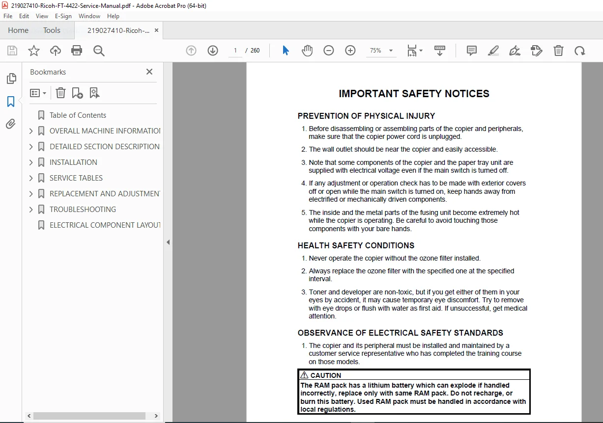
Official Ricoh service manual for FT-4422 analog copier (Condor series). Complete technical documentation covering installation, component replacement, troubleshooting, and copy quality adjustments. Essential resource for copier service technicians maintaining Ricoh FT-4422 office equipment. Includes detailed circuit diagrams, drum process control, optics system service, fusing unit procedures, service program mode operations, and comprehensive fault diagnosis with U-codes and error conditions.
Description
Ricoh FT-4422 Copier Service Manual Condor Repair Guide PDF DOWNLOAD
DESCRIPTION
Professional Service Manual for Ricoh FT-4422 Analog Copier
This official Ricoh FT-4422 service manual provides complete technical documentation for professional copier service technicians maintaining the FT-4422 analog copier (Condor series). This comprehensive Condor copier repair guide PDF contains factory procedures, circuit diagrams, component replacement instructions, service program mode operations, and detailed troubleshooting protocols essential for professional-level copier service.
FILE DETAILS
- Manual Name: FT-4422 Service Manual (Condor)
- Models Covered: Ricoh FT-4422 Analog Copier
- Series: Condor
- Model Variants: A110 and A173 configurations
- Manufacturer: Ricoh Company
- Format: Official Technical PDF
- Pages: 260 pages
- Quality: High-resolution factory original
- Language: English
- File Size: 3.9 MB
- Publication Date: 1996 (Updated 1997)
- Equipment Type: Desktop Analog Plain Paper Copier
COMPLETE MANUAL CONTENTS
This analog copier technical documentation is systematically organized into six comprehensive sections:
SECTION 1: OVERALL MACHINE INFORMATION
Machine Specifications
- Complete technical specifications
- Performance characteristics
- Operating parameters
- Environmental requirements
Copy Process Around the Drum
- Drum rotation and image formation cycle
- Charging process
- Exposure and latent image creation
- Development process
- Transfer and separation
- Cleaning cycle
- Erase sequence
Copy Process Control
- Process timing diagrams
- Control signal sequences
- Sensor coordination
- Motor control systems
Mechanical Component Layout
- Overall machine component positions
- Internal assembly locations
- Access points identification
- Maintenance area locations
Drive Layout
- Main motor drive train
- Clutch locations and functions
- Gear assembly diagrams
- Drive transmission paths
Electrical Component Descriptions
- Power supply systems
- Control boards
- Sensor locations and functions
- Motor and solenoid specifications
- Switch and relay descriptions
Major Differences Between A110 and A173 Models
- Configuration variations
- Component differences
- Specification changes
- Service procedure modifications
SECTION 2: DETAILED SECTION DESCRIPTIONS
1. DRUM SECTION
OPC Drum Characteristics
- Organic photoconductor specifications
- Drum surface properties
- Electrical characteristics
- Service life parameters
Drum Unit
- Drum assembly components
- Mounting structure
- Replacement procedures
- Handling precautions
2. DRUM CHARGE SECTION
Overview
- Charging system function
- Corona wire charging process
- Grid voltage control
Charge Corona Wire Cleaner Mechanism
- Automatic cleaning operation
- Cleaning cycle timing
- Maintenance requirements
Charge Corona Circuit
- High-voltage generation
- Current control
- Safety interlocks
Grid Voltage Correction (VR Correction)
- Automatic voltage adjustment
- Correction factors
- Calibration procedures
Grid Voltage Control
- Image Density Control – Automatic density adjustment
- Vr Detection – Surface potential measurement
- Toner Density Detection – Developer concentration monitoring
3. OPTICS SECTION
Overview
- Optical system layout
- Light path diagram
- Mirror positioning
- Lens system
Scanner Drive
- Scanner motor operation
- Wire drive mechanism
- Home position detection
- Speed control
Lens Drive
- Lens Drive Mechanism – Magnification control motor
- Lens Positioning – Home position and zoom positioning
4th and 5th Mirror Drive
- Drive System – Mirror movement mechanism
- Positioning – Alignment and home position
Automatic Image Density Detection
- ID sensor operation
- Density measurement cycle
- Automatic adjustment algorithm
Exposure Lamp Voltage Correction
- VL Correction – Lamp intensity adjustment
- Reproduction Ratio Correction – Zoom-dependent compensation
Exposure Lamp Voltage Control
- Base Lamp Voltage – Standard operating voltage
- Image Density Setting Factor – Manual ID mode adjustments
- VL Correction Factor – Automatic correction values
- Reproduction Ratio Correction Factor – Zoom compensation
Exposure Lamp Control
- On/off timing
- Warm-up sequence
- Safety monitoring
4. ERASE SECTION
Overview
- Erase lamp functions
- Residual charge removal
- Multi-zone erasing
Erase Types
- Lead Edge Erase – Front margin charge removal
- Side Erase – Lateral margin control
- Trail Edge Erase – Rear margin cleanup
- Editing Mode Erase – Special function erasure
- Erase During Detection Cycles – Calibration cycle erasure
5. DEVELOPMENT SECTION
Overview
- Two-component development system
- Magnetic brush development
- Developer mixing
Cross-Mixing
- Developer circulation
- Toner concentration uniformity
- Mixing mechanism
Development Bias for Image Density Control
- Base Bias Voltage Factor in Manual ID Control
- Base Bias Voltage Factor in Automatic ID Control
- Base Bias Voltage Adjustment Factor
- Vr Correction Factor – Process control compensation
Toner Saver Mode
- Reduced toner consumption operation
- Image quality trade-offs
- Activation conditions
Development Bias Circuit
- AC/DC bias generation
- Voltage control
- Current monitoring
SECTION 3: INSTALLATION
Installation Requirements
Environment
- Temperature and humidity specifications
- Ventilation requirements
- Electrical environment
- Physical space considerations
Machine Level
- Leveling procedures
- Tolerance specifications
- Leveling foot adjustments
Minimum Space Requirements
- Operational clearances
- Service access space
- Ventilation clearances
- User workspace
Power Requirements
- Voltage specifications
- Frequency requirements
- Current capacity
- Grounding requirements
Installation Procedure
Accessory Check
- Supplied components verification
- Optional equipment identification
- Documentation checklist
Copier Installation
- Unpacking procedures
- Protective material removal
- Initial setup steps
- Power connection
- Test copy procedures
Cassette Modification
- Paper cassette customization
- Size adjustment procedures
Optional Equipment Installation
- Key Counter Holder – Usage tracking installation
- Toner Overflow Sensor – Waste toner monitoring
- Pre-Transfer Lamp (PTL) – Image quality enhancement
- Optics Anti-Condensation Heater – Humidity control option
SECTION 4: SERVICE TABLES
Service Remarks
General Caution
- Safety precautions
- ESD protection
- Tool requirements
Component-Specific Cautions
- Drum and Drum Unit – Handling and storage
- Charge Corona – High-voltage safety
- Optics – Precision alignment requirements
- Development Unit – Developer handling
- Toner Supply – Contamination prevention
- Transfer and Separation – Wire maintenance
- Cleaning Unit – Blade replacement
- Fusing Unit – High-temperature hazards
- Paper Feed – Adjustment procedures
- Document Feeder – Optional equipment service
- Sorter – Optional equipment service
- Others – General maintenance notes
Service Program Mode
Service Program Mode Operation
- Access Procedure – Entering service mode
- Change Adjustment Values or Modes – Parameter modification
- Memory Reset Procedures – Clearing stored data
Service Program Mode Table
- Complete SP mode function listing
- Parameter descriptions
- Adjustment ranges
- Default values
SP-8 Sensor/Switch Data Check
- Real-time sensor monitoring
- Switch status verification
- Diagnostic data display
SP-9 Electrical Component Check
- Component testing procedures
- Output control
- Actuator verification
Misfeed Location Indicator
- Misfeed Indication – Error code display
- Misfeed Recovery – Clearing procedures
Service Tables
DIP Switches
- Switch locations
- Function descriptions
- Configuration settings
Variable Resistors
- VR locations
- Adjustment functions
- Setting procedures
Special Tools and Lubricants
- Required service tools
- Approved lubricants
- Application procedures
Preventive Maintenance Schedule
PM Table
- Maintenance intervals
- Component replacement schedules
- Cleaning requirements
Explanation of Regular PM
- Preventive maintenance task descriptions
- Inspection procedures
- Performance verification
Regular PM Procedure
- Step-by-step PM execution
- Checklist format
- Documentation requirements
SECTION 5: REPLACEMENT AND ADJUSTMENT
1. Exterior and Inner Covers
- Front Door – Removal and installation
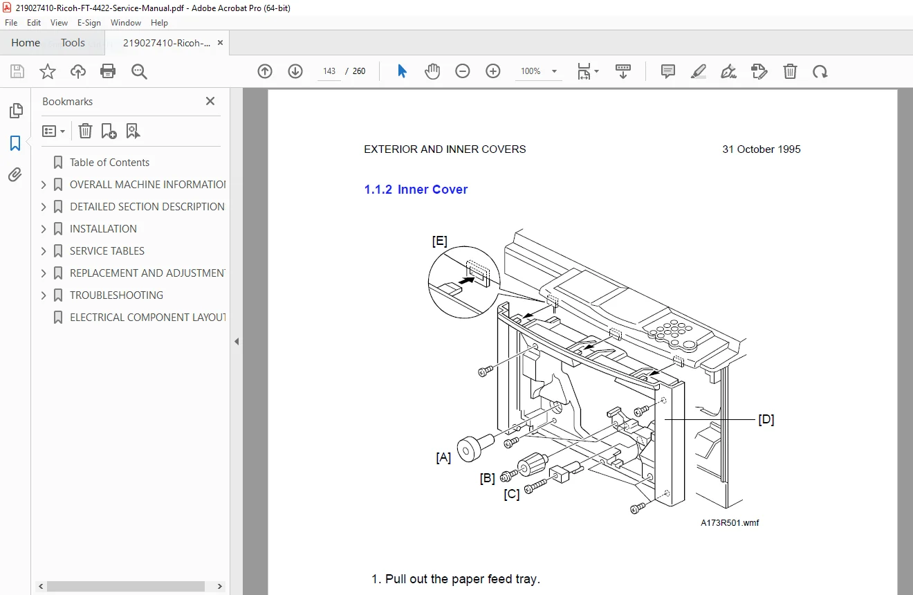
- Inner Cover – Access procedures
- Right Cover – Removal steps
- Rear Cover – Service access
- Left Covers – Multiple panel removal
- Upper Cover – Top access
- Operation Panel – Control panel service
2. Optics System
Component Replacement
- Exposure Glass – Platen glass replacement
- 1st Mirror – Scanner first surface mirror
- 2nd and 3rd Mirror – Scanner secondary mirrors
- 4th and 5th Mirror – Fixed mirror replacement
- Exposure Lamp – Halogen lamp replacement
- Optics Thermofuse – Over-temperature protection
- Scanner Drive Wire – Wire removal and installation procedures
- Scanner Motor – Drive motor replacement
- Lens Motor – Zoom drive motor
- Lens Drive Wire – Installation procedures
- 4th/5th Mirror Motor – Position adjustment motor
3. Development and Toner Supply
- Toner Supply Unit – Removal procedures
- Developer Replacement – Complete developer change
- Inlet Seal – Toner supply seal replacement
- Toner Supply Clutch – Electromagnetic clutch replacement
- Clutch Removal:
- 1st paper feed clutch
- 2nd paper feed clutch
- Relay roller clutch/Registration clutch
- Development Bias Voltage Adjustment (SP9-57) – Fine-tuning procedures
4. Cleaning System
- Cleaning Unit – Complete unit removal
- Cleaning Blade – Blade replacement procedures
- Used Toner Collection – Waste toner disposal
- Entrance Seal – Drum protection seal replacement
5. Paper Feed System
- 1st Paper Size Switch – Cassette size detection
- 1st Paper End Sensor – Paper presence detection
- Paper Feed Roller – Feed roller replacement
- Friction Pad – Separation pad replacement
- 2nd Paper Feed Roller – Secondary feed roller
- 2nd Paper End Sensor – Sensor replacement
- Registration Sensor/Registration Roller – Timing control components
- 1st Paper Feed Pressure Adjustment – Feed force calibration
6. Around the Drum
- Drum Replacement – Complete drum unit replacement
- ID Sensor – Image density sensor replacement
- Pick-Off Pawl – Paper separation device
- Quenching Lamp – Residual charge removal
- Erase Lamp – Edge erase lamp replacement
- Charge Corona Wire – Primary charging wire
- Charge Corona Grid – Grid electrode replacement
- Transfer/Separation Corona Wire – Transfer assembly wire
- Corona Current Adjustment:
- Charge corona current adjustment (SP9-2)
- Grid voltage adjustment (SP9-2)
- Transfer corona current adjustment (SP9-5)
- Separation corona current adjustment (SP9-8)
7. Fusing System
- Exit Unit – Output assembly removal
- Fusing Lamp – Heat lamp replacement
- Pressure Roller – Fusing pressure roller
- Hot Roller – Heated fusing roller replacement
- Fusing Thermistor and Thermofuse – Temperature sensors
- Fusing Pressure Adjustment – NIP pressure calibration
- Exhaust Blower Motors/Exit Sensor – Cooling and detection
8. Others
- Ozone Filter Replacement – Air quality maintenance
9. Copy Quality Adjustment
Comprehensive Quality Calibration
- Light Intensity Adjustment – Exposure lamp brightness
- Uneven Exposure Adjustment – Uniformity correction
- Bias Voltage Adjustment – Development voltage setting
- Toner Density Adjustment – Developer concentration
- Fixed Toner Supply Mode Selection – Manual vs. automatic
- Toner Supply Ratio Selection – Replenishment rate
- Vertical Magnification Adjustment – Scan direction scaling
- Horizontal Magnification Adjustment – Cross-scan scaling
- Focus Adjustment – Optical sharpness
- Leading Edge Erase Margin Adjustment – Top margin control
- Registration Adjustment – Image-to-paper alignment
- Side-to-Side Registration Adjustment – Lateral alignment
- 4th/5th Mirror Height Adjustment – Optical path calibration
SECTION 6: TROUBLESHOOTING
1. Copy Quality Problems
Systematic Fault Diagnosis
- Blank Copy (White Copy) – No image transferred
- Dirty Background – Excessive background toner
- Uneven Image Density – Inconsistent darkness
- Vertical Black Bands – Streaking defects
- Vertical Black Lines – Thin line defects
- Vertical White Lines or Bands–1 – Dull or blurred
- Vertical White Lines or Bands–2 – Thin, distinct
- Horizontal Black/White Lines – Cross-scan defects
- Jitter – Image instability
- Black Spots on Copy Image – Spot contamination
- Skewed (Optical) Copy Image – Misalignment
- Toner Density Too High – Overly dark copies
- Toner Density Too Low – Light, faded copies
- Toner Scattering – Loose toner contamination
- Unfused Copy Image – Poor fusing
- Paper Misfeed – Feed jam conditions
- DF Original Misfeed or Skew – Document feeder problems
2. U-Code Conditions
User-Level Alerts
- U1 – Right cover open
- U2 – Key counter not set
- U4 – Sorter open
- U6 – Drum protection sheet remaining
3. Service Call Conditions
Error Code Diagnostics
- Code #11 – Exposure lamp error
- Code #12 – Exposure lamp error (alternate)
- Code #13 – Zero cross signal error
- Code #21 – Scanner home position error
- Code #22 – Scanner home position error (alternate)
- Code #28 – Lens home position error
- Code #29 – Lens home position error (alternate)
- Code #2A – 4th/5th mirror home position error
- Code #2B – 4th/5th mirror home position error (alternate)
- Code #52 – Fusing lamp warm-up error
- Code #53 – Fusing lamp overheat
- Code #55 – Fusing thermistor open
- E70 – Toner overflow (in magnification indicator)
4. Electrical Component Defects
- Component-level troubleshooting
- Circuit testing procedures
- Board-level diagnostics
- Replacement criteria
WHO NEEDS THIS OFFICE COPIER TROUBLESHOOTING PROCEDURES MANUAL?
This Ricoh service program mode manual is essential for:
- Certified Copier Technicians – Authorized Ricoh service providers
- Office Equipment Service Centers – Independent repair facilities
- Corporate IT Maintenance Teams – In-house copier servicing
- Copy Center Technicians – High-volume operation maintenance
- Technical Training Instructors – Teaching copier repair
- Field Service Engineers – On-site repair specialists
- Remanufacturing Facilities – Copier refurbishment operations
KEY FEATURES OF THIS COPIER MAINTENANCE MANUAL
COMPREHENSIVE PROCESS COVERAGE
Detailed explanation of every copy process stage from drum charging through fusing, with control algorithms and timing diagrams.
SERVICE PROGRAM MODE MASTERY
Complete documentation of service program mode functions enabling advanced diagnostics, adjustments, and component testing.
COPY QUALITY OPTIMIZATION
Extensive copy quality adjustment procedures covering 13 different calibration operations for optimal output.
FACTORY-AUTHORIZED PROCEDURES
Official Ricoh engineering documentation ensures proper service techniques and maintains equipment reliability.
SYSTEMATIC TROUBLESHOOTING
Organized fault diagnosis covering 17 image quality problems, 4 U-codes, 13 service call conditions, plus electrical diagnostics.
DETAILED REPLACEMENT PROCEDURES
Step-by-step instructions for replacing every major component from drums to mirrors to corona wires.
MODEL VARIANT COVERAGE
Documentation includes differences between A110 and A173 model configurations.
TECHNICAL SPECIFICATIONS COVERED
| Feature | Details |
|---|---|
| Equipment Type | Analog Plain Paper Copier |
| Series | Condor (FT-4422) |
| Model Variants | A110, A173 |
| Imaging Technology | OPC Drum with Corona Charging |
| Copy Process | Carlson Process (Analog) |
| Development | Two-Component Magnetic Brush |
| Fusing | Hot Roller with Halogen Lamp |
ADVANCED SERVICE CAPABILITIES
Service Program Mode Functions:
- SP-8: Real-time sensor/switch monitoring
- SP-9: Component activation testing
- Parameter adjustment (voltage, timing, density)
- Memory reset procedures
- Diagnostic data display
- Counter management
Automatic Control Systems:
- Automatic Image Density (AID) control
- Grid voltage VR correction
- Exposure lamp VL correction
- Toner density detection and adjustment
- Development bias control
COPY QUALITY ADJUSTMENT CAPABILITIES
✓ Optical System Calibration – Focus, magnification (vertical/horizontal), mirror alignment
✓ Exposure Control – Light intensity, lamp voltage, uniformity correction
✓ Process Control – Charge voltage, transfer/separation current, development bias
✓ Image Registration – Leading edge, side-to-side, scan positioning
✓ Density Management – Manual and automatic image density, toner concentration
COMPONENT REPLACEMENT COVERAGE
Major Assemblies:
- Complete drum unit
- Fusing unit components
- Development unit
- Cleaning unit
- Scanner assembly
- Optical system components
Consumable Parts:
- Corona wires (charge, transfer, separation)
- Cleaning blade
- Feed rollers and friction pads
- Ozone filter
- Lamps (exposure, fusing, erase, quenching)
Wear Items:
- Drive wires
- Belts and clutches
- Sensors
- Seals and gaskets
- Thermistors and thermofuses
PREVENTIVE MAINTENANCE SCHEDULING
Complete PM program including:
- Regular inspection intervals
- Component replacement schedules
- Cleaning procedures
- Performance verification tests
- Documentation requirements
- PM counter management
OPTIONAL EQUIPMENT COVERED
- Key counter holder
- Toner overflow sensor
- Pre-transfer lamp (PTL)
- Optics anti-condensation heater
- Document feeder service
- Sorter service notes
WHAT YOU’LL RECEIVE
Upon purchase, you receive instant download access to the complete 260-page Ricoh FT-4422 copier service manual in PDF format. This is the identical technical documentation used by Ricoh-authorized service technicians worldwide, containing every procedure, adjustment, troubleshooting chart, and component specification needed for professional-level analog copier service and repair.
Stop struggling with incomplete service information—get the official factory manual with complete service program mode documentation and systematic troubleshooting procedures trusted by certified technicians worldwide. Download instantly and service your Ricoh FT-4422 with complete technical confidence today!