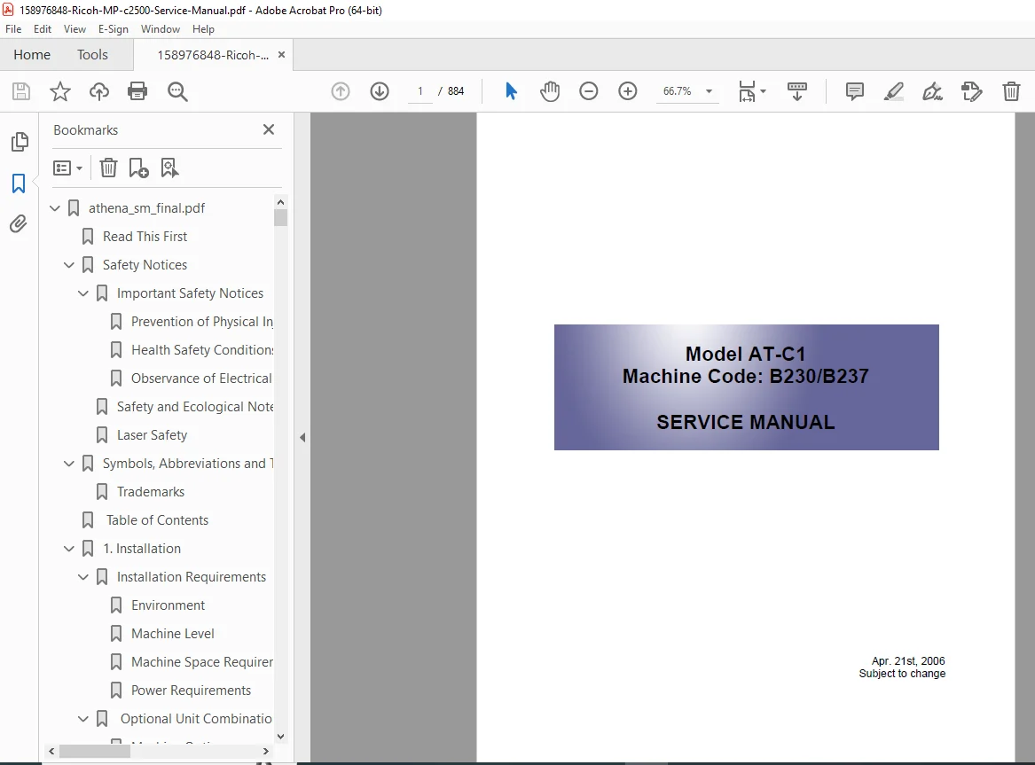
Ricoh MP C2500 / MP C3000 Service Manual PDF (Detailed Service & Repair Guide)
Original price was: $65.00.$19.95Current price is: $19.95.
This is the complete official Ricoh MP C2500 / MP C3000 Service Manual PDF, covering full disassembly, troubleshooting, SP mode tables, SC error codes, firmware installation, image adjustment procedures, mechanical/electrical operation theory, and wiring diagrams. This multi-hundred-page OEM manual is the primary service guide for all repair and maintenance tasks on the MP C2500 series.
Description
Ricoh MP C2500 / MP C3000 Service Manual PDF (Detailed Service & Repair Guide) – PDF DOWNLOAD
Description
This is the complete factory Ricoh MP C2500 / MP C3000 Service Manual, used by certified Ricoh technicians for professional servicing of the MP C2500 and MP C3000 color multifunction systems.
The manual provides extensive procedures for diagnostics, repair, maintenance, adjustments, and replacement for all major systems—PCU, development units, transfer mechanisms, fusing assembly, laser scanner unit, feed systems, duplexing, scanning, optics, finisher options, fax modules, and more.
It includes all SP mode items, all SC error codes, full wiring diagrams, parts location maps, jam detection logic, color calibration, print quality troubleshooting, and comprehensive electrical/mechanical operating theory.
This is the most complete technical reference for restoring, repairing, or maintaining the Ricoh MP C2500 / C3000 series.
Table of Contents
(Extracted and structured chapter-by-chapter for maximum clarity and SEO depth)
1. Safety & Introduction
General safety precautions
Laser safety information
Electrical safety
Handling static-sensitive components
Symbols and warning icons used throughout the manual
2. Product Overview
Model lineup (MP C2500, MP C3000)
System architecture
Part names & external views
Internal component locations
Engine specifications
Copying, printing, scanning, and faxing specifications
Option compatibility
ARDF, LCT, Finisher SR790, Booklet Finisher, Fax Unit 3000, HDD
3. Installation
Site/environment requirements
Unpacking procedure
Transport locks & shipping materials
Installation steps
Power supply & electrical conditions
Connecting optional units
Paper bank
LCT
Finisher / Booklet finisher
Fax / Printer controller
Driver installation & controller prep
Initial PCU setup
4. Preventive Maintenance
PM intervals for PCU, ITB, fuser, developer, fans
Maintenance counter reset
Cleaning/lubrication points
Life expectancy of parts
Color calibration
Registration adjustment procedures
Deodorizing filter replacement
5. Replacement & Adjustment
5.1 Exterior Covers
Front cover
Right/left side covers
Rear cover
Duplex cover
Bypass tray
5.2 Laser/Optics
Laser unit removal
Polygon mirror motor
LD pitch adjustments
Beam alignment
5.3 Imaging System (PCU)
Drum unit replacement
Charge roller
Cleaning blade
Toner supply system
ID sensor
5.4 Development Section
Cyan/Magenta/Yellow/Black development units
Developer replacement
ATC/Toner density sensor checks
5.5 Paper Feed / Transfer
Feed/pickup rollers
Registration roller
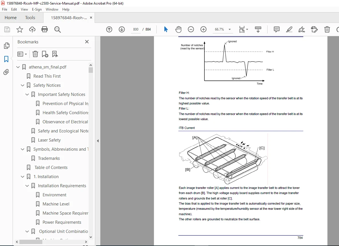
Intermediate Transfer Belt (ITB)
Secondary transfer roller
Duplex unit assemblies
Transport rollers & sensors
5.6 Fusing System
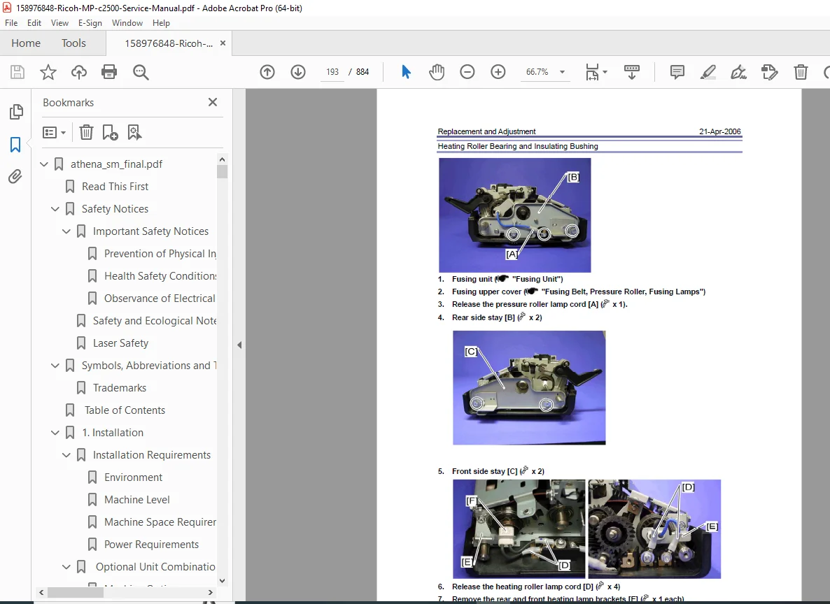
Fuser assembly
Fusing belt
Pressure roller
Thermistors
Lamps & thermostats
Temperature control circuits
5.7 Exit / Finisher
Exit roller
Shift motor
Stapler unit
Booklet folding mechanism
Finisher sensors & motors
5.8 Scanner & ADF
CCD unit
ADF feed rollers
Exposure glass cleaning
Lamp/inverter
6. Troubleshooting
6.1 Basic Flow
Systematic troubleshooting approach
Jam clearing logic
Mechanical vs. electrical fault isolation
6.2 SC Error Codes (Service Call Codes)
SC100–199: Laser/Optics
SC200–299: Motor errors
SC300–399: Image processing errors
SC400–499: Fusing temperature errors
SC500–599: Paper feed/transport
SC600–699: Hard disk/NVRAM/SD card
SC700–799: Finisher / ADF faults
6.3 Jams & Paper Feed Errors
Jam code definitions
Jam sensor checks
Registration timing checks
6.4 Image Quality Troubleshooting
Color misalignment
Light/dark prints
Vertical/horizontal streaks
Backgrounding
Spots, voids, repetitive defects
Repetitive defect chart (for PCU/drum/fuser/ITB)
6.5 Electrical Troubleshooting
Voltage checks
PSU and DC power checks
HV block diagnosis
Controller board problems
7. Service Mode (SP Mode)
7.1 Accessing SP Mode
Procedure to enter service mode
Passwords & protected functions
7.2 SP Categories
SP1xxx – Copier
SP2xxx – Image Process
SP3xxx – Laser/Optics
SP4xxx – Development
SP5xxx – Paper Feed
SP6xxx – Finisher / ADF
SP7xxx – Printer Controller
SP8xxx – Network / System Logs
SP9xxx – Memory & NVRAM functions
7.3 SP Test Patterns
Laser test pattern
Registration
Color alignment patterns
Halftone & gamma patterns
8. Printer, Scanner, Fax
Printer controller operations
PCL/PS/RPCS modes
Scanner operations
Fax unit installation and diagnostics
Address book & network configuration
9. Firmware & Software
Engine firmware
System firmware
Fax firmware
NVRAM backup/restore
Firmware update via SD card
10. Theory of Operation
10.1 Mechanical Theory
Pickup & feed timing
Image formation timing
Duplex cycle
Fusing temperature curve
Drive motor logic
10.2 Electrical Theory
Power supply sequences
HV generation
LD control
Controller signal flow
10.3 Image Process Theory
Color toner density control
Gamma correction
Registration control loop
ATC sensor operation
11. Wiring Diagrams
System wiring overview
BCU wiring
HV and LV wiring
PWB interconnections
Sensors, switches, motors
Finisher / ADF wiring diagrams
Network controller wiring
📁 File Details
| Field | Details |
|---|---|
| Manual Name | Ricoh MP C2500 / MP C3000 Service Manual |
| Models Covered | MP C2500, MP C3000 (all variants + options) |
| PDF Quality | High-quality, clear, text-searchable OEM PDF |
| Pages | 884 |
| Version | Complete factory edition |