
Royal Enfield Scram 411 Euro V Service Workshop Repair Manual
Original price was: $44.95.$26.95Current price is: $26.95.
Complete Royal Enfield Scram 411 Euro V service manual covering the 411 cc single-cylinder motorcycle with detailed maintenance, engine removal and overhaul, chassis service, fuel and EVAP systems, brakes and ABS, EMS diagnostics, electrical procedures, wiring diagrams, specifications, service limits, torque data, special tools, USB charger and swingarm procedures. 456-page PDF workshop reference.
Description
Royal Enfield Scram 411 Euro V Service Workshop Repair Manual
This Royal Enfield Scram 411 Euro V Service Workshop Repair Manual is a detailed technical reference for servicing, dismantling, inspecting, diagnosing and reassembling the Scram 411 motorcycle. The manual covers the motorcycle from routine periodic maintenance through substantial engine work, chassis servicing, fuel and emissions systems, braking and ABS, engine management and electrical diagnosis. Procedures are accompanied throughout by component illustrations, tool references, tightening values, cautions and inspection information.
The manual identifies the Scram 411 engine as a single-cylinder, 4-stroke SOHC unit with oil cooler and fuel injection, with a swept volume of 411 cc. It also provides specifications for the ignition system, five-speed constant-mesh transmission, chassis, suspension, brakes, tyres, fuel system, electrical equipment, dimensions and vehicle weights. This makes the Scram 411 Euro V workshop manual useful both when carrying out a specific repair and when checking the correct service data before work begins.
File Details
- Manual type: Service / workshop repair manual
- Brand and model: Royal Enfield Scram 411
- Emission coverage: Euro V, with Euro IV references where specifically included in procedures
- Language: English
- Page count: 456 pages
- File format: PDF
Technical Specifications and Maintenance Data
The specification section gives the key service data needed before repair work. Engine information includes the 78 mm bore, 86 mm stroke, 411 cc swept volume, 9.5:1 compression ratio, maximum power of 24.3 bhp (17.88 kW) at 6500 rpm and maximum torque of 32 N m at 4250 ± 250 rpm. The manual also identifies the BOSCH UR5CC spark plug, spark plug gap, engine oil grade, oil capacities, five transmission ratios, secondary drive ratio and 110-link drive chain.
Chassis information includes the half duplex split cradle frame, 41 mm telescopic front forks, linkage-type rear suspension, 300 mm front and 240 mm rear hydraulic disc brakes, tyre sizes and pressures, fuel tank information and vehicle dimensions. Electrical specifications cover the 12 V DC system, 12 volt 8 Ah VRLA battery, alternator, starter motor, lighting equipment and digital LCD instrument cluster.
The periodic maintenance section extends through service intervals up to 50,000 km and covers inspection, cleaning, lubrication, adjustment and replacement requirements for engine oil, oil filter, oil strainer, tappets, intake and oil cooler hoses, spark plug, fuel hose, air filter, accelerator and clutch cables, steering head bearings, fork oil, drive chain, battery terminals, brake fluid, brake hoses, brake pads, tyres, wheel bearings, swingarm bearings, suspension linkages and other service points. Additional instructions explain when more frequent service is needed for dusty, wet, off-road or severe operating conditions.
Engine Overhaul and Inspection
A major part of the Royal Enfield Scram 411 Euro V Service Workshop Repair Manual is devoted to engine work. The engine removal sequence begins with oil draining and progresses through the body panels, seat, battery, clutch cable, fuel tank, fuel pump connection, fuel hose, EVAP connections, throttle cable, throttle body, oxygen sensor connections, exhaust system, starter connections, gear linkage, final-drive sprocket, chain and cradle-frame mountings before the engine is removed from the main frame.
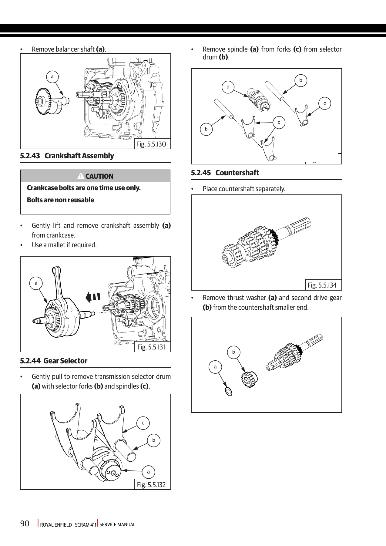
The engine dismantling section then covers the oil cooler, drain plug and strainer, oil filter, throttle body, injector, spark plug, engine oil temperature sensor, starter motor, breather, crankcase covers, gear-position sensor, clutch mechanism, balancer shaft, crankshaft gear, oil jet, oil pump, clutch assembly, shifter mechanism, final-drive sprocket, cylinder head cover, timing-chain tensioner, rocker components, camshaft and chain, stator, magneto rotor, starter clutch, cylinder head, valves and springs, cylinder barrel, piston, crankcases, balancer shaft, crankshaft, selector mechanism, countershaft and driveshaft.
Assembly procedures provide the corresponding sequences for transmission shafts, selector drum, crankshaft and balancer timing, crankcase closing, piston-ring orientation, cylinder barrel, valves, cylinder head, timing chain, magneto rotor, camshaft, rocker carrier and tappet adjustment. The manual specifies an inlet tappet clearance of 0.08 mm and exhaust clearance of 0.18 mm and includes numerous component-specific torque values and warnings concerning non-reusable fasteners, seals, gaskets and other one-time-use items.
The inspection section supports measurement-based engine assessment rather than simple visual dismantling. It includes cylinder-head and rocker-cover surface checks, camshaft journal and lobe limits, valve-guide and valve-stem measurements, valve-spring checks, cylinder bore and piston measurements, piston-ring gaps, connecting-rod small-end inspection, clutch plate and spring limits, shifter-fork measurements and selector-drum inspection.
Chassis, Wheels and Suspension Service
Chassis coverage extends well beyond basic body removal. Procedures include the air-filter box and element, clutch and throttle cables, cable free-play adjustment, handlebar assemblies, mirrors, switch modules, master cylinder, exhaust header, silencer and catalytic-converter components, rider and pillion footrests, side stand, mudguards, number-plate components, side panels, seat, grab rail and tank side panels.
The wheel section explains front and rear wheel removal, brake-disc removal, ABS toner-wheel handling, wheel bearings, spacers, sprocket carrier and cush rubbers. Inspection and reassembly procedures accompany the dismantling instructions, together with drive-chain free-play adjustment and precautions for protecting brake discs and ABS components. Suspension work is also included within the chassis coverage, and the manual contains a dedicated later procedure for removing and refitting the swingarm equipped with plastic spacers, including bearing sleeves, inner spacer, dust seals, lubrication quantities and spindle tightening information.
Fuel, EVAP and Euro V Systems
The fuel-system chapter covers the fuel tank, pump, level sensor, float, filter, associated seals and hose connections. Inspection procedures include fuel-pump and float checks, while the reassembly sequence addresses sealing, fuel connections and leakage checks after installation.
Euro V-specific EVAP information includes the charcoal canister and purge valve arrangement. The manual describes removal and installation of the Euro V canister, hose and connector inspection, purge-valve checks and an EVAP leak-test procedure. The leak test specifies pressurising the system to 20 kPa for 20 seconds, allowing 50 seconds for stabilisation and checking for a pressure drop of less than 300 Pa over five minutes.
Brakes, ABS and Diagnostic Coverage
Front and rear braking sections cover master cylinders, calipers, brake discs, pads and hydraulic servicing. ABS coverage includes wheel-speed sensors, toner rings, the ABS modulator and ABS diagnostic trouble codes, as well as preparation, reassembly and brake-bleeding procedures. The illustrated sequences show where precautions are required when working around caliper pistons, brake discs and wheel-speed components.
The Engine Management System section covers the ECU and related sensors and actuators, including fuel pump, injector, engine oil temperature sensor, HEGO/O2 sensor, purge valve, ignition coil, crank-position sensor, gear-position sensor, clutch switch, side-stand switch and starter-motor solenoid. Diagnostic actuator tests are described for the fuel pump, injector, ignition coil, O2 sensor heater, malfunction indicator lamp, idle air control valve, canister purge valve, secondary air injection solenoid and accessory relay. The manual also provides an EMS adaptation procedure where specified after changes involving EMS sensors or fuel type.
Electrical System and Wiring Diagrams
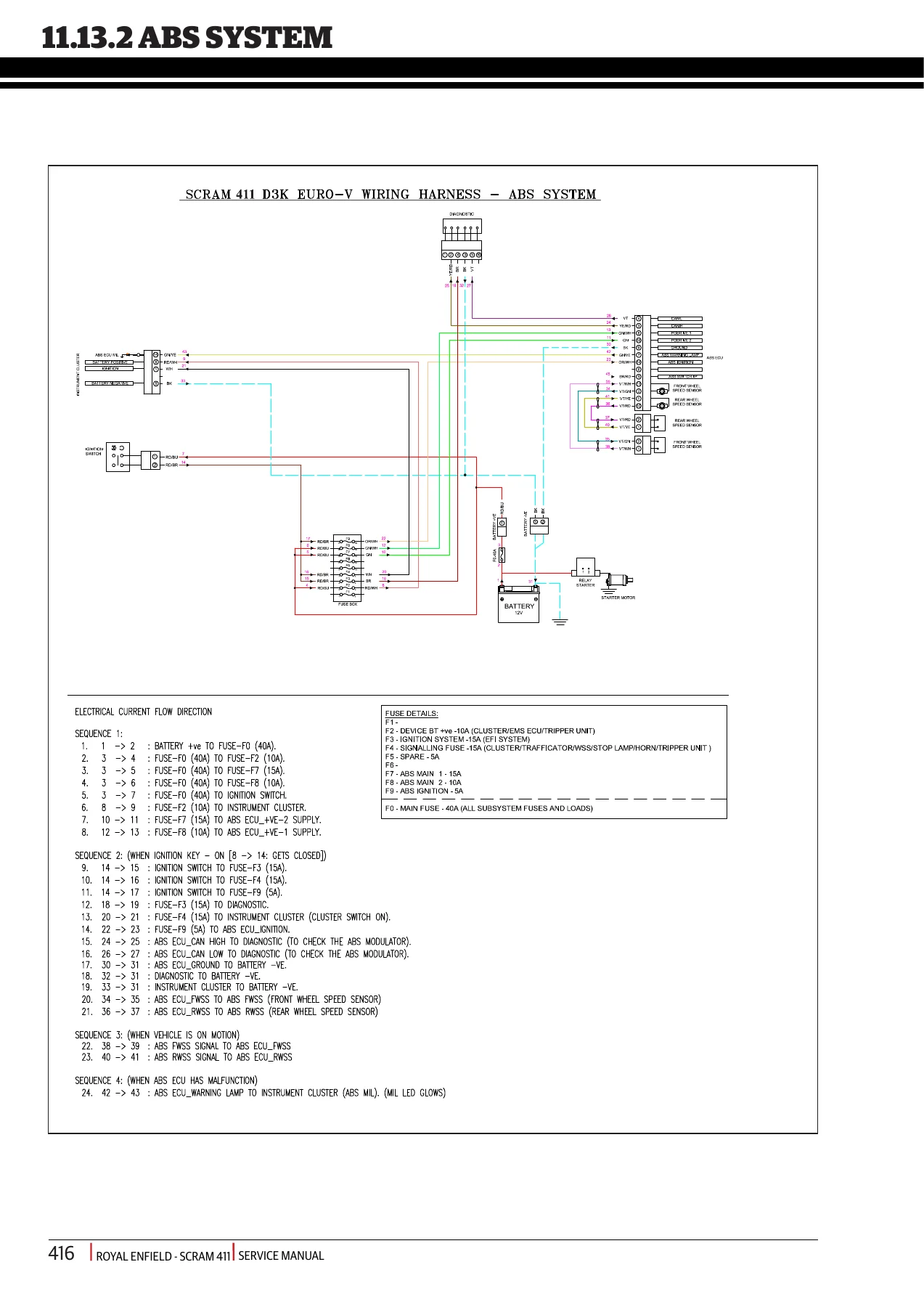
The electrical chapter covers headlamp and cluster dismantling, connectors behind the headlamp housing, tail lamp, brake-lamp connectors, trafficators, battery procedures and subsequent reassembly. This is followed by dedicated wiring diagrams for the main wiring harness, ABS system, charging system, cluster and Tripper unit, lighting system, brake signalling, horn signalling, trafficators and the starting/ignition EFI system.
The closing add-on material also includes removal and installation of the USB charger and its wiring kit, followed by the swingarm-with-plastic-spacer procedure. An index and technical glossary complete the manual and define abbreviations such as ABS, ECU, EMS, EFI, EVAP, HEGO, MAP, TPS, TDC and WSS.
Chapters Covered
- General Information
- Manual use, precautions and preparation prior to service
- Technical Specifications
- Engine, ignition, transmission, chassis, electrical system, dimensions and weights
- Periodical Maintenance Schedule
- Inspection, adjustment, lubrication, cleaning and replacement intervals
- General and Special Tools
- General tools, measurement tools and dedicated engine/vehicle special tools
- Engine
- Engine removal, dismantling, assembly, installation to frame and inspection
- Chassis
- Air filter box, control cables, handlebar, exhaust, footrests, stands, body components, wheels, suspension and troubleshooting
- Fuel System
- Fuel tank, pump, level sensor, float, filter, hoses and connections
- Evaporative Emission Control System
- Canister, purge valve, hoses, inspection and leak testing
- Brakes and ABS
- Front and rear brakes, ABS components, diagnostics and brake bleeding
- Engine Management System
- ECU, sensors, switches, actuators and diagnostic test procedures
- Electrical System
- Lighting, instrument cluster, battery, connectors and electrical component servicing
- Wiring Diagrams
- Main harness, ABS, charging, cluster/Tripper, lighting, signalling and EFI starting/ignition circuits
- Exclusive Addon Parts – USB Charger
- USB charger and wiring-kit removal and installation
- Swingarm with Plastic Spacer
- Swingarm removal, spacer and seal replacement, lubrication and refitment
- Index and Glossary
Taken together, these chapters provide a technician with the information needed to approach routine Scram 411 maintenance, component removal, major engine dismantling and rebuilding, measured inspection, chassis work, brake and ABS servicing, fuel and emissions work, EMS diagnosis and electrical troubleshooting using the procedures and specifications presented for this motorcycle.
Service and Repair Your Scram 411 with the Correct Procedures
The Royal Enfield Scram 411 Euro V Service Workshop Repair Manual supports work ranging from periodic servicing and adjustments to engine removal and overhaul, clutch and transmission repair, wheel and suspension service, braking and ABS work, fuel-system repairs, EVAP checks, EMS diagnostics and electrical troubleshooting. Detailed sequences, specified tools, inspection limits, torque values, adjustment data and wiring diagrams help reduce guesswork when dismantling, measuring and rebuilding components.
IMAGES PREVIEW
Using the procedures and specifications supplied for the Scram 411 matters when fastener torque, component orientation, service limits, clearances, cable adjustment, sensor handling or assembly order can affect the reliability and safety of the finished repair. This manual is delivered as an instant PDF download after purchase, with no physical book and no shipping delay. Save it to a computer, tablet or phone for convenient workshop reference, and print the pages you need for the job at hand.
Reviews
There are no reviews yet.