Trusted Business
Verified & Licensed
Virus Free Files
100% Safe Downloads
Secure Payment
SSL Protected
Instant Delivery
Available Immediately
Skyjack SJ61 T+, SJ66 T+ Telescopic Booms Service Manual 229039AAA – PDF DOWNLOAD
$28.95
Skyjack SJ61 T+, SJ66 T+ Telescopic Booms Service Manual 229039AAA – PDF DOWNLOAD
SJ61 T+: A401 000 001 – A401 999 999
SJ66 T+: A401 000 001 – A401 999 999
Instant PDF Download
Available immediately
Save to Your Device
Download & keep forever
Antivirus Scanned
100% virus-free
Trusted Worldwide
175,000+ customers
Description
Skyjack SJ61 T+, SJ66 T+ Telescopic Booms Service Manual 229039AAA – PDF DOWNLOAD
FILE DETAILS:
Skyjack SJ61 T+, SJ66 T+ Telescopic Booms Service Manual 229039AAA – PDF DOWNLOAD
Language : English
Pages : 239
Downloadable : Yes
File Type : PDF
IMAGES PREVIEW OF THE MANUAL:
DESCRIPTION:
Skyjack SJ61 T+, SJ66 T+ Telescopic Booms Service Manual 229039AAA – PDF DOWNLOAD
SJ61 T+: A401 000 001 – A401 999 999
SJ66 T+: A401 000 001 – A401 999 999
Read and Heed:
Skyjack is continuously improving and expanding product features on its equipment, therefore,
specifications and dimensions are subject to change without notice.
Skyjack is continuously improving and expanding product features on its equipment, therefore,
specifications and dimensions are subject to change without notice.
1.1-1 Mobile Elevating Work Platform (MEWP) Definition
A mobile device that has a positionable platform supported from ground level by a structure.
A mobile device that has a positionable platform supported from ground level by a structure.
1.1-2 Purpose of Equipment
The Skyjack Telescopic Boom Series MEWPs are designed to transport and raise personnel, tools and
materials to overhead work areas.
The Skyjack Telescopic Boom Series MEWPs are designed to transport and raise personnel, tools and
materials to overhead work areas.
1.1-3 Use of Equipment
The MEWP is a highly maneuverable, mobile work station. Work platform elevation and elevated
driving must only be done on a firm, level surface.
The MEWP is a highly maneuverable, mobile work station. Work platform elevation and elevated
driving must only be done on a firm, level surface.
1.1-4 Manual
Operating Manual: The operating manual is considered a fundamental part of the MEWP. It is a very
important way to communicate necessary safety information to users and operators. A complete
and legible copy of this manual must be kept in the provided weather-resistant storage compartment
on the MEWP at all times.
Service & Maintenance:
- The purpose of this is to provide the customer with the servicing and
maintenance procedures essential for the promotion of proper machine operation for its intended
purpose. - All information in this manual should be read and understood before any attempt is made to service
the machine.
1.1-5 Service Policy and Warranty
Skyjack warrants each new product to be free of defective parts and workmanship for the first 2
years or 3000 hours, whichever occurs first. Any defective part will be replaced or repaired by
your local Skyjackdealer at no charge for parts or labor.
In addition, all products have a 5 year structural warranty. Contact the Skyjack Service Department
for warranty statement extensions or exclusions.
1.1-6 Operator Safety Reminders, Warnings and Precautions
Operator safety is Skyjack’s priority. The operator should comply with all applicable
safety-related reminders, warnings and precautions found in the Operating Manual. They should be
read and understood completely before operating the MEWP.
Operator safety is Skyjack’s priority. The operator should comply with all applicable
safety-related reminders, warnings and precautions found in the Operating Manual. They should be
read and understood completely before operating the MEWP.
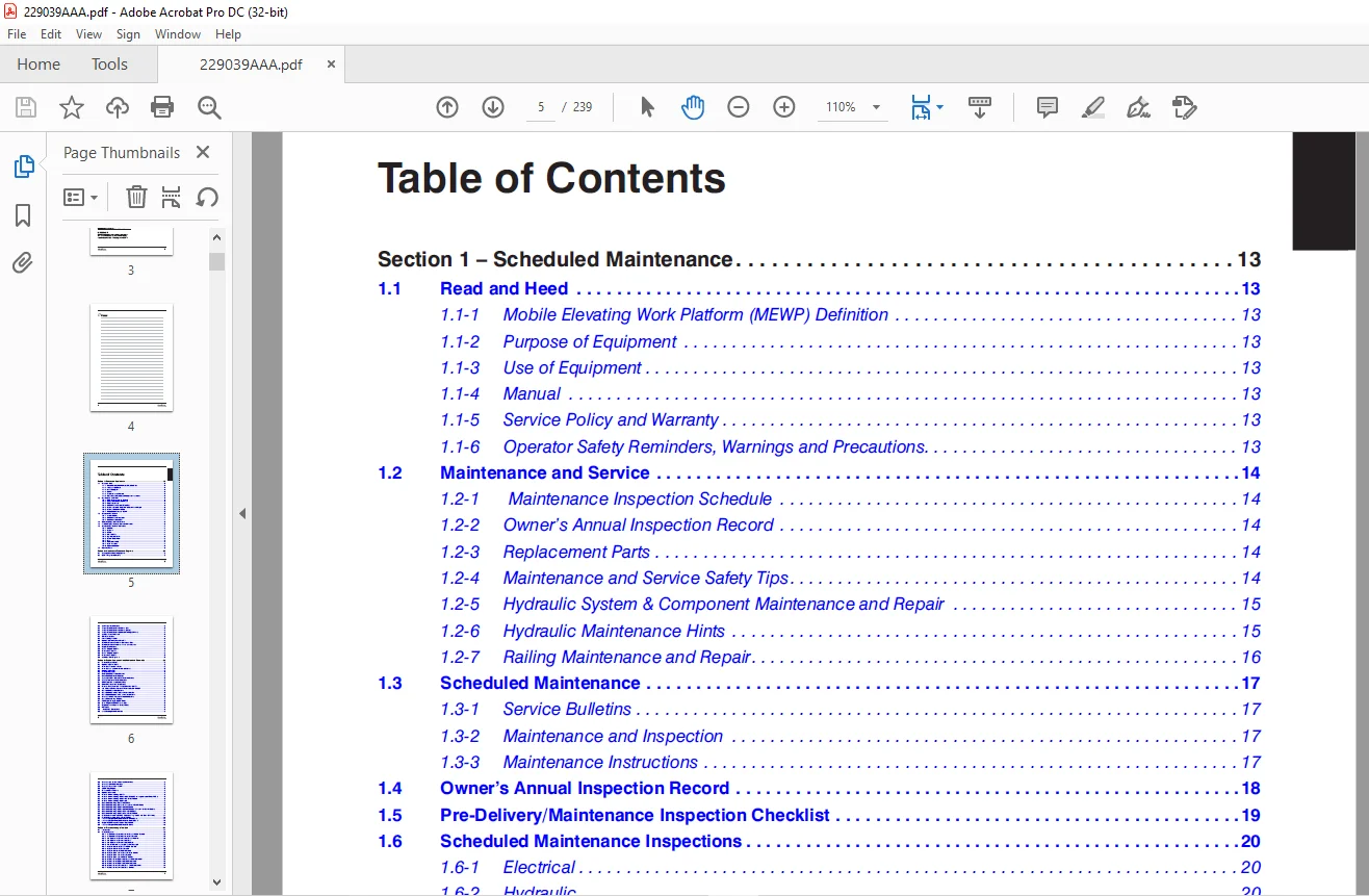
TABLE OF CONTENTS:
Skyjack SJ61 T+, SJ66 T+ Telescopic Booms Service Manual 229039AAA – PDF DOWNLOAD
Section 1 – Scheduled Maintenance............................................................................... 13
	1.1  Read and Heed.......................................................................................... 13
		1.1-1 Mobile Elevating Work Platform (MEWP) Definition.................................................. 13
		1.1-2 Purpose of Equipment.............................................................................. 13
		1.1-3 Use of Equipment.................................................................................. 13
		1.1-4 Manual............................................................................................ 13
		1.1-5 Service Policy and Warranty....................................................................... 13
		1.1-6 Operator Safety Reminders, Warnings and Precautions............................................... 13
	1.2  Maintenance and Service................................................................................ 14
		1.2-1  Maintenance Inspection Schedule.................................................................. 14
		1.2-2 Owner’s Annual Inspection Record.................................................................. 14
		1.2-3 Replacement Parts................................................................................. 14
		1.2-4 Maintenance and Service Safety Tips............................................................... 14
		1.2-5 Hydraulic System & Component Maintenance and Repair............................................... 15
		1.2-6 Hydraulic Maintenance Hints....................................................................... 15
		1.2-7 Railing Maintenance and Repair.................................................................... 16
	1.3  Scheduled Maintenance.................................................................................. 17
		1.3-1 Service Bulletins................................................................................. 17
		1.3-2 Maintenance and Inspection........................................................................ 17
		1.3-3 Maintenance Instructions.......................................................................... 17
	1.4  Owner’s Annual Inspection Record....................................................................... 18
	1.5  Pre-Delivery/Maintenance Inspection Checklist.......................................................... 19
	1.6  Scheduled Maintenance Inspections...................................................................... 20
		1.6-1 Electrical........................................................................................ 20
		1.6-2 Hydraulic......................................................................................... 20
		1.6-3 Labels (B)........................................................................................ 20
		1.6-4 Limit switches (B)................................................................................ 20
		1.6-5 Engine Compartment................................................................................ 21
		1.6-6 Control Compartment............................................................................... 24
		1.6-7 Base.............................................................................................. 26
		1.6-8 Platform Assembly ................................................................................ 28
		1.6-9 Boom Assembly..................................................................................... 29
		1.6-10 Optional equipment (B)........................................................................... 31
	1.7  Function Tests......................................................................................... 32
Section 2 – Maintenance Tables and Diagrams..................................................................... 33
	2.1  Standard Hose Numbering System......................................................................... 33
	2.2  MEWP Torque Specifications............................................................................. 35
	2.3  Axle Torque Specifications............................................................................. 36
	2.4  Torque Specifications for Fasteners (US)............................................................... 37
	2.5  Torque Specifications for Fasteners (Metric)........................................................... 38
	2.6  Torque Specifications for Hydraulic Couplings & Hoses.................................................. 39
	2.7  Axle Maintenance Intervals............................................................................. 40
	2.8  Tire Specifications.................................................................................... 41
	2.9  Floor Loading Pressure................................................................................. 42
	2.10  Hydraulic Specifications & Gear Oil................................................................... 43
	2.11  Specifications and Features - Dimensional Data........................................................ 44
	2.12  Specifications and Features - Performance & Speeds.................................................... 45
	2.13  Engine Specifications................................................................................. 46
	2.14  Reach Diagram - SJ61 T+............................................................................... 47
	2.15  Dimensions - SJ61 T+.................................................................................. 48
	2.16  Reach Diagram - SJ66 T+............................................................................... 49
	2.17  Dimensions - SJ66 T+.................................................................................. 50
	2.18  Axle Oscillation Diagrams............................................................................. 51
Section 3 – System Component Identification and Schematics...................................................... 53
	3.1  Electrical Symbol Chart................................................................................ 54
	3.2  Hydraulic Symbol Chart................................................................................. 55
	3.3  Wire Number and Color Code............................................................................. 56
	3.4  Wire Numbers and Color Codes - Additional.............................................................. 57
	3.5  Hydraulic Parts List................................................................................... 58
	3.6  Electrical Parts List.................................................................................. 61
	3.7  Rotary Manifold Port Identification.................................................................... 65
	3.8  Brake Manifold Port Identification..................................................................... 66
	3.9  System and Drive Pumps and Port Identifications........................................................ 67
	3.10  System Pump and Port Identifications.................................................................. 68
	3.11  Drive Pump and Port Identifications................................................................... 69
	3.12  Drive Motors and Port Identifications................................................................. 70
	3.13  Platform Rotate Valve and Port Identification - SJ61 T+............................................... 71
	3.14  Jib & Platform Rotate Valve and Port Identification - SJ66 T+......................................... 72
	3.15  Main Manifold Port Identification..................................................................... 73
	3.16  Main Manifold Electrical Component Identification..................................................... 74
	3.17  Main Manifold Hydraulic Component Identification...................................................... 75
	3.18  Generator Control Valves and Port Indentifcations..................................................... 76
	3.19  Main Harness Wiring Diagram........................................................................... 77
	3.20  ECU Engine Wiring Diagram - Deutz..................................................................... 78
	3.21  Glow Plug and EGR Harnesses - Deutz................................................................... 79
	3.22  Engine Interface Harness - Deutz TD2.9L............................................................... 80
	3.23  Harnesses............................................................................................. 81
	3.24   Limit Switch Connections............................................................................. 82
	3.25  Load Sensing Cable Connection......................................................................... 83
	3.26  Generator and Oil Cooler Harness Connections.......................................................... 84
	3.27  Generator Wire Kit Connections........................................................................ 85
	3.28  Generator Connection - 12 kW.......................................................................... 86
	3.29  SGE Wiring Diagram.................................................................................... 87
	3.30  Differential Lock Harness............................................................................. 88
	3.31  Hydraulic Schematic................................................................................... 89
	3.32  Platform Controls Wiring - SJ61 T+.................................................................... 90
	3.33  Platform Controls Wiring - SJ66 T+ ANSI/CSA & CE - all engines except Deutz TCD2.2.................... 91
	3.34  Platform Controls Wiring - SJ66 T+ CE - Deutz TCD2.2.................................................. 92
	3.35  Platform Controls Wiring - SJ66 T+ AS................................................................. 93
	3.36  Base Controls Wiring - SJ61 T+ ANSI/CSA............................................................... 94
	3.37  Base Controls Wiring - SJ61 T+ with Positive Air Shut-Off Option...................................... 95
	3.38  Base Controls Wiring - SJ66 T+ ANSI/CSA & AS.......................................................... 96
	3.39  Base Controls Wiring - SJ66 T+ ANSI/CSA & AS with Positive Air Shut-Off Option........................ 97
	3.40  Base Controls Wiring - SJ66 T+ CE with Deutz D2011.................................................... 98
	3.41  Base Controls Wiring - SJ66 T+ CE with Deutz TCD2.2................................................... 99
	3.42  Electrical Schematic - ANSI/CSA & AS with all engines, CE with Deutz D2011 only.......................100
	3.43  Electrical Schematic - CE with Deutz TCD2.2...........................................................101
	3.44  Interface & Engine Electrical Schematic - Deutz TD2.9L................................................102
	3.45  Interface & Engine Electrical Schematic - Deutz TCD2.2................................................103
	3.46  Engine OEM Harness Schematic - Deutz TCD2.2...........................................................104
	3.47  Interface & Engine Electrical Schematic - Kubota......................................................105
Section 4 – Troubleshooting Information.........................................................................107
	4.1  Introduction...........................................................................................107
	4.2  Electrical System......................................................................................108
		4.2-1 All Controls are Inoperative from the Base or Platform Console....................................108
		4.2-2 All Controls are Inoperative from the Base Console................................................110
		4.2-3 The Engine will not Crank from the Base or Platform...............................................110
		4.2-4 The Engine will not Crank from the Base...........................................................111
		4.2-5 The Engine will not Crank from the Platform.......................................................111
		4.2-6 The Boom Controls are Inoperative (Drive Operates)................................................111
		4.2-7 No Boom Up from the Base or Platform Controls.....................................................112
		4.2-8 No Boom Up from the Base Console..................................................................112
		4.2-9 No Boom Up from the Platform Console..............................................................112
		4.2-10 No Boom Down from the Base or Platform Consoles..................................................112
		4.2-11 No Boom Down from the Base Console...............................................................113
		4.2-12 No Boom Down from the Platform Console...........................................................113
		4.2-13 No Turret Rotate Right from the Base or Platform Consoles........................................113
		4.2-14 No Turret Rotate Right from the Platform Console.................................................113
		4.2-15 No Turret Rotate Right from the Platform Console.................................................114
		4.2-16 No Turret Rotate Left from the Base or Platform Consoles.........................................114
		4.2-17 No Turret Rotate Left from the Base Console......................................................114
		4.2-18 No Turret Rotate Left from the Platform Console..................................................114
		4.2-19 No Telescope Out from the Base or Platform Consoles..............................................115
		4.2-20 No Telescope Out from the Base Console...........................................................115
		4.2-21 No Telescope Out from the Platform Console.......................................................115
		4.2-22 No Telescope In from the Base or Platform Consoles...............................................116
		4.2-23 No Telescope In from the Base Console............................................................116
		4.2-24 No Telescope In from the Platform Console........................................................116
		4.2-25 No Platform Level Up from the Base or Platform Consoles..........................................116
		4.2-26 No Platform Level Up from the Base Console.......................................................117
		4.2-27 No Platform Level Up from the Platform Console...................................................117
		4.2-28 No Platform Level Down from the Base or Platform Consoles........................................117
		4.2-29 No Platform Level Down from the Base Console.....................................................117
		4.2-30 No Platform Level Down from the Platform Console.................................................118
		4.2-31 No Platform Rotate or Jib Functions from the Base or Platform Consoles...........................118
		4.2-32 No Platform Rotate Right from the Base or Platform Consoles......................................118
		4.2-33 No Platform Rotate Right from Base Console.......................................................119
		4.2-34 No Platform Rotate Right from the Platform Console...............................................119
		4.2-35 No Platform Rotate Left from the Base of Platform Consoles.......................................119
		4.2-36 No Platform Rotate Left from the Base Console....................................................119
		4.2-37 No Platform Rotate Left from the Platform Console................................................120
		4.2-38 No Jib Up from the Base or Platform Consoles.....................................................120
		4.2-39 No Jib Up from the Base Console..................................................................120
		4.2-40 No Jib Up from the Platform Console..............................................................120
		4.2-41 No Jib Down from the Base or Platform Consoles...................................................121
		4.2-42 No Jib Down from the Base Console................................................................121
		4.2-43 No Jib Down from the Platform Console............................................................121
		4.2-44 No Drive or Steer Functions......................................................................121
		4.2-45 No Forward or Reverse Drive......................................................................122
		4.2-46 No Forward Drive.................................................................................122
		4.2-47 No Reverse Drive.................................................................................122
		4.2-48 The Brake will not Release.......................................................................123
		4.2-49 No Left Steer....................................................................................123
		4.2-50 No Right Steer...................................................................................124
		4.2-51 The Directon Sensing is Inoperative..............................................................124
		4.2-52 The Load Sense Indicates Overload or Overload Warning with the Platform Empty or Below Weight....124
		4.2-53 The Overload Indicator Light does not Turn On when the Platform is Overloaded....................125
		4.2-54 The Audible Alarm does not Turn On with the Platform Overloaded..................................125
	4.3  Hydraulic System.......................................................................................126
		4.3-1 All Controls are Inoperative......................................................................126
		4.3-2 All Boom Functions are Inoperative................................................................126
		4.3-3 No Main Boom Up...................................................................................126
		4.3-4 No Main Boom Down.................................................................................127
		4.3-5 No Turret Rotate..................................................................................127
		4.3-6 No Boom Extend....................................................................................128
		4.3-7 No Boom Retract...................................................................................129
		4.3-8 No Jib Up.........................................................................................129
		4.3-9 No Jib Down.......................................................................................130
		4.3-10 No Platform Rotation.............................................................................130
		4.3-11 Platform will not Level..........................................................................131
		4.3-12 Brake will not Release...........................................................................132
		4.3-13 Brake will not Engage............................................................................132
		4.3-14 No Drive.........................................................................................132
		4.3-15 Differential Lock will not Engage................................................................133
		4.3-16 No High Speed Drive..............................................................................133
		4.3-17 No Steer.........................................................................................133
		4.3-18 Axle Will Not Oscillate..........................................................................134
		4.3-19 Axle Will Not Lock...............................................................................134
Section 5 – Procedures..........................................................................................135
	5.1  General................................................................................................135
		5.1-1 Safety and Workmanship............................................................................135
	5.2  Platform...............................................................................................136
		5.2-1 Human Machine Interface (HMI).....................................................................136
		5.2-2 User Interface Keys...............................................................................136
		5.2-3 OCM Character Functions Charts....................................................................137
		5.2-4 OCM Pin Reference.................................................................................138
		5.2-5 Fly Boom Switch Voltage References................................................................144
		5.2-6 Fly Boom Switch Voltage References................................................................145
		5.2-7 Platform Controller Voltage References............................................................146
	5.3  Boom...................................................................................................147
		5.3-1 Check Wear Pads...................................................................................147
		5.3-2 Shim Wear Pads....................................................................................147
		5.3-3 Cable Carrier Repair..............................................................................147
		5.3-4 Rotary Actuator Bolt Torque Procedure.............................................................147
		5.3-5 Boom Section Wear Pad Replacement.................................................................148
		5.3-6 Platform and Jib Boom Removal.....................................................................149
		5.3-7 Platform Removal (no Jib Boom)....................................................................151
		5.3-8 Operating Machine Functions from the Base Controls................................................153
		5.3-9 Fly Boom Section Removal..........................................................................154
		5.3-10 Mid Boom Section Removal.........................................................................155
		5.3-11 Mid Boom Section Installation....................................................................157
		5.3-12 Fly Boom Section Installation....................................................................158
		5.3-13 Platform and Jib Boom Installation...............................................................158
		5.3-14 Platform Installation (no Jib Boom)..............................................................159
		5.3-15 Platform Control Console Connection..............................................................160
		5.3-16 Inspection and Replacement of Extension Cylinder and Boom Cables.................................160
		5.3-17 Extension Cylinder and Cable Assembly Removal....................................................161
		5.3-18 Extension Cylinder and Cable Assembly Installation...............................................164
		5.3-19 Proper Wire Rope Tension.........................................................................167
		5.3-20 Wire Rope Inspection.............................................................................168
	5.4  Turret.................................................................................................169
		5.4-1 Check and Replace the High Pressure Filter........................................................169
		5.4-2 Adjust the Turret Rotation Gear Backlash..........................................................169
		5.4-3 Check the Swing Drive Oil.........................................................................170
		5.4-4 Change the Swing Drive Oil........................................................................170
		5.4-5 Battery Replacement...............................................................................171
		5.4-6 Turret Rotation Gear Bolt Torque Sequence.........................................................171
		5.4-7 Electronic Tilt Switch Setup Procedure............................................................172
		5.4-8 Check the Rotation Bearing for Axial Wear.........................................................174
	5.5  Deutz Diesel Engines...................................................................................175
		5.5-1 Replace the Engine Oil and Filter.................................................................175
		5.5-2 Replace the Fuel Filter...........................................................................176
		5.5-3 Replace the Air Filter............................................................................176
		5.5-4 Check the Engine Belt.............................................................................176
		5.5-5 Check the Oil Cooler (Deutz D2011 only)...........................................................176
		5.5-6 Deutz TD2.9L Fault Codes..........................................................................177
		5.5-7 Deutz TCD2.2 Diagnoses and Error Codes............................................................197
	5.6  Kubota WG2503 Dual Fuel Engine.........................................................................208
		5.6-1 Engine Parameter Display (KAntrak 1700)...........................................................208
		5.6-2 Diagnostic Trouble Codes..........................................................................209
		5.6-3 Diagnostic Trouble Codes..........................................................................210
		5.6-4 Diagnostic Trouble Codes..........................................................................211
		5.6-5 Diagnostic Trouble Codes..........................................................................212
		5.6-6 Diagnostic Trouble Codes..........................................................................213
		5.6-7 ECU Pin Reference Chart - Kubota WG2503...........................................................214
		5.6-8 Fuse Box - Kubota WG2503..........................................................................215
		5.6-9 MAP Sensor - Kubota WG2503........................................................................216
		5.6-10 IAT Sensor - Kubota WG2503.......................................................................216
		5.6-11 ECT - Kubota WG2503..............................................................................217
		5.6-12 TPS & Engine Speed - Kubota WG2503...............................................................217
		5.6-13 Fuel Temperature Sensor - Kubota WG2503..........................................................218
		5.6-14 Oil Pressure Sensor - Kubota WG2503..............................................................218
	5.7  Hydraulic Tank.........................................................................................219
		5.7-1 Hydraulic Oil Replacement.........................................................................219
		5.7-2 Hydraulic Filter Replacement......................................................................219
	5.8  Manifold and Hydraulic Pumps...........................................................................220
		5.8-1 Hydraulic Brake Pressure Adjustment...............................................................220
		5.8-2 Hydraulic Standby Pressure Adjustment.............................................................221
		5.8-3 Hydraulic High Pressure Adjustment................................................................222
		5.8-4 Hydraulic System Relief Valve Adjustment..........................................................223
		5.8-5 Turret Rotate Relief Valve Adjustment.............................................................224
		5.8-6 Platform Level Relief Valve Adjustment............................................................224
		5.8-7 Fly Boom Relief Valve Adjustment..................................................................225
		5.8-8 Test Charge Pump Pressure on Drive Pump...........................................................225
		5.8-9 Test Forward Drive Pressure on Drive Pump.........................................................226
		5.8-10 Test Reverse Drive Pressure on Drive Pump........................................................226
	5.9  Axles..................................................................................................227
		5.9-1 Change the Oil in the Axles ......................................................................227
		5.9-2 Check the Oil Level in the Torque Hubs............................................................227
		5.9-3 Change the Oil in the Torque Hubs.................................................................227
		5.9-4 Check the Oil Level in the Axle Gearbox...........................................................228
		5.9-5 Change the Oil in the Axle Gearbox................................................................228
		5.9-6 Oscillating Cylinder Bolt Replacement.............................................................229
		5.9-7 Oscillating Cylinder Replacement..................................................................229
		5.9-8 Bleed the Oscillating Axle Cylinders..............................................................231
		5.9-9 Test the Oscillating Axle Cylinders...............................................................231
		5.9-10 Pin Brake Adjustments............................................................................232
		5.9-11 Brake Inspection.................................................................................233
	5.10  Grease Points.........................................................................................234
		5.10-1 Grease the Turret Ring Gear......................................................................234
		5.10-2 Grease the Turret Swing Drive....................................................................234
		5.10-3 Grease the Axles.................................................................................235
		5.10-4 Grease the Drive Shaft...........................................................................235
	5.11  Options...............................................................................................236
		5.11-1 Generator Troubleshooting........................................................................236
		5.11-2 Generator Frequency/Voltage Check & Adjustment...................................................237
Contact us: [email protected]
https://vimeo.com/876839071?share=copy
PLEASE NOTE:
- This is the same manual used by the dealers to diagnose and troubleshoot your vehicle
- You will be directed to the download page as soon as the purchase is completed. The whole payment and downloading process will take anywhere between 2-5 minutes
- Need any other service / repair / parts manual, please feel free to contact [email protected] . We still have 50,000 manuals unlisted
S.V