
Skyjack SJ85 AJ Articulating Boom Lift Parts Manual 229037AHA PDF
Original price was: $39.95.$23.95Current price is: $23.95.
Complete 310-page illustrated parts manual for the Skyjack SJ85 AJ articulating boom, publication 229037AHA. Exploded assembly drawings and Skyjack part numbers for the platform, boom, cylinders, turret, chassis, axles, engines, harnesses, hoses, options and labels.
Description
Skyjack SJ85 AJ Parts Manual – Publication 229037AHA
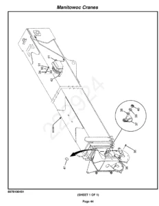
This is the illustrated parts manual for the SJ85 AJ articulating boom, issued under Skyjack document number 229037AHA and carrying a 2023-2024 edition date on its title pages. At 310 pages it is the full replacement-parts reference for the machine, running from the platform railings and footswitch down through the boom sections, cylinders, turret, chassis, axles and the complete engine package. Every assembly appears as an exploded drawing paired with a matching parts list, so a component can be identified visually on the drawing and then ordered by its Skyjack part number with the correct quantity.
File Details
- Manual type: Illustrated parts manual (replacement parts catalog)
- Brand: Skyjack
- Model: SJ85 AJ articulating boom
- Document number: 229037AHA
- Edition date shown: 2023-2024
- Language: English
- File format: PDF
- Page count: 310 pages
What This Skyjack SJ85 AJ Parts Manual Contains
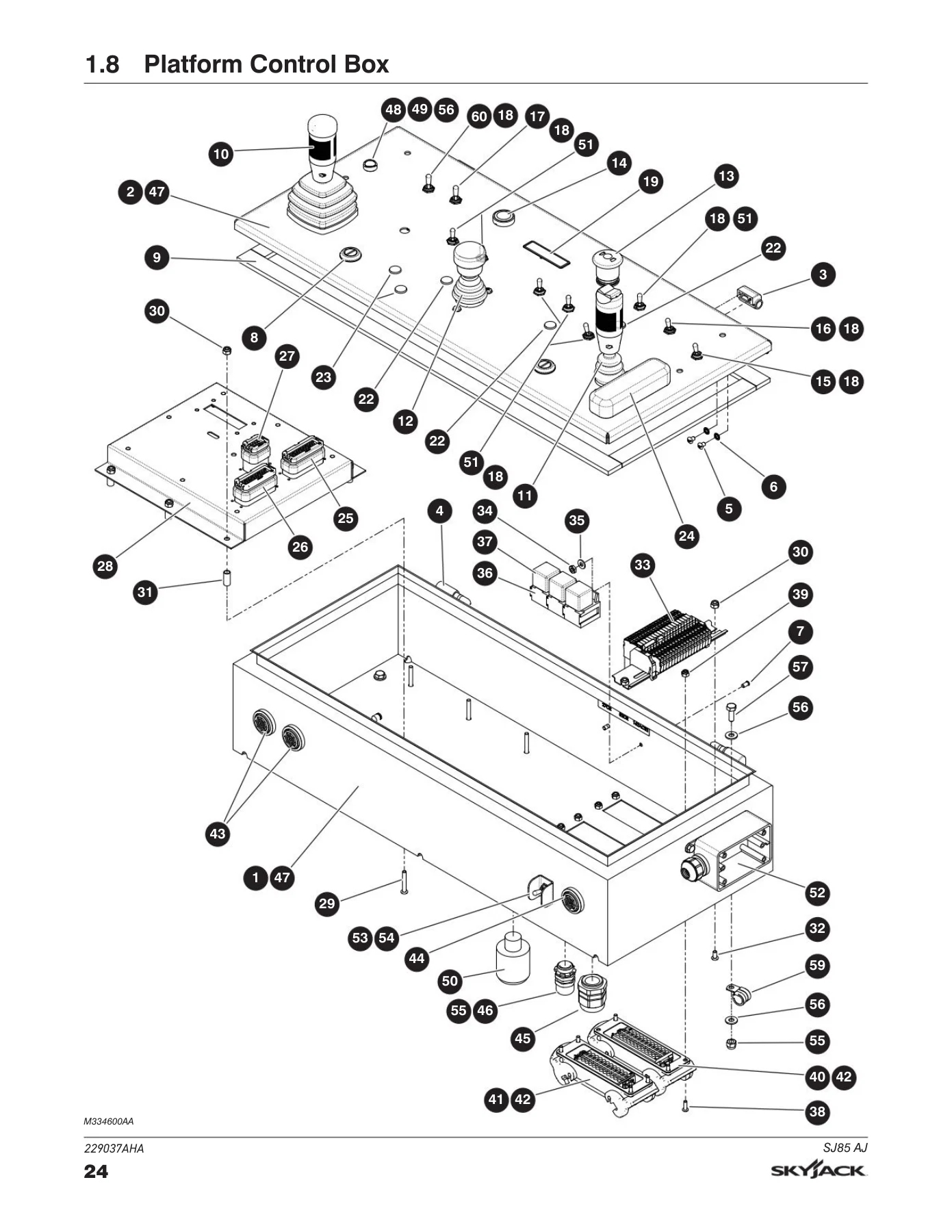
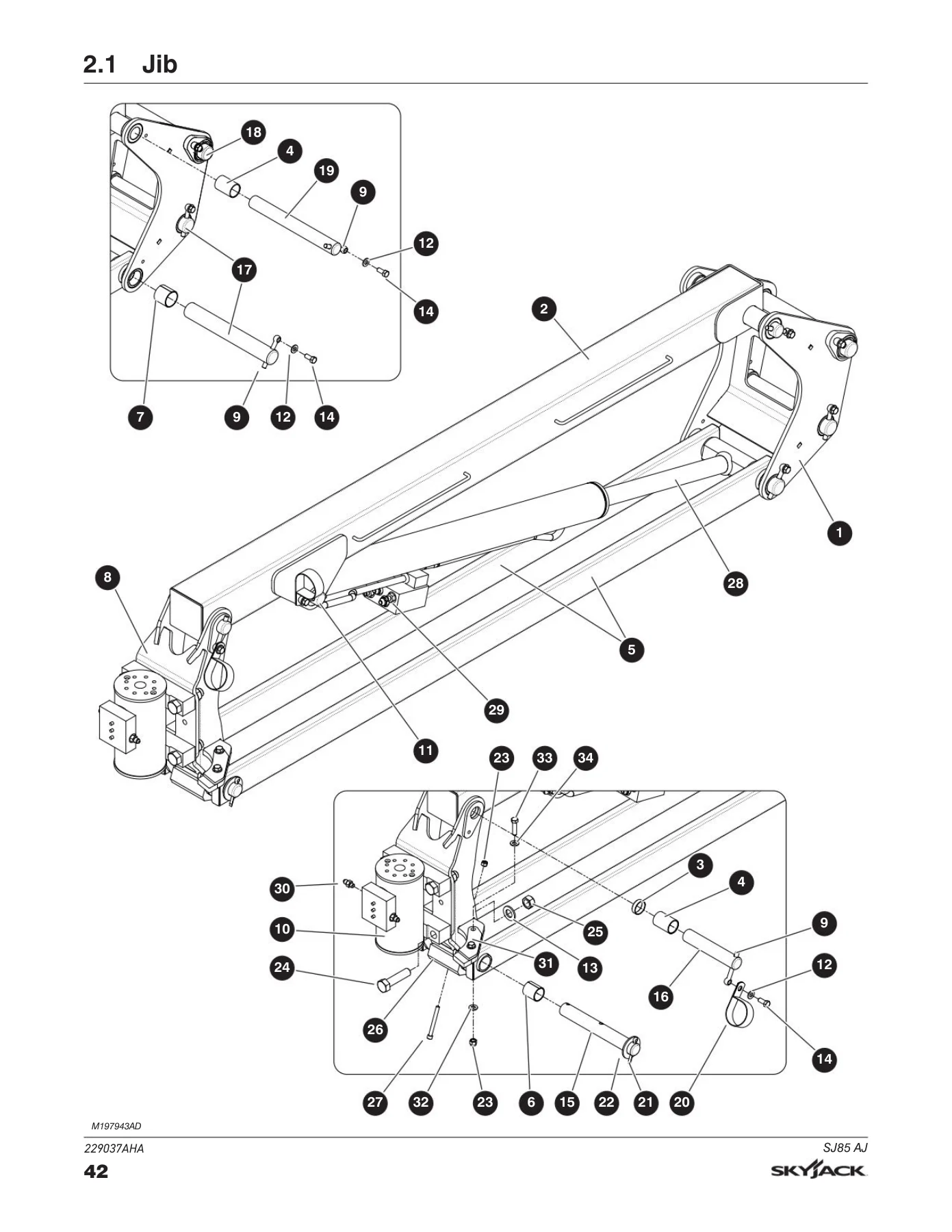
The catalog is divided into ten numbered sections, each built the same way: a labelled exploded illustration on one page and a numbered parts table on the following pages. The tables give the index number as it appears on the drawing, the Skyjack part number, the quantity required, and a description written noun-first so that like parts group together in the list. Where an assembly has more than one configuration, the variants are identified with a reference letter – A, B, C, D – at the head of the list, and each individual line carries the letter of the assembly it belongs to. Bullets in the description column show the parent-child structure, so it is immediately clear which items are subcomponents of a larger assembly and which are shared across every build.
This structure means the manual works as a disassembly guide as well as an ordering tool. The exploded views show the relative location of components in the order they come apart, which is exactly what a technician needs when a boom section, a swing drive or an axle hub has to be broken down and reassembled with fresh seals and wear pads.
Chapters Covered
- Section 1 – Platform
- Platform with three drop bars and platform with swing gate
- Platform base, railings, swing gate, drop bar gate
- Footswitch and platform control box
- Boom/turret controller, drive/steer controller, riser boom controller
- Platform terminal strip, SGE
- Platform outlet – ANSI/CSA; power to platform outlet and plugs – CE
- Section 2 – Boom
- Jib and jib manifold
- Cable track, fly boom, main boom
- Upper pivot, upper riser arm, 3rd riser arm
- Lower pivot, link arm, 2nd riser arm, lower riser arm
- Limit switches
- Section 3 – Cylinders
- Jib cylinder and slave cylinder
- Extension cylinder and master cylinder
- Main lift cylinder and riser cylinder
- Axle lock cylinder
- Section 4 – Turret
- Turret, engine tray
- Cowling – engine side and controls side
- Hydraulic tank, fuel tank – diesel, fuel tank – gasoline
- Swing drive
- Main and brake manifold hardware, main manifold, brake manifold
- Emergency pump, batteries, battery cables
- Base controls, base terminal strip – ANSI/CSA & AS, base terminal strip – CE
- Counterweight – turret
- Section 5 – Base
- Chassis and rotary manifold
- Front axle: axle assembly, differential, hub reduction, brakes, central housing, steering assembly, trunnion
- Rear axle: differential, hub reduction, central housing, brakes
- Driveshaft, gear box and motors, gear box
- Tires, counterweight – base, propane tanks
- Section 6 – Engines
- Deutz TD2.9L: engine, air intake, radiator
- Deutz TCD2.2: engine, radiators split by serial number, air intake
- Deutz D2011: engine, air intake
- Kubota WG3800: engine, air intake, radiator, exhaust
- Engine coupling – Deutz and Kubota
- Drive and system pumps, engine controls, terminal strip – engine controls
- Section 7 – Electrical Harnesses
- Main harness
- Jib and platform rotate harness
- Control cables
- Engine harnesses – Deutz TD2.9L, Deutz TCD2.2, Kubota WG3800
- Glow plug harness – Deutz TCD2.2
- Section 8 – Hose Connections
- Standard hose numbering system
- Hydraulic hoses – boom, turret, drive and system pumps, base
- Fuel lines – Deutz TD2.9L and TCD2.2, Deutz D2011, gasoline Kubota WG3800, propane Kubota WG3800
- Grease line
- Section 9 – Optional Equipment
- Oil cooler with no generator, oil cooler
- Generator and cooler assemblies – 3.5 kW, 7.5 kW, 12 kW, and the generators themselves
- Generator and oil cooler wiring, welder
- Pipe rack, external railing, control box cover, tool caddy
- Work lights, flashing light, all motion alarm, residual current device
- Diesel scrubber, positive air shut-off, hostile environment
- Cold start package, arctic package, load circuit, block heater
- Air line to platform, half-height platform mesh
- Elevate telematics and telematics subscriptions
- Section 10 – Labels
- Label kits
- Labels – controls side, engine side, platform
Read end to end, this Skyjack SJ85 AJ parts manual gives a technician a complete map of the machine. It identifies the wear items that get replaced on a routine basis, the seals and bearings buried inside the axles and cylinders, the hydraulic and electrical hardware that connects the major assemblies, and the fasteners that hold it all together – each with a part number that can be quoted directly to a parts counter.
How the Parts Lists Are Organized
The foreword sets out the conventions used throughout the catalog. Parts are listed in the order of the reference numbers shown on the illustration, and the descriptions follow the noun-first method – for example, PIN, Clevis – so that a search for a component type returns every instance of it. Assemblies at the top of a list may be identified with a reference letter, and the individual lines beneath them carry the same letter where a part is specific to that configuration; a line with no letter is used in every build. Quantities are stated for each part, and where a quantity is marked AR it varies with the options fitted, so the order quantity has to be judged against the machine as built.
The opening pages also explain how to place an order: quote the model and serial number from the serial number plate, list the quantity needed and the length where the item is supplied in bulk, and give the part number and description exactly as printed in the manual.
Recommended Service Parts
A recommended service parts schedule sits at the front of the book and lists the consumables and service items with year 1, year 2 and year 3 quantities alongside the Skyjack part number. It covers engine service items for the Kubota WG3800 – oil filter, fuel pre-filter, primary and secondary air cleaner elements, thermostat, radiator hoses, fan belt, fuel pump, starter, alternator, spark plug, propane regulator, lock-off valve, EPR regulator and mixer – plus an electrical group covering batteries, relays, relay sockets, toggle switches, contact blocks, limit switches for boom angle, boom extension, riser, boom down cut-out and direction sensing, valve coils, the drive/steer joystick handle kit and keys.
A hydraulic group follows with the high pressure and return filter elements, and seal kits for the extend, lift, riser, master, slave, jib, axle lockout and steer cylinders plus the rotary actuator. Wear pads and shims for the boom, cowling latches, axle seals and O-rings, gear box input and output shaft seals, and the platform manual box are listed in the same schedule. This section alone tells a workshop which parts to hold on the shelf for a machine in daily service.
Hose and Fitting Identification
Section 8 opens with the standard hose numbering system, which decodes the hose part number into its fitting arrangement, hose size, length in whole inches and length in fractions. A prefix chart maps the H01 to H71 range to the fittings on each end and the SAE hose specification the hose must meet, and a hose size chart converts the two-digit size code to the actual inside diameter. Where a hose is not included in a kit and has to be ordered separately, the manual says so on the line itself.
Engines, Serial Ranges and Options
Four engine packages are documented: the Deutz TD2.9L, the Deutz TCD2.2, the Deutz D2011 and the Kubota WG3800. On the TCD2.2 the radiator and air intake sections are split by machine serial number, so the correct drawing is used for the machine in front of you – the manual distinguishes the ranges at S/N A303 000 553 and above from S/N A303 000 552 and below, and separately at S/N A303 000 533 and above from S/N A303 000 532 and below. Getting this right avoids ordering a radiator or intake part that will not fit.
Section 9 is the optional equipment catalog and is unusually wide, covering oil coolers, three generator sizes with their mounting and wiring, a welder, pipe rack, external railing, control box cover, tool caddy, work lights, flashing light, all motion alarm, residual current device, diesel scrubber, positive air shut-off, hostile environment kit, cold start and arctic packages, load circuit, block heater, air line to platform, half-height platform mesh, and the Elevate telematics hardware and subscription options.
Order the Right Part the First Time
With this Skyjack SJ85 AJ parts manual on hand, a technician can identify a failed component from the exploded drawing, confirm the exact part number and quantity, and check whether the machine’s serial number or engine package changes which variant applies – before the order is placed. That turns a guessing game at the parts counter into a single, correct purchase, and it gives a workshop the diagrams it needs to strip and rebuild the boom, the turret, the axles and the hydraulic manifolds to the manufacturer’s own assembly order.
The file is delivered as an instant PDF download after payment. There is nothing to ship and nothing to wait for. It opens on any computer, tablet or phone, the pages can be zoomed and printed, and a printed copy of the section you are working on can go straight onto the workshop bench next to the machine.
Reviews
There are no reviews yet.