★ TRUSTED BY 321,897+ PROFESSIONALS WORLDWIDE
🏒
Trusted Business
Verified & Licensed
πŸ›‘οΈ
Virus Free Files
100% Safe Downloads
πŸ”’
Secure Payment
SSL Protected
⚑
Instant Delivery
Available Immediately
Sale!

Skyjack SJ9250 RT Rough Terrain Scissor Lift Service Manual 2024 – PDF Repair Guide

Original price was: $34.95.Current price is: $21.95.

Complete Skyjack SJ9250 RT service manual (doc 167323AGA, 2024). Covers scheduled maintenance, troubleshooting, hydraulic and electrical schematics, outrigger calibration, engine service, and full repair procedures. 180-page PDF.

⚑
Instant PDF Download
Available immediately
πŸ’Ύ
Save to Your Device
Download & keep forever
πŸ›‘οΈ
Antivirus Scanned
100% virus-free
🌍
Trusted Worldwide
175,000+ customers

Description

Skyjack SJ9250 RT Service Manual – 2024 Edition (167323AGA)

This is the complete service manual for the Skyjack SJ9250 RT rough terrain scissor lift, document number 167323AGA, dated 2024. It is the full workshop reference used to maintain, troubleshoot, and repair the SJ9250 RT across all covered serial number ranges, from scheduled inspections right through to component-level hydraulic and electrical repair. Every procedure, specification table, wiring schematic, and hydraulic diagram is included in a single 180-page PDF.

Whether you are a fleet maintenance technician, an independent repair shop, or an owner-operator keeping a SJ9250 RT in service, this Skyjack service manual gives you the factory procedures and the exact torque, pressure, and capacity figures needed to do the job correctly the first time.

File Details

  • Manual type: Service Manual
  • Brand: Skyjack
  • Model: SJ9250 RT
  • Document number: 167323AGA
  • Edition / date: 2024
  • Language: English
  • Page count: 180
  • File format: PDF

Chapters Covered

  • Section 1 – Scheduled Maintenance
    • Read and Heed, aerial platform and MEWP definitions
    • Purpose of equipment, use of equipment, manual, service policy and warranty
    • Operator safety reminders, warnings and precautions
    • Maintenance and inspection schedule
    • Owner’s annual inspection record
    • Replacement parts and maintenance safety tips
    • Hydraulic system and component maintenance and repair
    • Railing maintenance and repair
    • Scheduled maintenance inspections (manuals, labels, limit switches, electrical and control components, fuel compartment, engine compartment, platform assembly, lifting mechanism, base)
    • Function tests
  • Section 2 – Maintenance Tables and Diagrams
    • Specifications and features by serial number range
    • Maximum platform capacities (evenly distributed)
    • Tire specifications
    • Floor loading pressure (LCP and OUP)
    • Fluids: gear oil, hydraulic oil, engine oil, coolant, fuel
    • Torque specifications (cartridge, coils, SAE plugs, bolts)
    • Torque specifications for imperial and metric fasteners
    • Torque specifications for hydraulic couplings and hoses
  • Section 3 – System Component Identification and Schematics
    • Electrical symbol chart and hydraulic symbol chart
    • AC cord color code
    • Hydraulic component parts list and electrical component parts list
    • Platform control console wiring (ANSI/CSA)
    • Control cable assemblies diagram
    • Outrigger and hydraulic generator control console wiring
    • Base control console wiring (ANSI/CSA)
    • Hydraulic schematic and manifold component/port identification
    • Main manifold wiring diagram
    • Emergency lowering system wiring diagram
    • Powered extension platform wiring
    • Electrical panel diagrams (oil cooler, dual fuel, diesel, hydraulic generator options)
    • Auto-leveling outrigger wiring diagram
    • Horn, light, and beeper wiring diagram
    • Engine harness wiring (Kubota diesel and dual fuel)
    • Telematics harness wiring (Kubota diesel and dual fuel)
    • Flashing light relay harness
    • Electrical panel diagrams by serial number range
    • Positive air shutoff option panels and harness
    • Full electrical schematic diagrams by engine type and serial range (Kubota diesel, Kubota dual fuel, all options, no options, KC)
    • Engine electrical schematic (Kubota dual fuel)
    • Engine interface harnesses (Kubota dual fuel)
    • ECU wiring diagram (Kubota dual fuel)
    • Platform control box wiring

    IMAGES PREVIEW

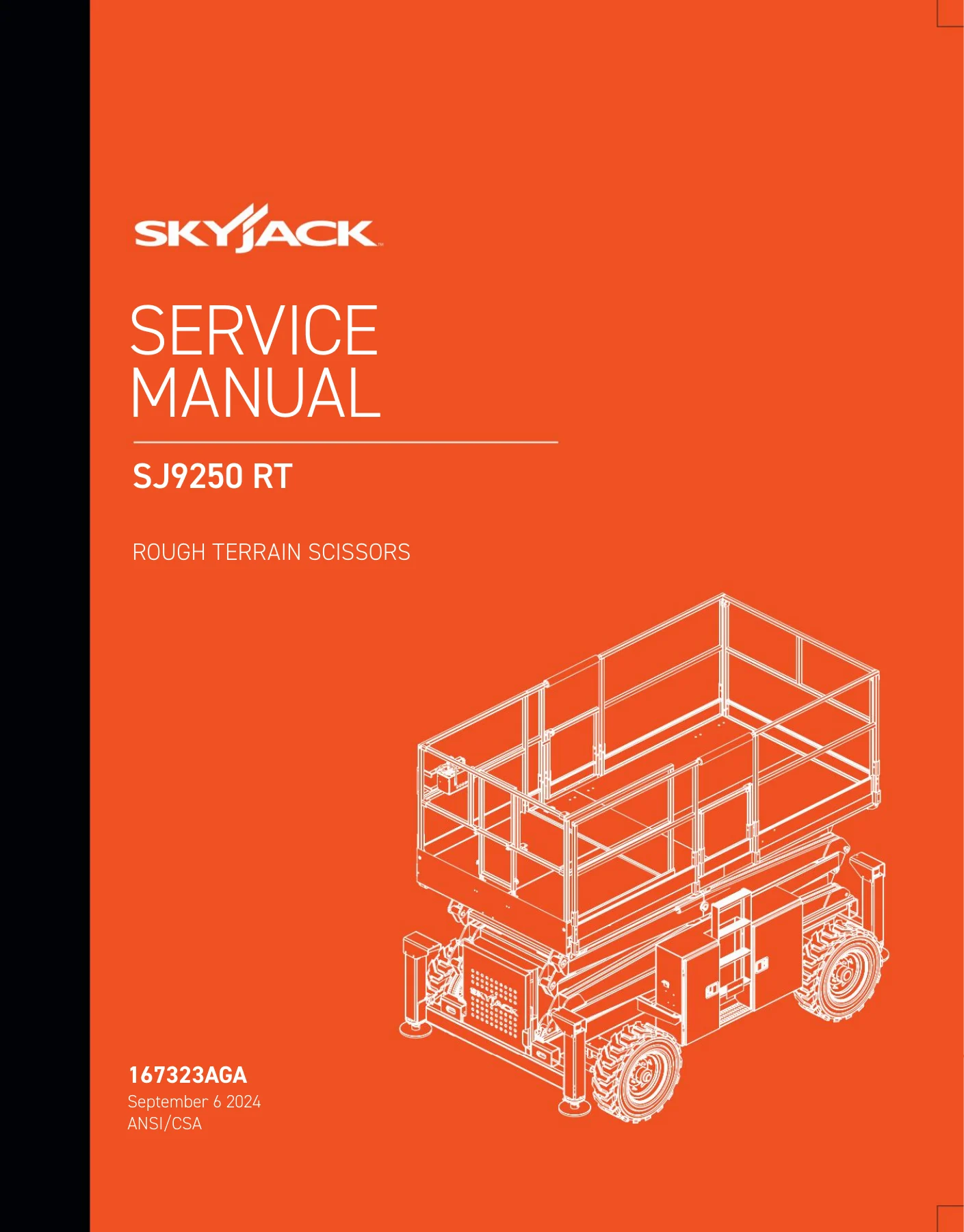
    Skyjack SJ9250 RT Rough Terrain Scissor Lift Service Manual 2024 - PDF Repair Guide β€” PDF page 1 preview
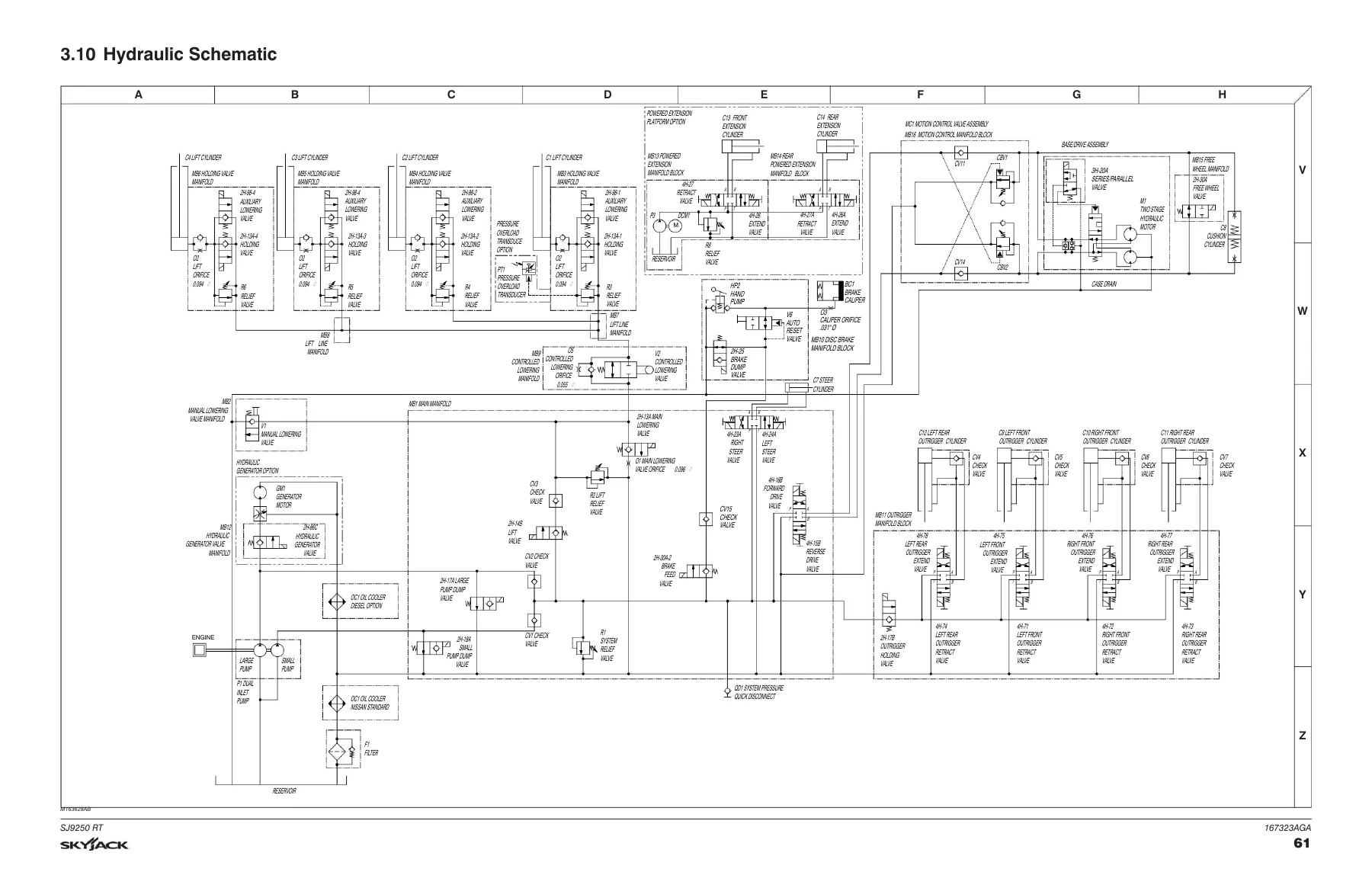
    Skyjack SJ9250 RT Rough Terrain Scissor Lift Service Manual 2024 - PDF Repair Guide β€” PDF page 61 preview
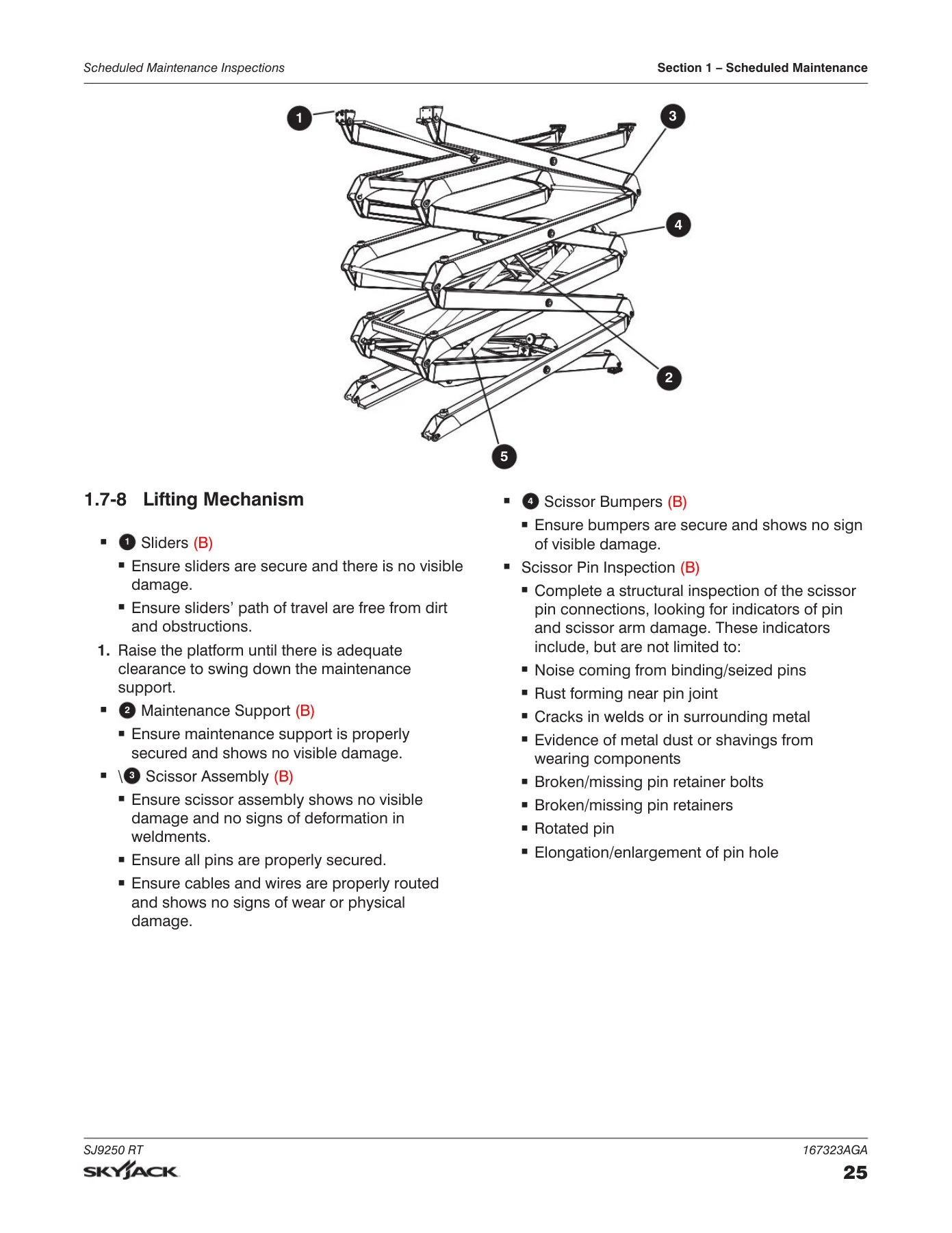
    Skyjack SJ9250 RT Rough Terrain Scissor Lift Service Manual 2024 - PDF Repair Guide β€” PDF page 25 preview

  • Section 4 – Troubleshooting Information
    • Electrical system troubleshooting: all controls inoperative, no power to platform, all functions inoperative from platform, engine crank and start faults, glow plug faults, throttle faults, drive and steer faults, brake release faults, speed range faults, up/down circuit faults, powered extension platform faults, hydraulic generator faults, outrigger faults (manual and auto-level), auto-level error codes
    • Hydraulic system troubleshooting: all functions, steering, drive speeds, drive direction, brake release, up and down circuits, powered extension platform, hydraulic generator, outrigger operation and drift
  • Section 5 – Procedures
    • Platform: gate spring hinge adjustment
    • Scissors: end of stroke limit switch (LS4) replacement and adjustment, high speed cutout (LS5) and lift cutout (LS1) replacement and adjustment
    • Engine: Kubota D1305 throttle setting, fuel filter element, fuel system bleeding, fan belt, air cleaner element, oil filter cartridge, oil change, coolant check and refill, radiator drain and refill, engine parameter display (KAntrak 1700), Kubota 972 and 2503 diagnostic trouble codes
    • Base: wheel bolt/nut torque, wheel installation and torque, grease points, platform control box reconnection for ground use, brake caliper adjustment, brake caliper bleeding, tilt switch setup and reprogramming, front axle hub procedure
    • Hydraulic: tightening and torque recommendations for couplings and hoses, holding valve check, system pressure setting, lift pressure setting, hydraulic oil change
    • Outriggers: mechanical limit switch wiring, upper limit switch (LS61-LS64) replacement and adjustment, lower limit switch (LS65-LS68) replacement and adjustment
    • EZcal diagnostic tool: key functions, controller flashing, outrigger codes
    • Auto-leveling outrigger PC board layout
    • GP-106 (OCM1) control module: instructions, auto-leveling setting and error codes, error code breakdown, controller setup, pin reference table
    • GP-108 control module: controller setup, pin reference table, LED error codes

In practice, this Skyjack SJ9250 RT service manual gives a technician the complete maintenance and repair path for the machine. The scheduled maintenance section tells you what to inspect and at what interval, the specification tables give you the exact capacities, fluids, and torque values, the schematics let you trace any circuit or hydraulic line, and the troubleshooting section walks through symptom-by-symptom diagnosis with probable causes and remedies. The procedures section then takes you step by step through the actual repair, from a limit switch swap to a full brake caliper bleed or a hydraulic pressure setting.

Complete PDF Bookmark Tree

Complete Bookmarks

The complete bookmarks in the β€œSkyjack SJ9250 RT Rough Terrain Scissor Lift Service Manual 2024 – PDF Repair Guide” are as follows:

Section 1 – Scheduled Maintenancep. 11
1.1 Read and Heedp. 11
1.1-1 Aerial Platform and Mobile Elevating Work Platform Definitionp. 11
1.1-2 Purpose of Equipmentp. 11
1.1-3 Use of Equipmentp. 11
1.1-4 Manualp. 11
1.1-5 Service Policy and Warrantyp. 11
1.1-6 Operator Safety Reminders, Warnings and Precautionsp. 11
1.2 Maintenance and Inspection Schedulep. 12
1.2-1 Owner’s Annual Inspection Recordp. 12
1.2-2 Replacement Partsp. 12
1.2-3 Maintenance and Service Safety Tipsp. 12
1.3 Hydraulic System & Component Maintenance and Repairp. 13
1.3-1 Maintenance Hintsp. 13
1.3-2 Maintenance Hintsp. 14
1.4 Railing Maintenance and Repairp. 14
1.5 About this Sectionp. 15
1.5-1 Service Bulletinsp. 15
1.5-2 Maintenance and Inspectionp. 15
1.5-3 Maintenance Instructionsp. 15
1.6 Owner’s Annual Inspection Recordp. 16
1.7 Scheduled Maintenance Inspectionsp. 18
1.7-1 Manuals (B)p. 18
1.7-2 Labels (B)p. 19
1.7-3 Limit Switches (B)p. 19
1.7-4 Electrical and Control Components and Hydraulic Compartmentp. 19
1.7-5 Fuel Compartmentp. 21
1.7-6 Engine Compartmentp. 22
1.7-7 Platform Assemblyp. 24
1.7-8 Lifting Mechanismp. 25
1.7-9 Basep. 28
1.8 Function Testsp. 30
Section 2 – Maintenance Tables and Diagramsp. 31
2.1 Specifications and Features 50 001 320 – 50 999 999 (Including 50 001 302 – 50 001 307)p. 32
2.2 Specifications and Features 50 001 153 – 50 001 320p. 33
2.3 Maximum Platform Capacities (Evenly Distributed)p. 34
2.4 Tire Specificationsp. 35
2.5 Floor Loading Pressurep. 37
2.6 Fluidsp. 38
2.7 Torque Specificationsp. 39
2.8 Torque Specifications for Fasteners (Imperial)p. 40
2.9 Torque Specifications for Fasteners (Metric)p. 41
2.10 Torque Specifications for Hydraulic Couplings and Hosesp. 42
Section 3 – System Component Identification and Schematicsp. 43
3.1 Electrical Symbol Chartp. 44
3.2 Hydraulic Symbol Chartp. 45
3.3 AC Cord Color Codep. 46
3.4 Hydraulic Component Parts Listp. 47
3.5 Electrical Component Parts Listp. 50
3.6 Platform Control Console Wiring – All Options (ANSI/CSA)p. 56
3.7 Control Cable Assemblies Diagramp. 57
3.8 Outrigger and Hydraulic Generator Control Console Wiringp. 58
3.9 Base Control Console Wiring (ANSI/CSA)p. 59
3.10 Hydraulic Schematicp. 61
3.11 HydraulicManifold Components and Port Identificationp. 62
3.12 Main Manifold Wiring Diagramp. 63
3.13 Emergency Lowering System Wiring Diagram (ANSI/CSA)p. 64
3.14 Electrical Wiring Diagram – Powered Extension Platformp. 65
3.15 Electrical Panel Diagram – Oil Cooler Option (ANSI/CSA)p. 66
3.16 Electrical Panel Diagram – Dual Fuel Engine with Hydraulic Generator Option (ANSI/CSA)p. 67
3.17 Electrical Panel Diagram – Diesel Engine with Hydraulic Generator Option (ANSI/CSA)p. 68
3.18 Auto-Leveling Outrigger Wiring Diagramp. 69
3.19 Horn, Light, and Beeper Wiring Diagramp. 70
3.20 Engine Harness Wiring Diagram – Kubota Diesel Enginep. 71
3.21 Engine Interface Harness Wiring Diagram – Kubota Dual Fuel Enginep. 72
3.22 Telematics Harness Wiring Diagram – Kubota Diesel Enginep. 73
3.23 Telematics Harness Wiring Diagram – Kubota Duel Fuel Enginep. 74
3.24 Flashing Light Relay Harnessp. 75
3.25 Electrical Panel Diagram – S/N 50 002 025. 50 002 025, 50 002 029 – 50 999 999p. 76
3.26 Electrical Panel Diagram – S/N 50 002 028, 50 002 027, 50 001 153 – 50 002 024p. 77
3.27 Electric Panel with Positive Air Shutoff Option – S/N 50 002 025, 50 002 026, 50 002 029 – 50 999 999p. 78
3.28 Electric Panel with Positive Air Shutoff Option – S/N 50 002 028, 50 002 027, 50 001 153 – 50 002 024p. 79
3.29 Positive Air Shutoff Harness Wiring Diagram – Diesel Enginep. 80
3.30 Electrical Schematic Diagram – Kubota Diesel Engine with All Option (ANSI/CSA) – S/N 50 002 025, 50 002 026, 50 002 029 – 50 999 999p. 81
3.31 Electrical Schematic Diagram – Kubota Diesel Engine with All Option (ANSI/CSA) – S/N 50 002 028, 50 002 027, 50 001 153 – 50 002 024p. 82
3.32 Electrical Schematic Diagram – Kubota Dual Fuel Engine with All Options (ANSI/CSA) – S/N 50 002 025, 50 002 026, 50 002 029 – 50 999 999p. 83
3.33 Electrical Schematic Diagram – Kubota Dual Fuel Engine with All Options (ANSI/CSA) – S/N 50 002 028, 50 002 027, 50 001 1533 – 50 002 024p. 84
3.34 Electrical Schematic Diagram – Kubota Dual Fuel Engine with No Options (ANSI/CSA) – S/N 50 002 025, 50 002 026, 50 002 029 – 50 999 999p. 85
3.35 Electrical Schematic Diagram – Kubota Dual Fuel Engine with No Options (ANSI/CSA) – S/N 50 002 028, 50 002 027, 50 001 153 – 50 002 024p. 86
3.36 Electrical Schematic Diagram – All Options (KC) – S/N 50 002 025, 50 002 026, 50 002 029 – 50 999 999p. 87
3.37 Electrical Schematic Diagram – All Options (KC) – S/N 50 002 028, 50 002 027, 50 001 153 – 50 002 024p. 88
3.38 Engine Electrical Schematic – Kubota Dual Fuel Enginep. 89
3.39 Engine Interface Harnesses – Kubota Dual Fuel Enginep. 90
3.40 ECU Wiring Diagram – Kubota Dual Fuel Enginep. 91
3.41 Platform Control Box Wiringp. 92
Section 4 – Troubleshooting Informationp. 93
4.1 Introductionp. 93
4.2 Electrical Systemp. 93
4.2-1 All Controls Inoperativep. 94
4.2-2 No Power to Platformp. 94
4.2-3 All Functions Inoperative from Platformp. 95
4.2-4 Engine Does Not Crank from Platformp. 95
4.2-5 Engine Does Not Crank from Base Controls (Kubota dual fuel)p. 96
4.2-6 Engine Does Not Crank from Base Controls (Kubota diesel)p. 97
4.2-7 Engine Cranks but Stops Cranking after a few secondsp. 97
4.2-8 Glow Plugs Inoperative from Engine Controlsp. 97
4.2-9 Glow Plugs Inoperative from Platform (Additional)p. 97
4.2-10 Engine Cranks but Does Not Start (Kubota diesel)p. 98
4.2-11 Engine Cranks but Does Not Start (Kubota dual fuelp. 98
4.2-12 Mid Throttle Inoperative (on demand) (Kubota Dual Fuel)p. 99
4.2-13 High Throttle Inoperativep. 99
4.2-14 Drive and Steer Inoperativep. 100
4.2-15 Brakes Do Not Releasep. 101
4.2-16 Steer Right Inoperativep. 101
4.2-17 Steer Left Inoperativep. 102
4.2-18 Reverse Drive Inoperativep. 103
4.2-19 Forward Drive Inoperativep. 103
4.2-20 First Drive Speed and Steering Inoperativep. 104
4.2-21 Second Drive Speed Inoperativep. 104
4.2-22 Third Drive Speed Inoperativep. 105
4.2-23 High/Low Range Inoperativep. 106
4.2-24 Up Circuit Inoperative from Platform or Basep. 107
4.2-25 Platform Does Not Lift from Platform or Base Controls with Outriggers Extendedp. 108
4.2-26 latform Does Not Lift from Platform or Base Controls with Outriggers Retracted (lift operates correctly with outriggers extended)p. 109
4.2-27 Up Circuit Inoperative from Basep. 110
4.2-28 Down Circuit Inoperative from Platform or Basep. 110
4.2-29 Down Circuit Inoperative from Basep. 111
4.2-30 Powered Extension Platform Inoperativep. 111
4.2-31 Powered Extension Platform Does Not Extendp. 112
4.2-32 Powered Extension Platform Does Not Retractp. 112
4.2-33 Hydraulic Generator Inoperativep. 112
4.2-34 Hydraulic Generator Does Not Shut Off from Generator Switchp. 113
4.2-35 All Outriggers Inoperative (Auto-level and manual)p. 113
4.2-36 All Outriggers Inoperative (Auto-level and manual from platform controls)p. 114
4.2-37 All Outriggers Inoperative (Base Controls)p. 114
4.2-38 All Outriggers Inoperative (Auto-level) A: Led Power Indicator Light at Outrigger Control Module (OCM1) Not on Constantp. 114
4.2-39 All Outriggers Inoperative (Auto Level) B: Led Power Indicator Light at Outrigger Control Module (OCM1) Flashingp. 115
4.2-40 Left Front Outrigger Inoperative Manuallyp. 116
4.2-41 Right Front Outrigger Inoperative Manuallyp. 116
4.2-42 Right Rear Outriggers Inoperative Manuallyp. 116
4.2-43 Left Rear Outriggers Inoperative Manuallyp. 117
4.2-44 Individual Outrigger Functions Inoperative (Auto-level)p. 117
4.2-45 Auto-level Inoperativep. 117
4.2-46 Auto All Up Inoperative (Retract)p. 118
4.3 Hydraulic Systemp. 119
4.3-1 All Functions Inoperativep. 119
4.3-2 Steering Inoperativep. 119
4.3-3 Steer and First Drive Speed Inoperativep. 119
4.3-4 Lift and Second Drive Speed Inoperativep. 119
4.3-5 Drive Inoperativep. 119
4.3-6 Reverse Drive Inoperativep. 120
4.3-7 Forward Drive Inoperativep. 120
4.3-8 Brakes Do Not Releasep. 120
4.3-9 Up Circuit Inoperativep. 120
4.3-10 Down Circuit Inoperativep. 121
4.3-11 Powered Extension Platform Inoperativep. 121
4.3-12 Hydraulic Generator Inoperativep. 121
4.3-13 All Outriggers Inoperativep. 121
4.3-14 Left Front Outrigger Inoperativep. 121
4.3-15 Right Front Outrigger Inoperativep. 122
4.3-16 Right Rear Outrigger Inoperativep. 122
4.3-17 Left Rear Outrigger Inoperativep. 122
4.3-18 Outriggers Drift Inp. 122
Section 5 – Proceduresp. 123
5.1 Generalp. 123
5.1-1 Safety and workmanshipp. 123
5.2 Platformp. 124
5.2-1 Adjust the gate spring hingep. 124
5.3 Scissorsp. 124
5.3-1 Replace and adjust the end of stroke limit switch (LS4)p. 124
5.3-2 Replace and adjust the high speed cutout (LS5) and lift cutout (LS1) limit switchp. 126
5.4 Enginep. 129
5.4-1 Kubota D1305 engine throttle settingp. 129
5.4-2 Replace the fuel filter elementp. 130
5.4-3 Bleed the fuel system of airp. 131
5.4-4 Replace and adjust the fan beltp. 131
5.4-5 Replace the air cleaner elementp. 132
5.4-6 Replace the oil filter cartridgep. 133
5.4-7 Change the oilp. 133
5.4-8 Check and replenish the radiator coolant levelp. 134
5.4-9 Drain and refill the radiatorp. 134
5.4-10 Engine parameter display (KAntrak 1700)p. 135
5.4-11 Kubota 972 and 2503 – DTCp. 136
5.5 Basep. 143
5.5-1 Inspect and torque the wheel bolts and nutsp. 143
5.5-2 Install and torque the wheelsp. 143
5.5-3 Grease pointsp. 144
5.5-4 Reconnecting the platform control box for use from the groundp. 145
5.5-5 Adjust the brake caliperp. 146
5.5-6 Bleed the brake caliperp. 148
5.5-7 Tilt switch setup procedurep. 150
5.5-8 Front axle hub procedurep. 153
5.6 Hydraulicp. 155
5.6-1 Tightening and torque recommendations for hydraulic couplings and hosesp. 155
5.6-2 Do a check of the holding valvep. 156
5.6-3 Set the system pressurep. 157
5.6-4 Set the lift pressurep. 158
5.6-5 Change the hydraulic oilp. 159
5.7 Outriggersp. 160
5.7-1 Outrigger mechanical limit switch wiring diagramp. 160
5.7-2 Replace and adjust the outrigger upper limit switch (LS61, LS62, LS63, LS64)p. 161
5.7-3 Replace and adjust the outrigger lower limit switch (LS65, LS66, LS67, LS68)p. 162
5.8 EZcal Diagnostic Toolp. 163
5.8-1 Hand held EZcal calibration and diagnostic tool key functionsp. 163
5.8-2 Flash the controllerp. 164
5.8-3 Outrigger codesp. 165
5.9 Auto-leveling outrigger PC board layoutp. 166
5.10 GP-106 (OCM1) Control Modulep. 167
5.10-1 Outrigger control module (GP-106/OCM1) instructionsp. 167
5.10-2 Auto-leveling outrigger setting and error codesp. 170
5.10-3 Auto-leveling outrigger error code breakdownp. 171
5.10-4 Set up the GP-106 outrigger controllerp. 172
5.10-5 GP-106 Outrigger controller pin reference tablep. 173
5.11 GP-108 Control Modulep. 174
5.11-1 Set up the GP-108 controllerp. 174
5.11-2 GP-108 Outrigger controller pin reference tablep. 176
5.11-3 GP-108 LED error codesp. 178

What This Manual Enables You to Do

With this PDF on hand, you can perform the full range of work the SJ9250 RT requires: annual and quarterly inspections, engine service on the Kubota diesel and dual fuel engines, hydraulic system diagnostics and pressure setting, electrical fault tracing across the main manifold, outrigger system, and platform control circuits, brake caliper adjustment and bleeding, limit switch replacement and calibration on the scissors and outriggers, tilt switch setup and reprogramming, and outrigger control module setup using the EZcal tool and GP-106/GP-108 controllers.

Having the correct procedures and specifications matters because the SJ9250 RT is a rough terrain machine with multiple interacting systems – hydraulic, electrical, engine, outrigger, and tilt sensing. A torque value taken from memory or a generic table, a limit switch set to the wrong height, or a hydraulic pressure set outside the serial-plate value can lead to poor machine performance, component damage, or unsafe operation. This manual removes that guesswork and gives you the values and procedures the machine was designed around.

Instant PDF Delivery

The manual is delivered as a downloadable PDF immediately after purchase. There is no shipping, no waiting for a physical book, and no restrictions on where you can use it – open it on a laptop, tablet, or phone in the shop, or print the pages you need for the job at hand. Keep it on the service truck, in the maintenance office, or on the machine’s own device and you always have the full Skyjack SJ9250 RT service reference within reach.

Reviews

There are no reviews yet.

Be the first to review “Skyjack SJ9250 RT Rough Terrain Scissor Lift Service Manual 2024 – PDF Repair Guide”

What Our Customers Say

β˜…β˜…β˜…β˜…β˜… Live reviews from customers
Loading customer reviews...
0
    0
    Your Cart
    Your cart is emptyReturn to Shop
    πŸ›’
    Recently Purchased
    πŸ•’ verified order