
Sullair LS-25 150-200HP Rotary Screw Compressor Operator Manual & Parts List PDF
Original price was: $29.95.$17.95Current price is: $17.95.
Complete Sullair LS-25 operator manual and parts list for 150-200 HP / 112-149 KW air-cooled and water-cooled compressors, standard and 24KT. Covers installation, operation, Supervisor controller setup, maintenance, troubleshooting, exploded parts views and wiring diagrams.
Description
File Details
- Manual type: Operator’s Manual and Parts List
- Brand: Sullair
- Model series: LS-25
- Coverage: 150-200 HP / 112-149 KW, air-cooled and water-cooled, standard and 24KT
- Document number: 02250127-757
- Language: English
- File format: PDF
- Page count: 120 pages
Chapters Covered
- Section 1 – Safety: General precautions, personal protective equipment, pressure release, fire and explosion, moving parts, hot surfaces and sharp edges, toxic and irritating substances, electrical shock, lifting, entrapment
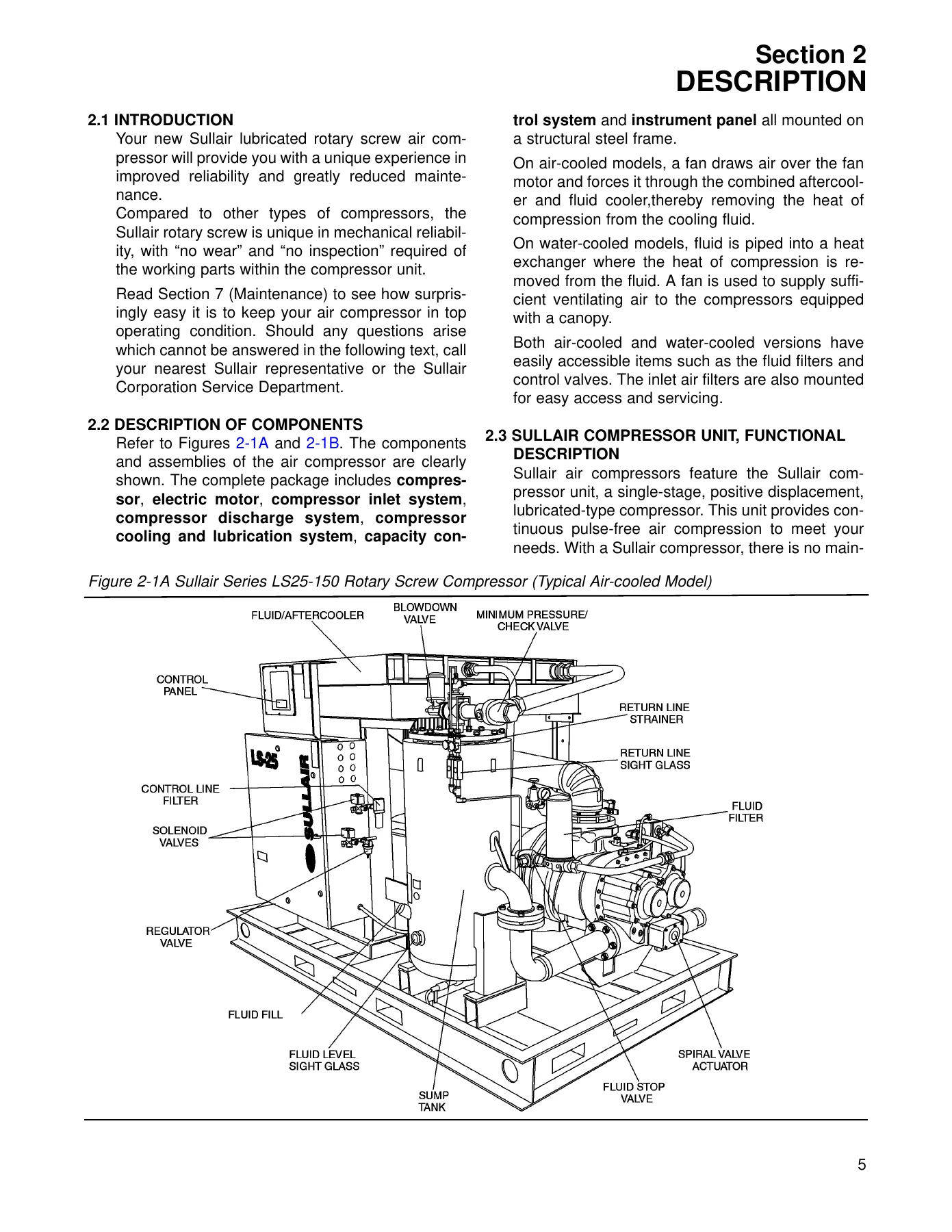
- Section 2 – Description: Description of components, Sullair compressor unit functional description, compressor cooling and lubrication system, compressor discharge system, control system, air inlet system, instrumentation, additional features
- Section 3 – Specifications: LS25-150 series specifications, lubrication guide for standard compressors, lubrication guide for 24KT compressors, application guide, lubrication change recommendations and maintenance
- Section 4 – Installation: Mounting of compressor, ventilation and cooling, service air piping, coupling alignment check, fluid level check, electrical preparation, motor rotation direction check
- Section 5 – Operation: General, purpose of controls (electro-mechanical), initial start-up procedure, subsequent start-up procedure, shutdown procedure
- Section 6 – Supervisor: Basic introduction, keypad, status displays, lamp indicators, parameter set-up, operating the compressor, purpose of controls, output relays, maintenance introduction, daily operation
- Section 7 – Maintenance: General, daily operation, maintenance after initial 50 hours, maintenance every 1000 hours, parts replacement and adjustment procedures, troubleshooting guides, calibration
- Section 8 – Illustrations and Parts List: Motor, compressor, frame and parts; air inlet system; cooling and lubrication (air-cooled and water-cooled); cooler assemblies; water piping; discharge system; Sullicon control; actuator valve; control system; unit tubing; instrument panel; electrical box; enclosure; decal group; wiring diagrams
This Sullair LS-25 150-200HP Rotary Screw Compressor Operator Manual & Parts List is the full document Sullair issued under number 02250127-757 for the LS-25 series rotary screw package. It is written for the 150 and 200 horsepower frames in both air-cooled and water-cooled builds, and it applies equally to compressors running standard Sullube fluid and to 24KT machines, with the differences called out where they matter. Rather than a thin operator leaflet, the book carries eight numbered sections that take the reader from safety rules through a full functional description of the compressor package, then into installation, start-up, everyday operation, maintenance intervals and fault finding, and finally into a complete illustrated parts breakdown with wiring diagrams.
How the Compressor Package Works, in Sullair’s Own Words
Section 2 is the technical heart of the manual. It explains the single-stage, positive displacement, lubricated rotary screw compressor unit and why the working parts are described as requiring no wear inspection. It then walks through the three functions of injected fluid – coolant, sealing of the leakage paths between the rotors and stator, and the lubricating film that lets one rotor drive the other – before following the air/fluid mixture into the combination receiver/sump where primary separation, fluid storage and final separator elements all live.
The cooling and lubrication chapter diagrams the path from the bottom of the receiver through the thermal valve and full-flow fluid filter and back to the compressor unit, with the thermal valve set to hold a minimum fluid temperature of 180 degrees F / 82 degrees C on standard machines and 195 degrees F / 91 degrees C on 24KT machines. The discharge system chapter covers the discharge check valve, the combination minimum pressure/check valve that holds at least 50 psig in the sump, the 200 psig pressure relief valve, the high pressure shutdown switch and the discharge temperature switch that trips at 240 degrees F / 115 degrees C. The control system chapter breaks compressor behaviour into four distinct phases – Start, Full Load, Modulation and Unload – and traces the spiral valve, inlet butterfly valve, pressure regulators, pilot valve and Sullicon Control through each one, including the AUTO mode that shuts a machine down after a set unloaded period and restarts it on demand.
Operation, Supervisor Controller and Maintenance
The operation section gives the purpose of every control and indicator on the electro-mechanical panel, then the initial start-up, subsequent start-up and shutdown procedures in numbered steps. For machines fitted with the Supervisor controller, a dedicated section documents the two-line display and keypad, the status messages (STOP, STANDBY, STARTING, OFF LOAD, ON LOAD, FULL LD, RMT STOP, SEQ STOP), the lamp indicators on the graphic panel, and the full parameter set-up sequence – unload pressure, load differential, P1 max, wye-delta transition timer, restart time, unload stop timer, language, units, communications ID, baud rate, sequence method, drain interval and drain time, lowest allowable pressure, recovery time, rotate time, machine capacity and sequence hours.
Maintenance is handled by hour interval: after the initial 50 hours (clean the return line strainers and orifices, change the fluid filter element) and every 1000 hours (clean the strainers, lubricate the Sullicon actuator linkage, change the fluid filter element). Individual procedures are written out for air filter element removal and inspection, fluid filter replacement, separator element replacement with the twelve hex head capscrews and torque sequence, control system pressure and differential adjustment, Sullicon actuator diaphragm replacement, and shaft coupling inspection, alignment and flexible element renewal for both the 150HP/112KW and 200HP/149KW drive arrangements, including the coupling gap, parallel offset and angular tolerance table.
Troubleshooting, Parts and Wiring Diagrams
Two separate troubleshooting guides are included – one for electro-mechanical controlled compressors and one for Supervisor machines. Each lists the symptom, the probable cause and the remedy across the faults a technician actually meets: compressor will not start, shuts down with air demand present, will not build full discharge pressure, line pressure rises above the cut-out setting, excessive fluid consumption, pressure relief valve opening repeatedly, motor overload messages, T1/T2 high temperature messages, P1/P2 high pressure messages, P3-LO oil pressure messages, separator maintenance messages and low water pressure messages. A calibration procedure follows for the pressure and temperature transducers.
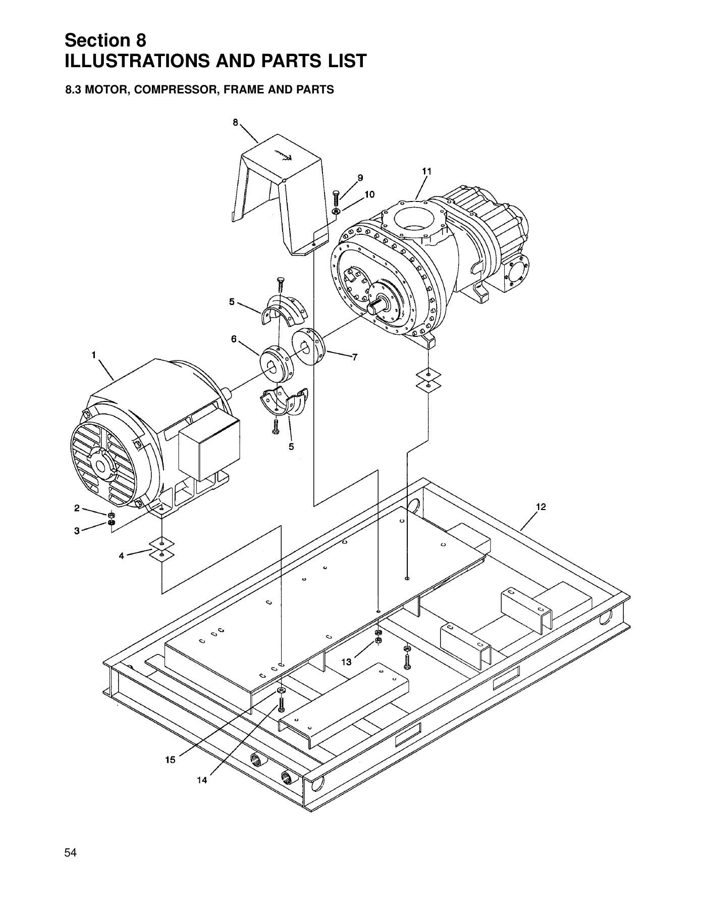
Section 8 is the parts half of the book and is where it earns its keep for anyone keeping an LS-25 running. It contains exploded illustrations and keyed parts tables for the motor, compressor, frame and coupling; the air inlet system including the 409264 filter and its primary and secondary replacement elements; the air-cooled and water-cooled cooling and lubrication circuits; the L model and XH model cooler assemblies; the water piping package; the air-cooled and water-cooled discharge systems; the Sullicon control; the actuator valve; the electro-mechanical and Supervisor control systems; unit tubing; both instrument panels; the electrical box; the enclosure; and a full decal group with air-cooled, water-cooled and typical enclosure location references.
Five wiring diagrams close out the manual: standard full voltage and wye delta for electro-mechanical controllers, standard full voltage and wye delta for Supervisor controllers, and a solid state starter diagram for Supervisor machines.
What This Manual Lets You Do
With this Sullair LS-25 manual in hand you can commission a new or relocated package correctly – level and grout the frame, size the ventilation, check the cooling water flow against the table, verify motor rotation and confirm coupling alignment before the first run. You can carry out the initial start-up sequence and set the pressure switch, differential and Sullicon control to the pressure range your plant actually needs. You can read the Supervisor displays and understand what each alarm and maintenance message is telling you before it becomes a shutdown. You can keep the fluid, filter and separator service on schedule, and when something does go wrong you can work from the symptom to the probable cause to the remedy instead of guessing. And because the parts sections are exploded and keyed, you can identify the exact component, gasket, orifice, valve or element you need and order it against the right number the first time.
Getting the procedures and pressures right on a rotary screw compressor matters. A spiral valve or Sullicon control that is out of adjustment will let line pressure climb above the cut-out setting, and a separator element left past its pressure drop limit costs you fluid and horsepower every hour it runs. The torque figures, gap tolerances, lubrication intervals and shutdown setpoints in this book are the ones the machine was built around.
IMAGES PREVIEW
This is a digital PDF download delivered instantly after payment. Nothing ships and there is nothing to wait for. Open it on a laptop in the shop, a tablet on the service truck or a phone at the compressor skid, print the pages you want to take to the machine, and keep the file for as long as you own the equipment.
Reviews
There are no reviews yet.