
Sumitomo 8FBR10-18 Electric Forklift Troubleshooting & Maintenance Manual PDF
Original price was: $39.95.$23.95Current price is: $23.95.
360-page Sumitomo troubleshooting and maintenance manual (5500518-00) for 8FBR10, 8FBR13, 8FBR14, 8FBR15 and 8FBR18 C900 electric reach trucks. Controller error codes, switch monitor, charger diagnostics, display panel, AC motor and full wiring schematics.
Description
Sumitomo 8FBR10-18 Forklift Troubleshooting & Maintenance Manual (5500518-00)
This Sumitomo 8FBR10-18 forklift troubleshooting and maintenance manual covers the C900 series 48 V AC electric reach trucks — models 8FBR10, 8FBR13, 8FBR14, 8FBR15 and 8FBR18 in S, C, A and W variants. It is the electrical, controller and charger diagnostic companion to the workshop manual: the document a technician opens when a truck throws an error code, when the display panel goes blank, or when travel, hydraulic or power steering operation stops for no obvious reason.
File Details
- Manual type: Troubleshooting / Maintenance Manual
- Document number: 5500518-00
- Brand: Sumitomo (Sumitomo Nacco Forklift Co., Ltd.)
- Models covered: 8FBR10, 8FBR13, 8FBR14, 8FBR15, 8FBR18 (S, C, A and W variants) — C900 series
- Language: English
- Page count: 360
- Format: PDF
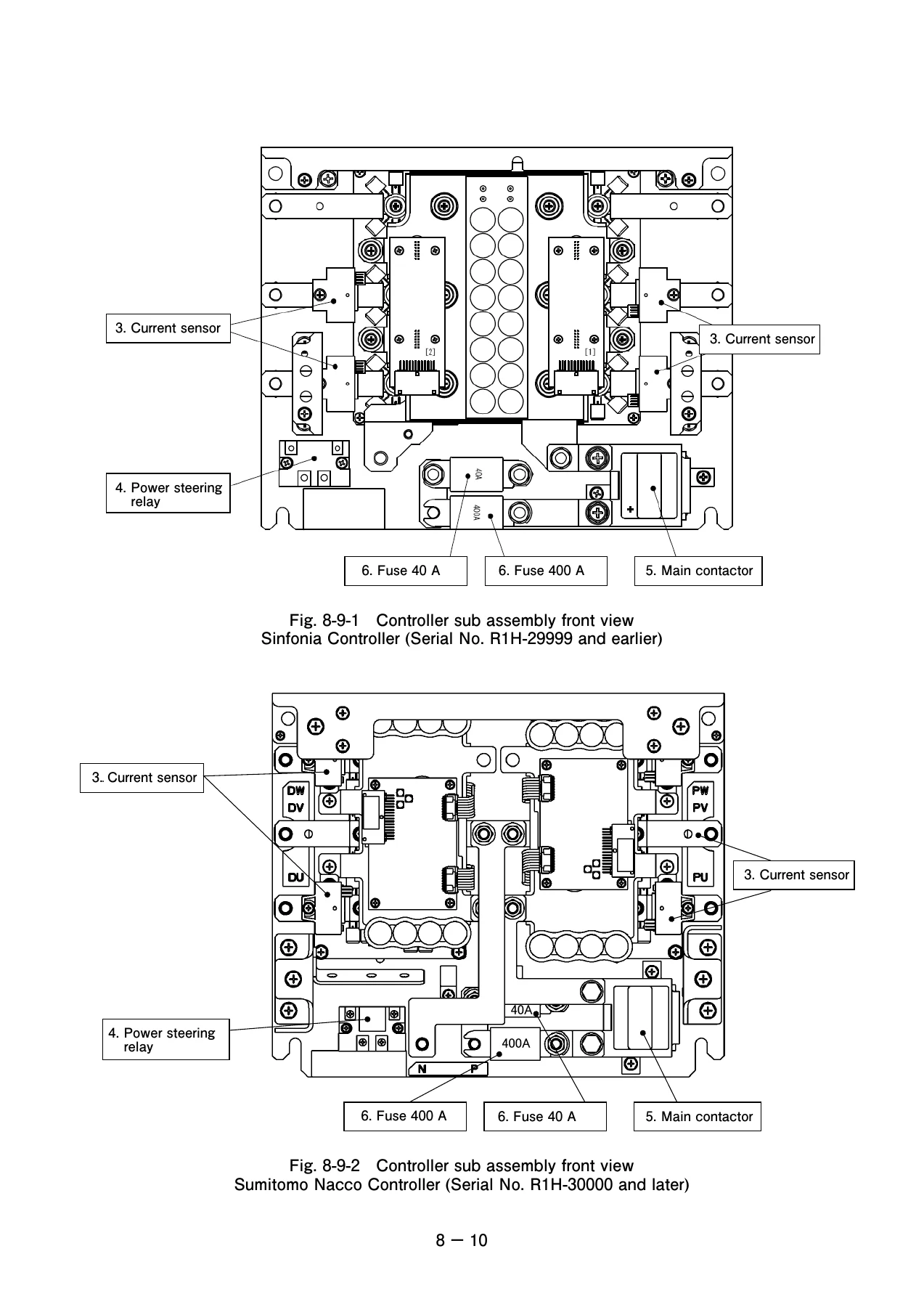
- Controller generations: Sinfonia (Serial No. R1H-29999 and earlier) and Sumitomo Nacco (Serial No. R1H-30000 and later)
Chapters Covered
- 1. Cautionary Notes on Inspecting and Repairing the Electrical System
- 2. Overview of Electrical System — control method, battery, motor, controller configuration, main parts, controller inputs, troubleshooting aids, and the changes introduced with the battery life mode
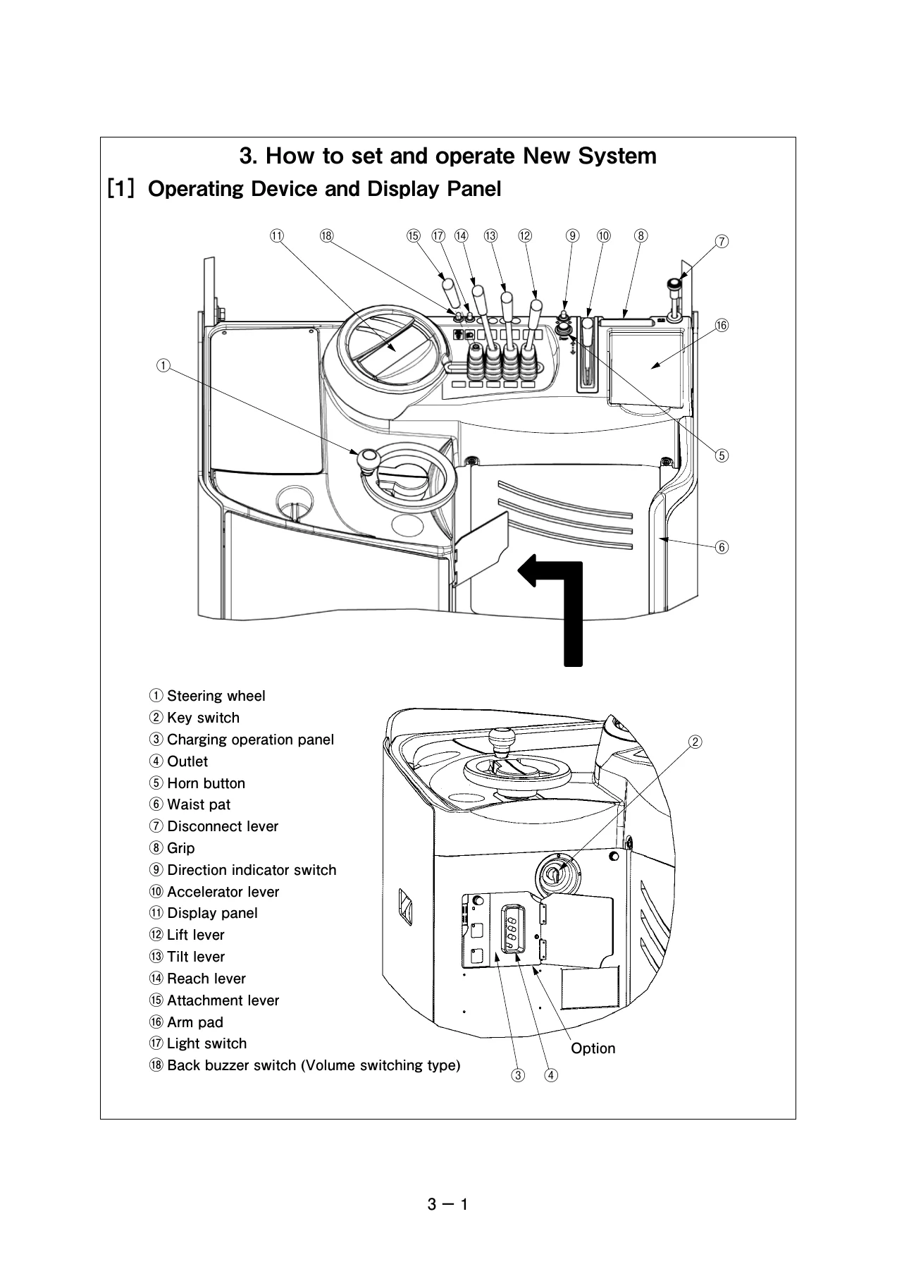
- 3. How to Set and Operate the New System — operating devices and display panel, key switch, accelerator, lift, tilt, reach and attachment levers, brake pedal, battery lock release pedal, switches, steering wheel, forks, safety laser, charging, battery pull-out and remounting
- 4. AC Motor — principles of operation, rotating field, comparison with the DC motor
- 5. Description of Controller Operation — travel system inverter, hydraulic system, power steering system, overall control system configuration, major functions of the travel, hydraulic and display systems
- 6. Controller Adjustment and Setup — controller installation and removal, CPU board, DIP switch settings, maintenance mode code numbers 400 / 450 / 500 / 550 / 700 / 750, option setting, password entry, display panel memory clear, software version confirmation
- 7. Display Panel — overview, specification, configuration, removal and installation, inspection, troubleshooting
- 8. Troubleshooting: Travel / Hydraulic / Power Steering / Display — controller troubleshooting, error code list, switch monitor, error log memory, failure-finding flow charts
- 9. Charger — specification, configuration and disassembly, operating instructions and function explanations, inspection, failure rectification and error list, charger troubleshooting
- 10. Schematic / Diagrams — electric components layout, controller components layout, schematic wiring diagram, main harness, built-in charger wiring diagram, stationary charger wiring diagram
Across its ten chapters the manual follows the truck from the battery terminals to the display panel. Chapter 2 sets out what the electrical system actually consists of on this platform — a 48 V battery with an SB175 plug, FET inverter control for both the travel and pump motors, an EPS power steering system driven by a DC motor and chopper, and a single integrated controller handling travel, hydraulic and steering duties. Chapter 5 then explains how that controller works in practice, including how the inverter converts the battery’s DC supply into three-phase AC for the travel and hydraulic motors, how the PWM switching sequence produces the output waveform, and how the power steering chopper circuit regulates assist torque from the torque sensor signal. Chapters 6 and 7 are the setup chapters: controller installation and removal, the CPU board DIP switch table, every maintenance mode adjustment code, and the display panel’s configuration and inspection points. Chapter 8 is the heart of the book for anyone chasing a fault, and Chapter 9 does the same job for the on-board and stationary chargers.
Error Codes, Switch Monitor and Error Logs
The troubleshooting chapter is organised around the way these trucks actually report problems. A full error code list breaks the codes into travel system (A-series), power steering (B-series), hydraulic (C-series), charge system (E-series), general (F-series) and display panel (G-series) groups, and for each code gives the error name, the detection condition, what the vehicle does when it is active, and the resetting method. The switch monitor section explains how to read live input and output signals from the controller on the display panel — accelerator sensor voltage, power steering torque sensor voltage, motor temperatures, forward/backward switch state, brake switch state, each load-handling lever switch, travel and hydraulic motor speed commands and currents, wheel angle sensor voltage, battery and AC voltage, and the charging counters. The error log memory section shows how to retrieve the five most recent error codes with their dates in reverse chronological order and how to map the logged bits back to specific faults.
Failure-Finding Flow Charts
Rather than stopping at a code list, the manual carries dedicated flow charts for the situations a technician actually meets. There are charts for a completely blank display panel, for a vehicle that shows normal data but will not travel, for a lever that fails to activate load handling on both standard and PCS specification trucks, for disabled steering, for an interlock mark that stays on screen, for an interlock that fails to engage, and for knocking or stalling when travel, hydraulics or steering are engaged. Each chart gives the measurement points, connector pin numbers and expected values, split where necessary between Sinfonia and Sumitomo Nacco controller generations, and each individual error code has its own diagnostic page covering the motor drive elements, speed sensors, temperature sensors, current sensors, contactor, fuses, boarding sensor, lock cylinder, interlock valve, wheel angle sensor, torque sensor and the display communication circuits.
Charger and Battery Diagnostics
Chapter 9 deals with the charging side in the same depth. It covers built-in and stationary charger specifications, the transformer assembly, rectifier, contactors and fuses, the quasi-constant voltage charging method and its characteristic curves, the automatic, manual equalizing, cold-area, reserved and auxiliary charging functions, power interruption behaviour and long-term storage handling. Inspection procedures for the contactor, fuses, rectifier, transformer, charging cord, power plug and charging outlet are included, along with transformer tap adjustment tables for both 50 Hz and 60 Hz supplies, and troubleshooting flow charts for no-charge, overcharge, undercharge and long charging time conditions.
Schematic and Wiring Diagrams
The final chapter provides the electric components layout, the controller components layout for both controller generations, the schematic wiring diagrams for standard and PCS specification vehicles, the main harness drawings for standard, option and PCS vehicles, and separate charger wiring diagrams for the built-in type and the stationary type — including the version with the optional automatic charger transformer tap switcher. Connector designations, wire colours and pin numbers are carried through the schematics so that the measurement points quoted in the troubleshooting chapter can be traced on the diagram.
What This Manual Lets You Do
With this manual on the bench you can read and interpret every error code these trucks produce, run the switch monitor to confirm whether a sensor, switch or lever is actually delivering the signal the controller expects, retrieve and clear stored error logs, set and adjust the maintenance mode code numbers that govern travel power, regenerative braking, travel and lift speed limits, suspension lock behaviour, load meter calibration, speed alarms and option outputs, configure password entry, clear display panel memory, confirm controller and display software versions, and work through the charger from the AC plug to the DC output. It also gives you the reference material to safely remove and refit the controller assembly and CPU board, apply thermal grease correctly, and discharge the inverter capacitor before touching motor or contactor terminals.
Why the Correct Reference Matters
These are inverter-driven AC trucks, and the failure modes are not the same as a DC machine. A speed sensor disconnection, a current sensor offset fault, a thermistor break or an accelerator signal outside its window will each produce a different code, a different vehicle response and a different repair path — and the two controller generations use different connector pin numbers for the same circuits. Working from the wrong chart, or assuming a Sinfonia pinout applies to a Sumitomo Nacco controller, sends you measuring the wrong terminal. The manual separates the two generations throughout, so the pin numbers, standard resistance values and switch monitor code ranges you are given match the truck in front of you.
IMAGES PREVIEW
Instant PDF Delivery
The Sumitomo 8FBR10-18 troubleshooting and maintenance manual is delivered as an instant PDF download — no shipping, no waiting for a parcel. Open it on a laptop, tablet or phone in the workshop, print the flow chart or schematic you need for the job, and keep the rest on file. Every page, diagram and table is available from the moment payment clears.
Reviews
There are no reviews yet.