
Tadano Faun ATF 130G-5 Carrier Control & Service System CSS Manual – Section B1
Original price was: $34.95.$19.95Current price is: $19.95.
Complete Section B1 service documentation for the Tadano Faun ATF 130G-5 carrier Control & Service System (CSS) – covering CMV cockpit menus, error codes, CAN bus architecture, outrigger controls, circuit diagrams, hydraulic schematics and emergency procedures across 197 pages.
Description
Tadano Faun ATF 130G-5 Carrier Control & Service System CSS – Section B1
This dedicated Section B1 document delivers the full Control & Service System (CSS) reference for the Tadano Faun ATF 130G-5 mobile crane carrier and superstructure. It is the companion volume a technician needs when working on the electronic monitoring, steering, suspension and outrigger systems – the systems that the crane’s own on-board diagnostics route through. Everything from the start-up screen logic and CMV menu structure through to CAN bus pin assignments, fuse charts and hydraulic piping diagrams is contained in a single 197-page PDF.
File Details
- Manual type: Carrier Control & Service System (CSS) service documentation – Section B1
- Brand: Tadano Faun
- Model: ATF 130G-5
- Language: English (with German annotations in circuit and hydraulic diagrams)
- Page count: 197 pages
- File format: PDF
- Document references: 99707707885, 99707701924, 99707701778, 99707701914, 99707784243, 99707797486, 99707025228
- Section: B1 – Carrier Control & Service System CSS
Chapters Covered
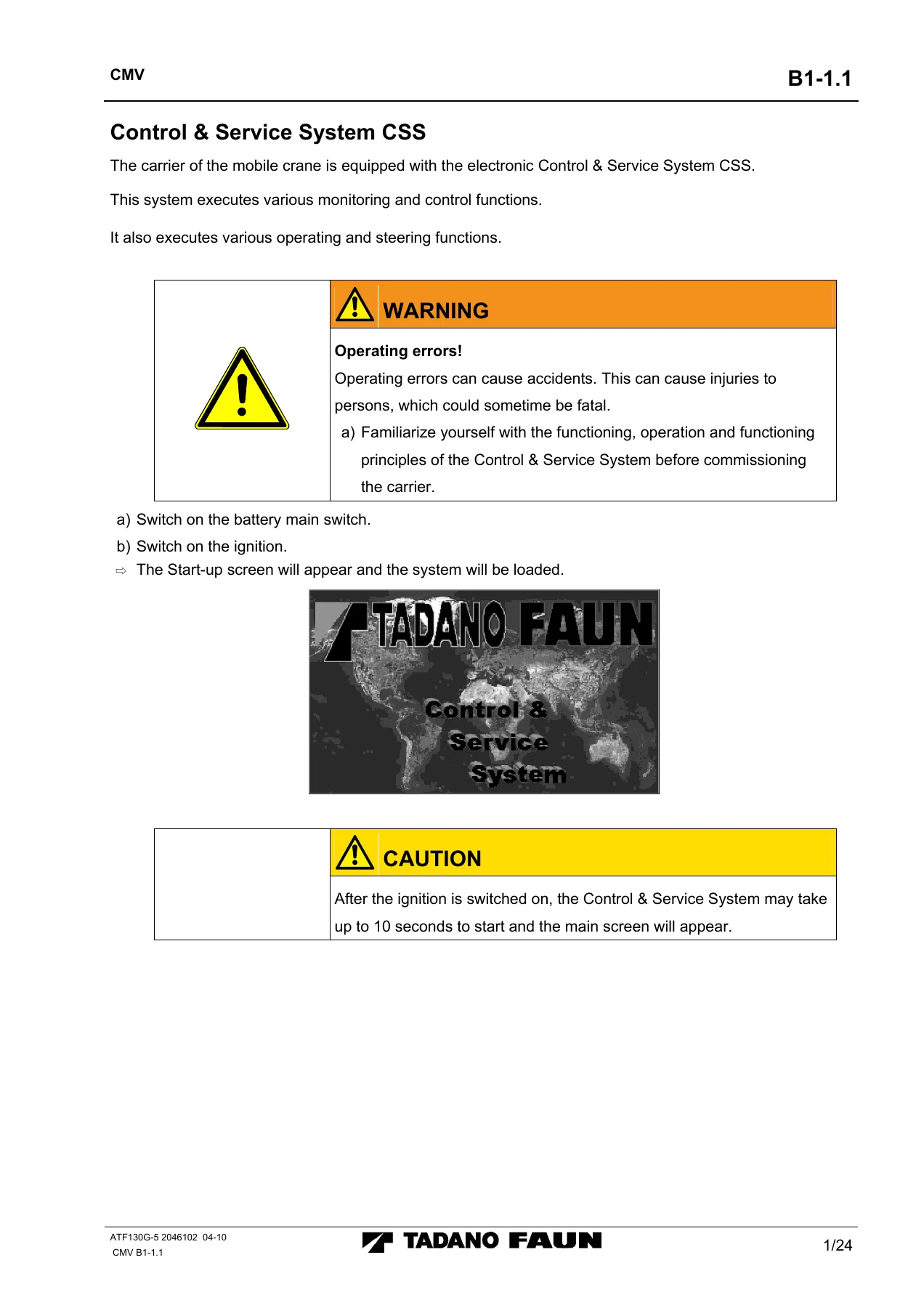
- Control & Service System CSS overview and start-up
- Warning, indicator and status symbols – positions 1-39 (brake pressure, oil level/temperature, coolant, ABS, steering pumps, CAN error, engine parameters, axle drive and differential locks, dolly mode, boom status, etc.)
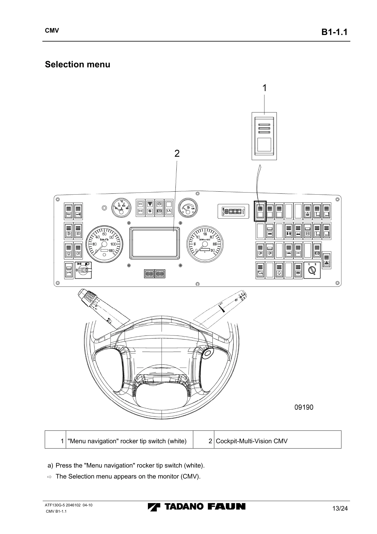
- Cockpit-Multi-Vision (CMV) monitor and menu navigation
- Drive information menu – 10×6 and 10×8 drive configurations, longitudinal and lateral differential locks
- Axle suspension locking information menu
- Steering information menu
- Brightness and contrast adjustment
- Circular spirit level information menu
- Engine management system information menu
- Service menu – CAN BUS STATE, CAN NODE STATE, error codes
- Rear area surveillance information menu
- Start-up screen and Main menu (leveling, lift/lower, outrigger pressure, contrast/brightness, extend/retract outrigger beams and cylinders, automatic leveling)
- Superstructure Control & Service System CSS with Cockpit-Graphic-Control (CGC)
- Main screen information displays and error messages – coolant temperature, on-board voltage, fuel gauge, level, supporting pressure, parking brake, hydraulic oil temperature and filter, engine oil level, air cleaner, CAN error, axle suspension locking
- Selection menu with operating elements – contrast/brightness, outrigger, engine control, carrier lighting
- Outrigger control screens – left, right, two/three outrigger and all-four outrigger
- Carrier engine control menu
- CAN BUS Service System – error code screens, FIFO screen, engine error code screen, suspension adjustment
- Checking inputs and outputs – options, all outputs, all inputs, D001-D008, set output, D016 Lib
- CAN design, DIP switches and fuses
- CAN BUS software specification – function descriptions for D001/D002, D003/D004, D005/D006, D007/D008, CGM outrigger casings and CGC superstructure functions
- CAN BUS pin assignments – D001, D002, D003, D004, D006, D007, D008, CMV P020, CGC superstructure, D700 transmitter
- Electronic rear axle steering – software download, parameter download, axle alignment procedure, reading and erasing error codes, diagnosis via WIN PCS, emergency control, PIN tables
- Components – installation place
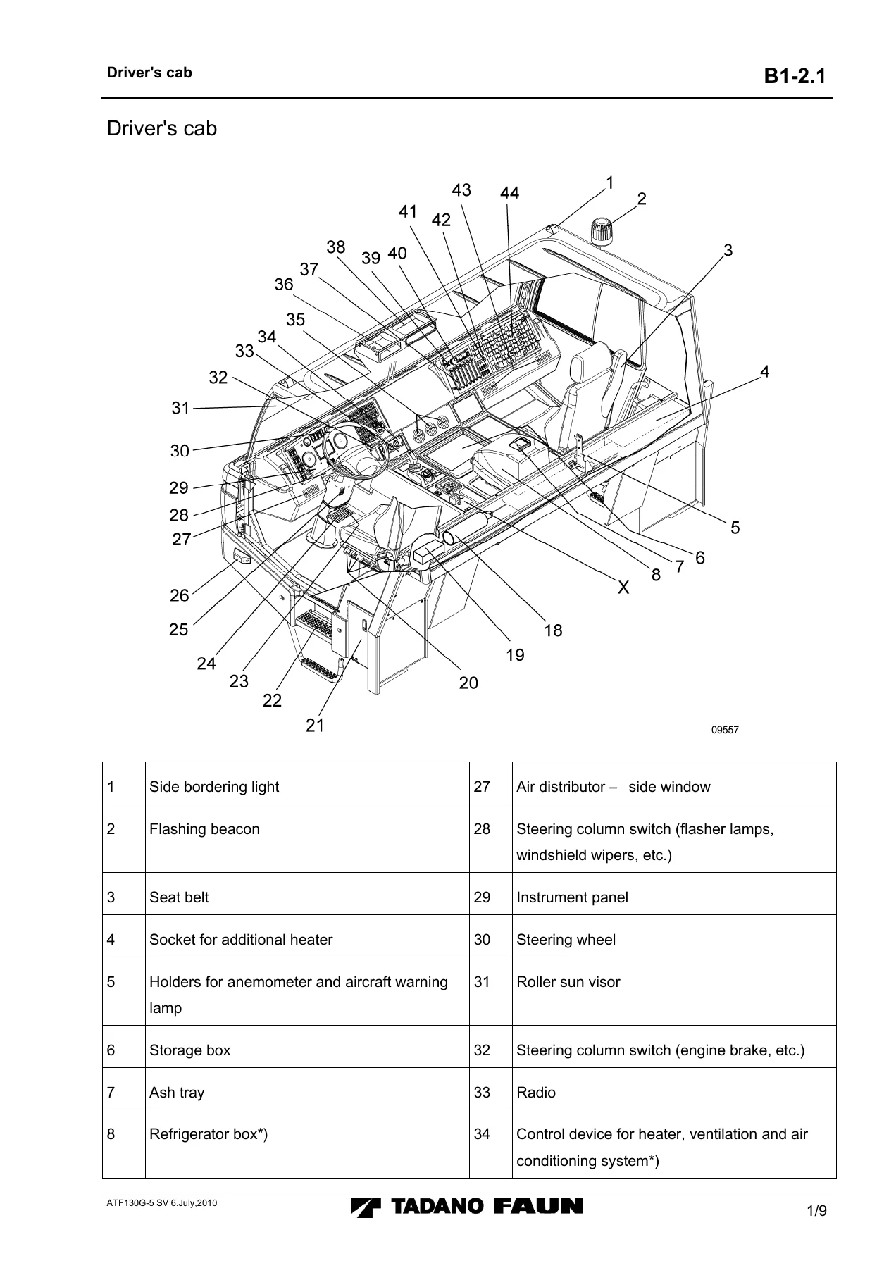
- Driver’s cab and operating elements layout
- Display, indicator and warning lamps
- Fuse and relay chart
- Circuit diagrams – carrier electrics, engine STOP, day running light, carrier heater
- Hydraulic piping diagrams – chassis, steering, emergency control
- Compressed air system of carrier
This is not a generic crane handbook. The Tadano Faun ATF 130G-5 CSS Section B1 is written around the specific electronic architecture of this 5-axle carrier – the DCP node network, the CMV colour display, the CGM outrigger control units, the CGC superstructure panel and the SLC steering computers. Every error code table, pin assignment and valve output reference belongs to this machine. That specificity is what makes it useful: when the CMV shows a flashing symbol, this document tells you which switch, sensor, valve, fuse or node to check – and gives you the DCP pin number, the sensor designation and the wiring diagram reference to find it.
What This Manual Enables You to Do
With the ATF 130G-5 CSS Section B1 on hand you can diagnose and repair the carrier and superstructure electronic systems directly rather than guessing at fault paths:
- Read and interpret every CMV and CGC warning symbol – brake circuit pressures, hydraulic oil condition, coolant level, ABS faults, CAN bus dropouts, axle suspension locking, leveling faults, boom status and more – with the recommended immediate action for each.
- Navigate the Service menus to pull CAN BUS and CAN NODE states, read error codes from D001 through D017 and the CGC (P810), and clear stored faults.
- Troubleshoot the CAN bus using the pin assignment tables, DIP switch settings, terminating resistor measurements (55-70 Ohms, 230-260 Ohms ring line) and the guidance on interchanging 55-pin DCP connectors to isolate a faulty control unit.
- Work on the outrigger system – manual and automatic leveling, extending/retracting beams and cylinders, holding axles, and the pressure/tilt values shown on the CGM screens.
- Perform axle alignment on the electronic rear axle steering using the menu-driven calibration procedure for axles 1, 2, 3, 4 and 5, and read/clear steering error codes on both SLC controllers.
- Diagnose via WIN PCS using the EA Data screen for digital, analog and PWM input/output monitoring when direct controller access is unavailable.
- Use the emergency control procedures for the rear axle steering when the electronic system fails – including connector X511/X512 repositioning and hydraulic override points for the 3rd, 4th and 5th axles.
- Trace electrical faults using the complete carrier circuit diagrams (99707707885 series), day running light diagram, engine STOP circuit and heater circuit – with fuse and relay charts to match.
- Trace hydraulic and pneumatic faults using the chassis steering hydraulic piping diagrams (99707701778), emergency control diagrams and the compressed air system schematic (99707784243).
- Verify power supply, ground and short-circuit conditions at DCP pins across every node, and check options configuration through the Service menu Options screens.
Correct procedures matter on a crane of this size. A mis-set axle suspension lock, an un-leveled chassis or a missed CAN fault can put the machine in an unstable condition. This document gives the technician the manufacturer’s own logic – the exact fault codes, the exact pin references, the exact valve outputs – so repairs are done to specification rather than by trial and error.
Delivery
IMAGES PREVIEW
The Tadano Faun ATF 130G-5 Carrier Control & Service System CSS – Section B1 is supplied as an instant-download PDF. No shipping, no waiting for a physical book. Open it on a laptop, tablet or phone in the workshop, print the pages you need for the job, and keep the full 197-page reference on file. Whether you are fault-finding a single warning lamp or rebuilding the CAN bus architecture from the ground up, the information is available the moment payment clears.
Reviews
There are no reviews yet.