
Tadano GR-750XL-2 Rough Terrain Crane Service Manual – Circuit Diagrams & Data (Serial 547121 & Up)
Original price was: $34.95.$19.95Current price is: $19.95.
Complete Tadano GR-750XL-2 rough terrain crane service manual covering hydraulic, pneumatic and electrical circuit diagrams plus full service data, adjustment pressures, assembly procedures and operation checks. Applicable to serial number 547121 and up, spec GR-750-2-00101 (2M2D North America).
Description
File Details
- Manual type: Service Manual (Circuit Diagrams and Data)
- Brand / Model: Tadano GR-750XL-2 Rough Terrain Crane
- Document number: GR-750XL-2-C1-U-2E
- Applicable spec. no.: GR-750-2-00101 (2M2D, North America)
- Applicable serial number: 547121 and up
- Language: English
- Page count: 137 pages
- File format: PDF
This Tadano GR-750XL-2 Rough Terrain Crane Service Manual is the companion volume to the operation and maintenance manual and the parts catalog. It carries the adjustment pressures, service data, assembly procedures, operation checks and complete system diagrams (hydraulic, torque converter, pneumatic and electrical) for the GR-750XL-2 under spec number GR-750-2-00101, 2M2D (North America). It applies to cranes from serial number 547121 onward. The document combines the Y-series of adjustment and check chapters with the Z-series of hydraulic, pneumatic and electrical system diagrams, making it the reference for anyone who needs to set pressures, trace a circuit, or confirm a specification on the machine.
Chapters Covered
- Y — Data, Adjustment and Checks
- Y-1 Service Data (oil and coolant amounts, operating speeds, hydraulic device specifications, swing section, boom section, wire rope, sheave, hook block, maintenance and replacement criteria, mass table)
- Y-2 Adjusting Pressure (Hydraulic Pressure) — winch, telescoping, elevating, steering, swing, outrigger, lower pilot pressure, remote control pilot pressure, flow control valve, torque converter oil pressure
- Y-3 Adjusting Pressure (Pneumatic Pressure) — pneumatic pressure setting table
- Y-4 Air Bleeding Procedure — hydraulic pump, winch brake, service brake, hydraulic motors, counterbalance valve, swing back-pressure valve, pilot circuit, positive control circuit, winch brake valve, jib lock pin and jib offset cylinder, suspension lock cylinder
- Y-5 Adjusting Procedure (Electric) — boom full retraction detection switches, jib stowed detection switch, jib lock pin retraction detection switch, drum rotation detection switches, over-front detection switch, control lever stand position detection switch, straight ahead detection switch, counterweight equipped detection switches
- Y-6 Assembly Adjustment (Crane Operation) — boom telescoping wire rope adjustment
- Y-7 Assembly Adjustment (Traveling Device) — service brake, accelerator, parking brake, tire and steering angle, engine speed, torque converter and transmission, braking force, headlight axes, hub nuts
- Y-8 Operation Check (Crane Operation) — outrigger status indicator, hoisting, backward stability control, outrigger emergency setting, jib, boom telescoping control modes I and II, warning, rope run-out detection, outrigger slide plate, eco mode
- Y-9 Operation Check (Traveling Device) — exhaust brake, automatic transmission, steering mode change, emergency switch, overshift prevention, warning, speedometer
- Y-10 Inspection and Maintenance
- Y-11 Boom Connecting Pin and Thread Size Table
- Z — System Diagrams
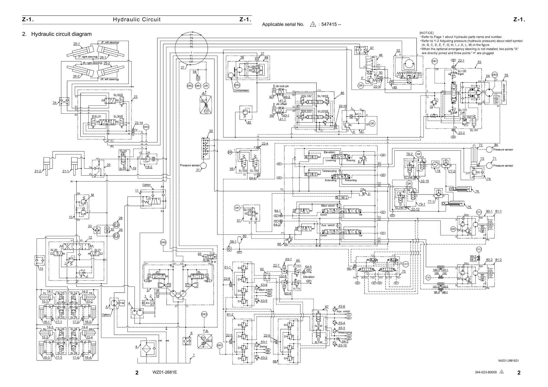
- Z-1 Hydraulic Circuit — hydraulic parts comparison table and full hydraulic circuit diagram
- Z-2 Torque Converter Circuit
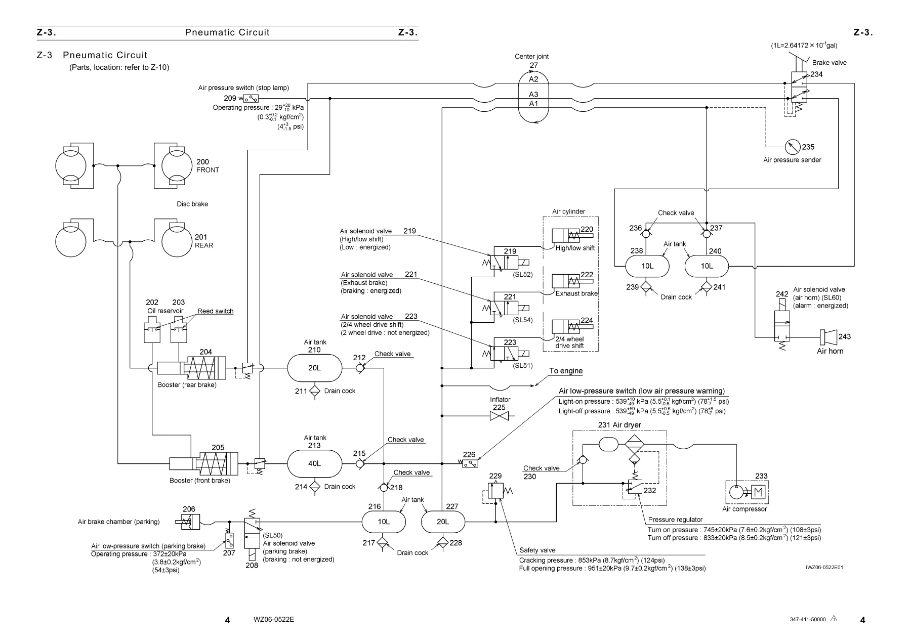
- Z-3 Pneumatic Circuit
- Z-4 Electric Circuit (Upper) (Crane) — crane main, swing table right and left, boom, AML, separated transport, AML override
- Z-5 Electric Circuit (Upper) (Carrier) — carrier main, T/M and O/R, accelerator, ICF, SCT
- Z-6 Electric Circuit (Lower) — lower main, lower air, engine without DPF
- Z-7 Hydraulic Parts Location Diagram (Upper)
- Z-8 Hydraulic Parts Location Diagram (Lower)
- Z-9 Hydraulic Parts Location Diagram (Torque Converter)
- Z-10 Pneumatic Parts Location Diagram
- Z-11 Electric Parts Location Diagram (Upper)
- Z-12 Electric Parts Location Diagram (AML, Overwinding)
- Z-13 Electric Parts Location Diagram (ICF, SCT)
- Z-14 Electric Parts Location Diagram (Lower)
- Z-15 Harness (Upper) (Crane)
- Z-16 Harness (Upper) (Carrier)
- Z-17 Harness (Lower)
Each section within the Y chapters is tied to a specific number: the pressure adjustment pages list the exact set pressures in MPa, kgf/cm² and psi, along with the engine speed and check procedure for each function; the electric adjustment pages give the switch dimension to adjust to and the tightening torque; the assembly adjustment pages cover brake pedal free play, steering angle, engine speed and torque converter oil level. On the Z side, the circuit diagrams are the full unfolded drawings — hydraulic circuit, torque converter circuit, pneumatic circuit, and the upper, carrier and lower electric circuits split across multiple sheets, plus the harness drawings with connector numbers, wire colour codes and routing. The Z-7 through Z-14 location diagrams show where every numbered hydraulic, pneumatic and electric component physically sits on the machine, so a diagram call-out can be traced to the actual part.
What This Manual Supports
The Tadano GR-750XL-2 service manual is built for the person who has to make the machine work correctly, not just read about it. The Y-2 hydraulic pressure chapter alone covers ten separate adjustment points: main and auxiliary winch hoist-up, boom extending and retracting, boom raising and lowering, steering, swing relief and overload relief, outrigger relief, lower pilot pressure, remote control pilot pressure, flow control valve, and torque converter oil pressure. Each one is given with the set pressure, the engine speed to hold, and the exact check procedure. The Y-5 chapter handles the electrical side: the boom full-retraction detection switches (3rd/top and 2nd), the jib stowed and jib lock pin retraction switches, main and auxiliary winch drum rotation detection switches, the over-front detection switch, the control lever stand position detection switch, the straight-ahead detection switch and the counterweight equipped detection switches — each with the dimension to adjust to and the tightening torque.
The air bleeding chapter (Y-4) is one of the more detailed sections, because the GR-750XL-2 has a long list of circuits that need to be bled in the right order: the hydraulic pump, the winch brakes (with the warning not to hoist up until bleeding is complete), the service brake boosters and wheel cylinders, the swing motor, winch motors and air conditioner motor, the winch counterbalance valve, the swing control back-pressure valve, the pilot circuit, the positive control circuit, the winch brake hydraulic valve, the jib lock pin and jib offset cylinder, and the suspension lock cylinder.
The assembly adjustment chapter (Y-6) walks through the boom telescoping wire rope adjustment step by step, with the order of nut-A, nut-B and nut-C tightening, the extension check of 1 to 5 mm between boom sections, and the follow-up check that the boom fully retracts. The Y-8 operation check chapter covers the telescoping mode I and mode II logic, the backward stability control at 76°, the outrigger emergency setting, the eco mode engine speed limits, and the rope run-out detection at three wraps.
On the diagram side, the Z-1 hydraulic circuit is the master drawing for the whole machine: steering, outrigger, suspension lock, winch, telescoping, elevating and swing circuits in one unfolded diagram with the numbered components keyed to the hydraulic parts comparison table. The Z-2 torque converter circuit covers the lock-up, PTO and clutch pressure circuits; the Z-3 pneumatic circuit covers the service brake, parking brake, air dryer, pressure regulator and the air solenoid valves for high/low shift, exhaust brake and 2/4-wheel drive shift. The electric circuits in Z-4 through Z-6 are split by area (crane upper, carrier upper, lower) and include the AML-C and MDT-9 connectors, the ICF and SCT terminals, and the accelerator and T/M circuits.
Why This Manual Matters
Setting a hydraulic pressure to the wrong value, bleeding a circuit in the wrong order, or adjusting a detection switch to the wrong dimension can turn a routine service job into a damaged pump, a brake that will not release, or a boom that will not fully retract. The Tadano GR-750XL-2 Rough Terrain Crane Service Manual gives the exact figures and the exact sequences that the crane was built to. The specification number GR-750-2-00101, 2M2D (North America) and the serial number range 547121 and up identify the machines this document applies to, so the buyer can confirm coverage before the work starts.
IMAGES PREVIEW
Instant PDF Delivery
The manual is delivered as a PDF download immediately after payment. There is no shipping and no waiting for a physical book. The file can be opened on a laptop, tablet or phone, and individual pages or sections can be printed for use in the workshop. Keep it on a device in the cab or the service truck and have the pressure table, the wiring diagram and the adjustment procedure on hand when the machine is in front of you.

Reviews
There are no reviews yet.