
TCM FD FG FHD FHG 20-35 Series Forklift Service Manual – 2.0 to 3.5 Ton Diesel & Gas Repair Guide PDF (SEF-2A0DE)
Original price was: $39.95.$26.95Current price is: $26.95.
171-page TCM service manual for FD, FG, FHD and FHG 20-35 series forklifts (2.0–3.5 ton). Covers K21, K25, C240, V2403 and QD32 engines, manual and automatic transmissions, drive axle, brakes, steering, hydraulics, load handling and full electric wiring. Document SEF-2A0DE, revised September 2012. Instant PDF download.
Description
This TCM Forklift Service Manual covers the FD, FG, FHD and FHG 20-35 series trucks in the 2.0 to 3.5 ton capacity range. Published by TCM Corporation under document number SEF-2A0DE, this 171-page service manual was written for technicians who service and repair these diesel and gasoline forklift trucks. It documents the major components and their service procedures, from the engine and both transmission types through the drive axle, brake system, steering system, hydraulic system, load handling system and electric wiring. The manual was first issued in February 2006 and last revised in September 2012, so the values and procedures reflect the later production trucks in this series.
File Details
- Manual type: Service Manual
- Brand: TCM
- Series: FD / FG / FHD / FHG 20-35
- Capacity range: 2.0 to 3.5 tons
- Language: English
- Page count: 171
- File format: PDF
- Document number: SEF-2A0DE
- Issued: February 2006
- Revised: May 2008, March 2009, September 2012
Chapters Covered
- 1. Engine
- 2. Manual Transmission System
- 3. Automatic Transmission System
- 4. Drive Axle
- 5. Brake System
- 6. Steering System
- 7. Hydraulic System
- 8. Load Handling System
- 9. Electric Wiring
1. Engine
The engine chapter opens with mounting details, bracket torque figures and rubber-mount service notes, then breaks into the fuel, cooling, accelerator and air intake systems. Gasoline coverage centres on the K21 and K25 four-cylinder, water-cooled engines, while diesel coverage spans the C240, V2403 and QD32 units. The fuel section walks through the 70-litre tank, the fuel level signal sender with its resistance table, and the fuel filter arrangement used on each engine family. Cooling covers the cross-flow radiator, reserve tank and the oil cooler built into the outlet tank on automatic transmission trucks. Valve clearance, compression pressure, injection timing, injection start pressure, fan belt deflection and gas cylinder mounting torque values are all tabulated for each engine.
2. Manual Transmission System
This chapter covers the synchromesh transmission in full, including the input gear, counter gear, main shaft and output gear layout, plus the sleeve-controlled shift mechanism. The synchronizer is broken down step by step — outer ring, middle ring, inner ring, insert and annular spring — with six stages of synchronisation illustrated. Forward and reverse power flows are traced through the gear train for both first and second speeds. Clutch cover, clutch disc, release cylinder, master cylinder, clutch pedal and the oil clutch variant are all treated with sectional views, and the clutch hydraulic circuit is shown end to end.
3. Automatic Transmission System
For automatic transmission trucks the manual details the torque converter, charging pump, transmission and transmission control valve. The torque converter section explains the pump wheel, turbine wheel, stator wheel and one-way clutch, and how reaction torque is converted to give the stall torque ratio. The transmission section covers the clutch pack assembly, its forward and reverse packs, and the internal oil passages. Transmission control valve coverage includes the inching valve, regulator valve, accumulator, shuttle valve and solenoid valve, with complete oil pressure circuit diagrams for neutral, forward gear, reverse gear and inching. Oil pressure check ports are identified on the case.
4. Drive Axle
Drive axle coverage begins with the housing, axle shaft, wheel hub, brake drum, oil seals and tapered roller bearings, using cutaway drawings for the 2.0–2.5 ton, 3.0 ton and 3.5 ton trucks. Bearing adjustment, hub starting force and grease fill volumes are specified. The reduction gear and differential chapter describes the split cross case, side gears, pinion gears, spider, thrust washers and ring gear, and gives the tightening torques for the drive pinion, ring gear, cross case and input flange. Wheel assembly and rim assembling bolt orientation are also covered.
5. Brake System
The brake chapter is a front two-wheel, internal-expansion hydraulic system with a duo-servo wheel brake. It covers the brake pedal and its adjustment, master cylinder construction (including the check valve that prevents vapour lock), the wheel cylinder and brake shoes, and the parking brake lever with its operating force setting. The automatic clearance adjuster is described for both truck groups — 2.0–2.5 ton trucks and 3.0–3.5 ton trucks — showing how reversing brake application turns the lever and moves the adjuster. A wheel brake troubleshooting table maps poor braking, noisy brake, uneven braking and soft or spongy brake symptoms to probable causes and remedies.
6. Steering System
Steering coverage starts with the centre-pin supported Elliot-type steering axle, the knuckle and king pin arrangement with its needle bearings and thrust bearing, and the wheel hub with tapered roller bearings. The steering wheel assembly, tilt lock lever and orbitrol follow, and the orbitrol section explains how the rotary control valve and metering device direct pressure oil to the power cylinder in neutral, counterclockwise and clockwise steering. Emergency manual steering when the pump fails is also described. The power cylinder is shown with its bushing, packing, rod packing and dust seal, and the steering wheel deviation control system — EPACS controller, compensation valve and tire angle sensor — is covered with the LED status table and centre position setting procedure.
7. Hydraulic System
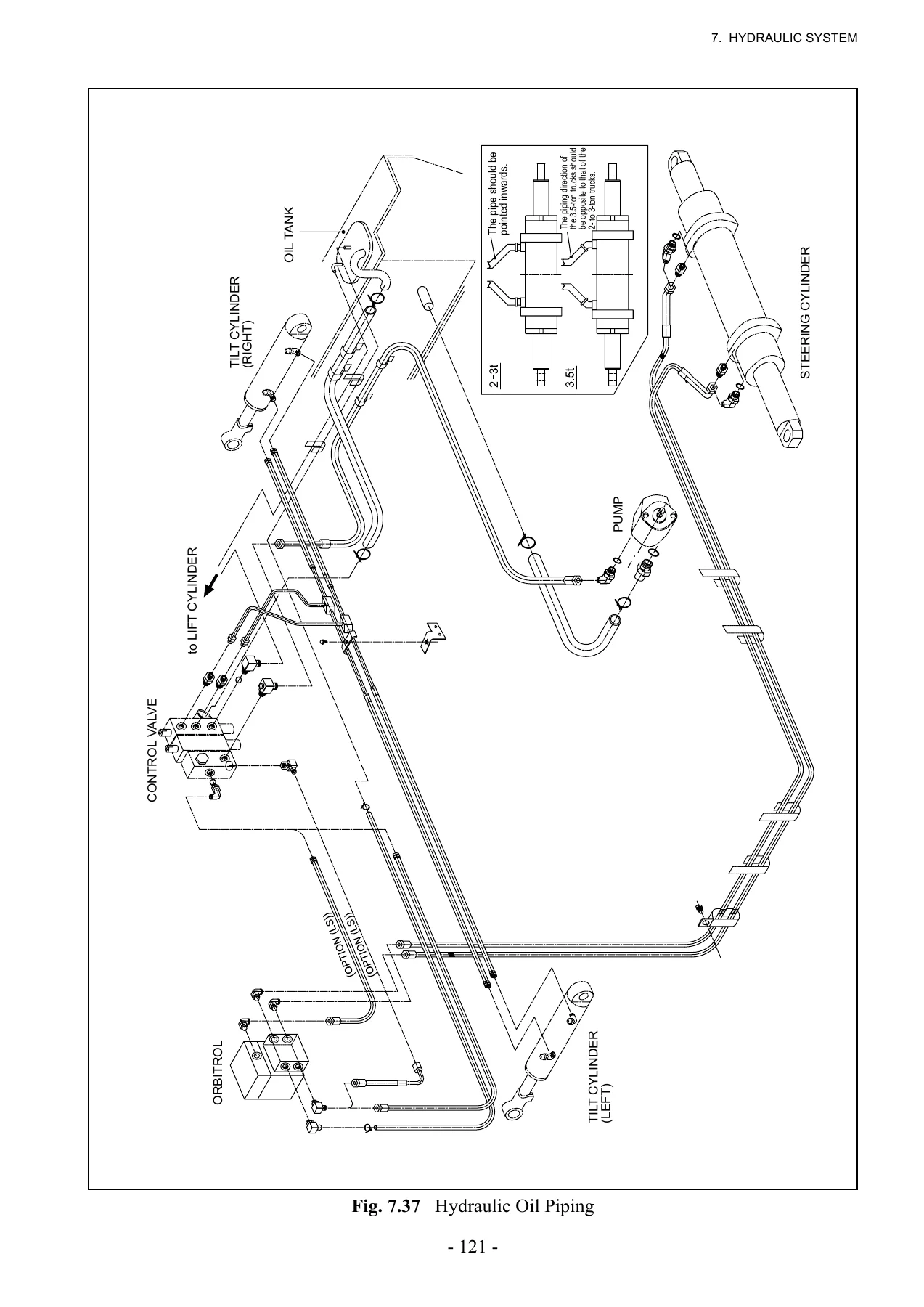
The hydraulic chapter covers the gear-type main pump and its pressure-balanced side plates, the front and rear control valve covers with main relief, flow priority and PF relief valves, and the lift and tilt sections. Lift section coverage includes the lock poppet, load check, solenoid valve and lift lock release screw, with circuit diagrams for neutral, lifting, lowering with solenoid off, and lowering with solenoid on. The tilt section explains the tilt lock mechanism and pilot spool operation. The lift cylinder is shown with its piston, wear ring, packing, cut-off valve and holder, and the flow regulator valve is described with a sectioned view. The tilt cylinder, oil tank, suction filter and return filter complete the chapter, and the hydraulic oil piping is drawn as a full system schematic.
8. Load Handling System
Load handling covers the roller-type two-stage telescopic mast with free lift, the outer and inner channels, the carriage with its end rollers, side rollers, shims, slippers and load backrest, and the roller positions for both 2 to 3 ton and 3.5 ton trucks. Chain and sheave arrangements on the lift cylinder are shown with adjustment nuts, lock nuts and cotter pins.
9. Electric Wiring
The wiring chapter opens with wire colour and connector symbols, then covers the 12 V battery and its location, the starter switch in OFF, ON and START positions, the starter circuit and battery charge circuit, the fuse box with its fuse ratings and spare fuse positions, and the lighting equipment — headlights, front and rear combination lights, work lights and license plate light. Combination switch unit functions are described, as are bulb replacement procedures. Full wiring diagrams are provided separately for the K21/K25 gasoline engine, V2403 diesel, C240 diesel and QD32 diesel truck variants.
Why This TCM Forklift Service Manual Matters
A 2.0 to 3.5 ton TCM forklift is a working machine, and the difference between a repair that lasts and one that comes back is usually the specification sheet behind it. This manual gives you the actual figures the TCM engineers published: valve clearances for K21, K25, C240, V2403 and QD32 engines, compression pressures, injection timing, hub starting force, clutch pedal play, brake shoe clearance, control valve relief pressures and lift cylinder natural oil limits. Every figure is specific to these trucks, so you are not guessing at torque values or clearances from a generic source.
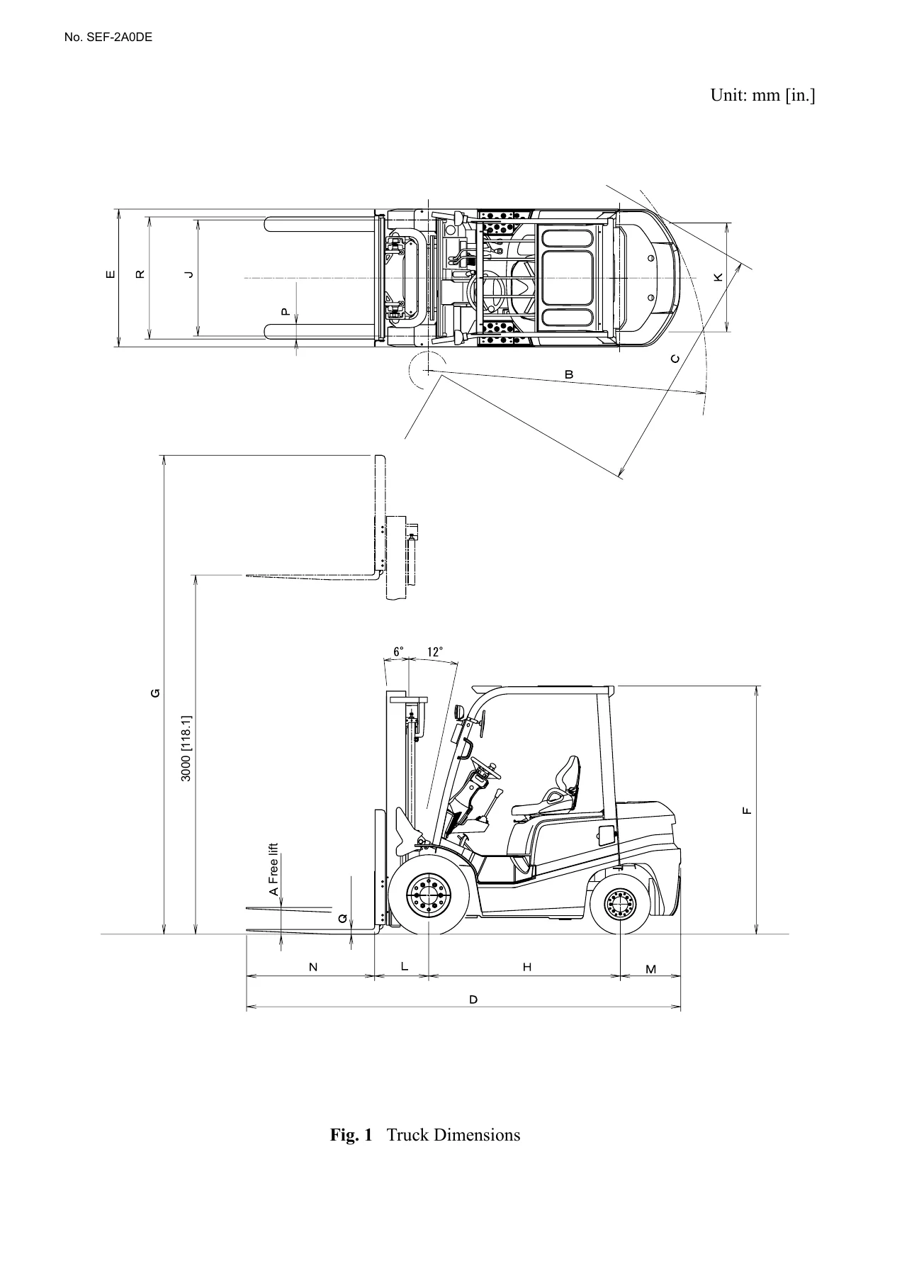
Because the manual covers both manual and automatic transmission trucks, both gasoline and three diesel engine families, and both the 2.0–2.5 ton and 3.0–3.5 ton brake and axle variants, one download covers a whole fleet of FD, FG, FHD and FHG trucks. The chapter-by-chapter structure with sectional views, exploded diagrams, hydraulic schematics and full wiring diagrams makes it usable both as a step-by-step repair guide and as a reference document when you need to confirm a procedure before starting a job.
The PDF is delivered instantly after payment, with no shipping and no waiting for a disc. It opens on any computer, tablet or smartphone, and every page — including the specification tables and the large fold-out-style wiring diagrams — can be printed or zoomed as needed. Keep a copy in the workshop, keep one on the service laptop, and you always have the TCM factory procedures for these forklifts within reach.
IMAGES PREVIEW
Reviews
There are no reviews yet.