
Toro Groundsmaster 4000-D Service Manual 02097SL Rev G – Model 30410 PDF
Original price was: $34.95.$19.95Current price is: $19.95.
Complete Toro Groundsmaster 4000-D (Model 30410) Service Manual – Publication 02097SL Rev G. Covers the Kubota V2003-T diesel engine, hydraulics, electrical system, axles, cutting units, and full electrical diagrams in 254 pages.
Description
Toro Groundsmaster 4000-D Service Manual – Model 30410
This is the full Toro Groundsmaster 4000-D Service Manual, publication number 02097SL, Revision G, dated 03/2018. It is the technician-level repair and diagnostic guide for the Groundsmaster 4000-D (Model 30410) commercial rotary mower, covering every major system on the machine in dedicated chapters. The Toro Groundsmaster 4000-D service manual walks through engine service, complete hydraulic system testing and repair, electrical troubleshooting and component testing, axles and planetaries, brakes, chassis, and the cutting units themselves – backed by schematics, flow diagrams, exploded views, and torque specifications throughout.
File Details
- Manual type: Service Manual (technician-level troubleshooting, testing, and repair)
- Brand: Toro
- Model: Groundsmaster 4000-D (Model 30410)
- Publication number: 02097SL
- Revision: Rev G
- Revision date: 03/2018
- Language: English
- Page count: 254 pages
- File format: PDF
Chapters Covered
- Chapter 1 – Safety: Jacking Instructions, Safety and Instruction Decals
- Chapter 2 – Product Records and Maintenance: Product Records, Maintenance, Equivalents and Conversions, Torque Specifications
- Chapter 3 – Kubota Diesel Engine: General Information, Specifications, Adjustments, Service and Repairs, Engine Removal, Engine Installation, Coupling Disassembly and Assembly
- Chapter 4 – Hydraulic System: Specifications, General Information, Hydraulic Schematic, Hydraulic Flow Diagrams, Special Tools, Troubleshooting, Testing, Adjustments, Service and Repairs
- Chapter 5 – Electrical System: Electrical Schematic, Circuit Diagrams, Wire Harness Drawings, Special Tools, Troubleshooting, Electrical System Quick Checks, Component Testing, Service and Repairs
- Chapter 6 – Axles, Planetaries, and Brakes: Specifications, Adjustments, Service and Repairs
- Chapter 7 – Chassis: Service and Repairs
- Chapter 8 – Cutting Units: Specifications, Troubleshooting, Adjustments, Service and Repairs
- Chapter 9 – Electrical Diagrams: Electrical Schematic, Circuit Diagrams, Wire Harness Drawings
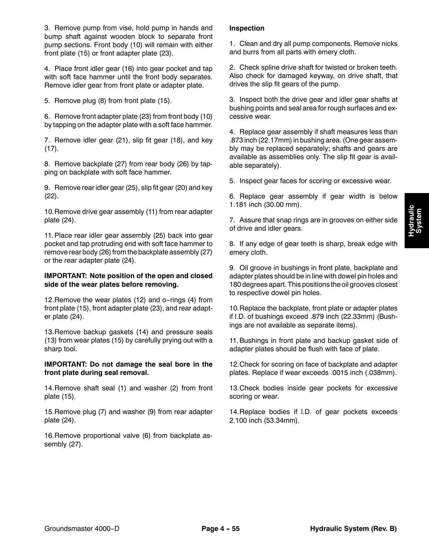
Inside the hydraulic chapter, the Toro Groundsmaster 4000-D service manual drills into the traction circuit, lower/raise cutting unit circuits, mow circuit, and steering circuit with dedicated flow diagrams. Testing is broken down into numbered procedures – traction circuit charge pressure, traction circuit relief pressure, cutting deck circuit pressure, cutting deck gear pump flow, cutting deck manifold relief pressure, cutting deck motor case drain leakage, steering circuit relief pressure, lift/lower circuit relief pressure, steering and lift/lower gear pump flow, counterbalance pressure, rear traction circuit (RV5) relief pressure, and the traction circuit reducing valve (PR) pressure. Service and repair coverage reaches every major hydraulic component: gear pump and piston (traction) pump – each with their own service sections – piston pump control assembly, the 4WD control manifold, deck drive manifold, cutting deck lift/lower manifold, filter manifold, flow divider, rear axle motor, front wheel motors, cutting deck motors, lift/lower control valve, steering valve, side deck and front deck lift cylinders, steering cylinder, hydraulic reservoir, and hydraulic oil cooler.
The Kubota Diesel Engine chapter documents the V2003-T Series engine used in the Groundsmaster 4000-D – a 4-cylinder, water-cooled, turbocharged diesel rated at 58 HP (43.3 kW) at 2600 RPM with 1999 cc (122.12 cu in.) total displacement. It covers engine removal, coupling disassembly and assembly, engine installation, air cleaner service, muffler and exhaust service, fuel tank service, radiator service, and the associated electrical connections on the engine. A separate Kubota Workshop Manual, Diesel Engine, V2003-T Series is referenced at the end of the chapter for deeper engine internal work.
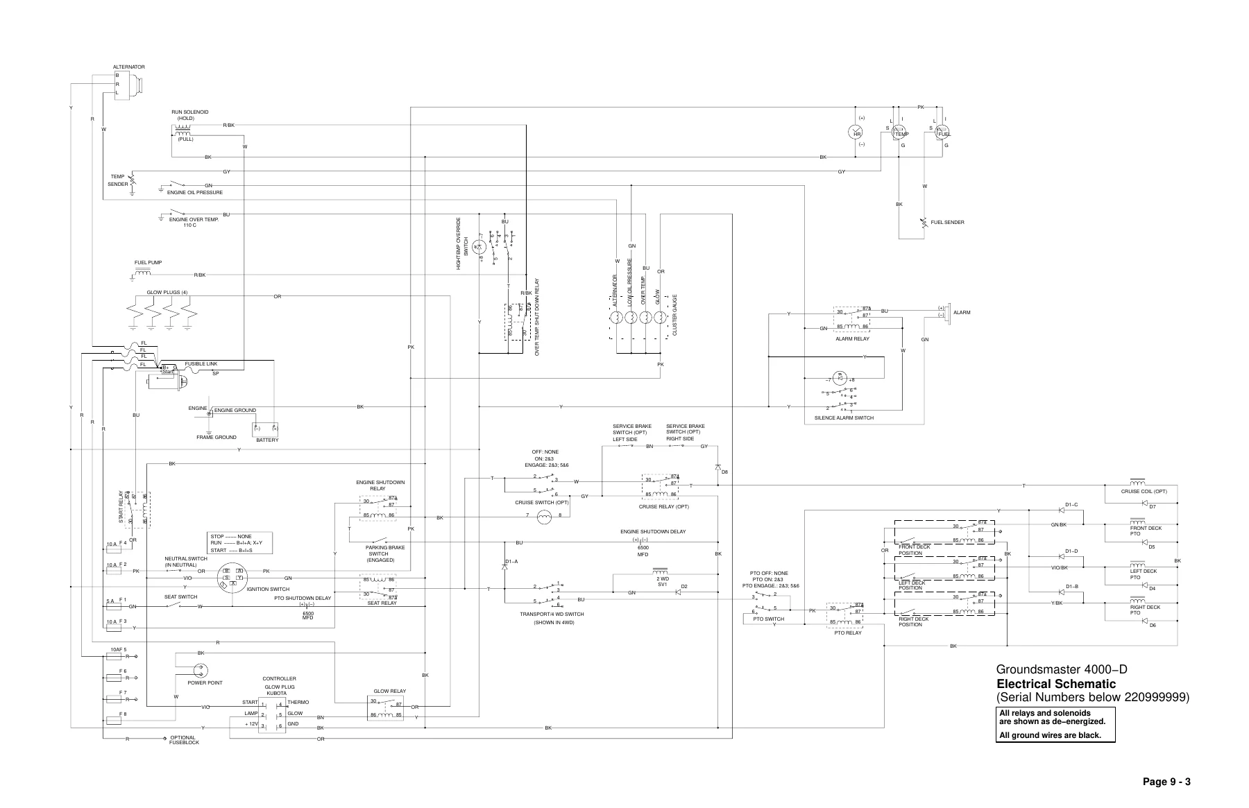
The electrical side of the Toro Groundsmaster 4000-D service manual includes the complete electrical schematic plus glow plug, crank, run (transport), and run (mow) circuit diagrams, main wire harness drawings for both early and later serial ranges, engine wire harness, and front wire harness drawings. Component testing procedures are provided for the ignition switch, fuses, warning lights, PTO switch, transport/alarm silence/temperature override switches, seat switch, parking brake switch, hour meter, audio alarm, relays, hydraulic valve solenoids, engine run solenoid, fuel sender, fuel gauge, fuel pump, glow controller, temperature sender, high temperature shutdown switch, temperature gauge, traction neutral switch, diode assemblies, diode circuit board, and cutting deck position switches. Battery storage, care, and service are covered in detail with specific gravity, charge rate, and load-test tables.
The axles, planetaries, and brakes chapter supports full teardown and rebuild work – rear axle assembly removal and installation, bevel gear case and axle case assembly with bushing-to-pin clearance and endplay measurements, differential shafts, axle shafts, input shaft/pinion gear service with bearing preload and shim selection, differential gear service with side gear and pinion gear clearance values, and pinion-to-ring gear engagement using the gear contact pattern method. Planetary wheel drive disassembly, inspection, and assembly procedures are also provided along with brake inspection and repair. The chassis chapter covers the steering tower, front deck lift arm, side deck lift arm, side deck rear arm assembly, lift arm yoke joint, and hood. The cutting units chapter covers the front cutting unit, side cutting unit, blade spindle service, and castor forks and wheels with a quality-of-cut troubleshooting matrix.
What This Toro Groundsmaster 4000-D Service Manual Enables
Owning the actual Toro Groundsmaster 4000-D service manual means you can stop guessing. Every hydraulic test has a pressure target and a step-by-step procedure, every fastener has a torque value, every clearance and backlash has a factory specification, and every electrical circuit has a schematic to trace faults against. Whether you are diagnosing a weak traction circuit, chasing an intermittent deck solenoid, rebuilding a front wheel motor, setting differential backlash, or pulling the Kubota engine for a coupling service, the procedures and specifications in this manual give you the exact path the factory-trained technician would take.
For a commercial mower that earns its keep, that is the difference between a quick, correct repair and an expensive repeat failure. Correct charge pressure, correct counterbalance setting, correct deck relief pressure, correct blade spindle preload and bearing setup, correct differential tooth contact – these are the details that keep a Groundsmaster 4000-D cutting clean and lasting long. The Toro Groundsmaster 4000-D service manual puts all of them in one document covering serial numbers below 220999999 and above 230000000 so you can match the procedures to the machine in front of you.
Delivered instantly as a PDF after purchase. No shipping, no waiting. Read it on a laptop in the shop, on a tablet next to the machine, or print the pages you need for the job. Keep a copy on every device you own.
IMAGES PREVIEW


Reviews
There are no reviews yet.