
Toyota 7FBEST10 7FBEST13 7FBEST15 Electric Forklift Repair Manual – CE 340-3
Original price was: $39.95.$24.95Current price is: $24.95.
Complete Toyota repair manual for 7FBEST10, 7FBEST13 and 7FBEST15 electric forklifts. Covers controllers, SAS, motors, brakes, hydraulics, masts, wiring diagrams and full troubleshooting with fault codes. Instant PDF download.
Description
Toyota 7FBEST10, 7FBEST13, 7FBEST15 Electric Forklift Repair Manual – CE 340-3
This Toyota 7FBEST10, 7FBEST13, 7FBEST15 electric forklift repair manual is the complete service documentation for the 1.0, 1.25 and 1.5 ton AC-powered counterbalance trucks. Published under document number CE 340-3, it covers every major system on these machines: the traction and pump logic units, the multi-display dashboard, the SAS (System of Active Stability), the battery pack, drive and pump motors, rear axle and drive unit, steering, brakes, hydraulic system, masts, cylinders and oil control valve. The manual runs to approximately 424 pages and is written for technicians who need to diagnose faults, carry out repairs and verify specifications to the correct tolerances.
File Details
- Manual type: Repair Manual
- Brand: Toyota
- Models covered: 7FBEST10, 7FBEST13, 7FBEST15
- Load capacities: 1.0 ton, 1.25 ton, 1.5 ton
- Control method: AC microcomputer controller
- Supply voltage: 24 V
- Document number: CE 340-3
- Language: English
- Page count: Approximately 424 pages
- File format: PDF
Chapters Covered
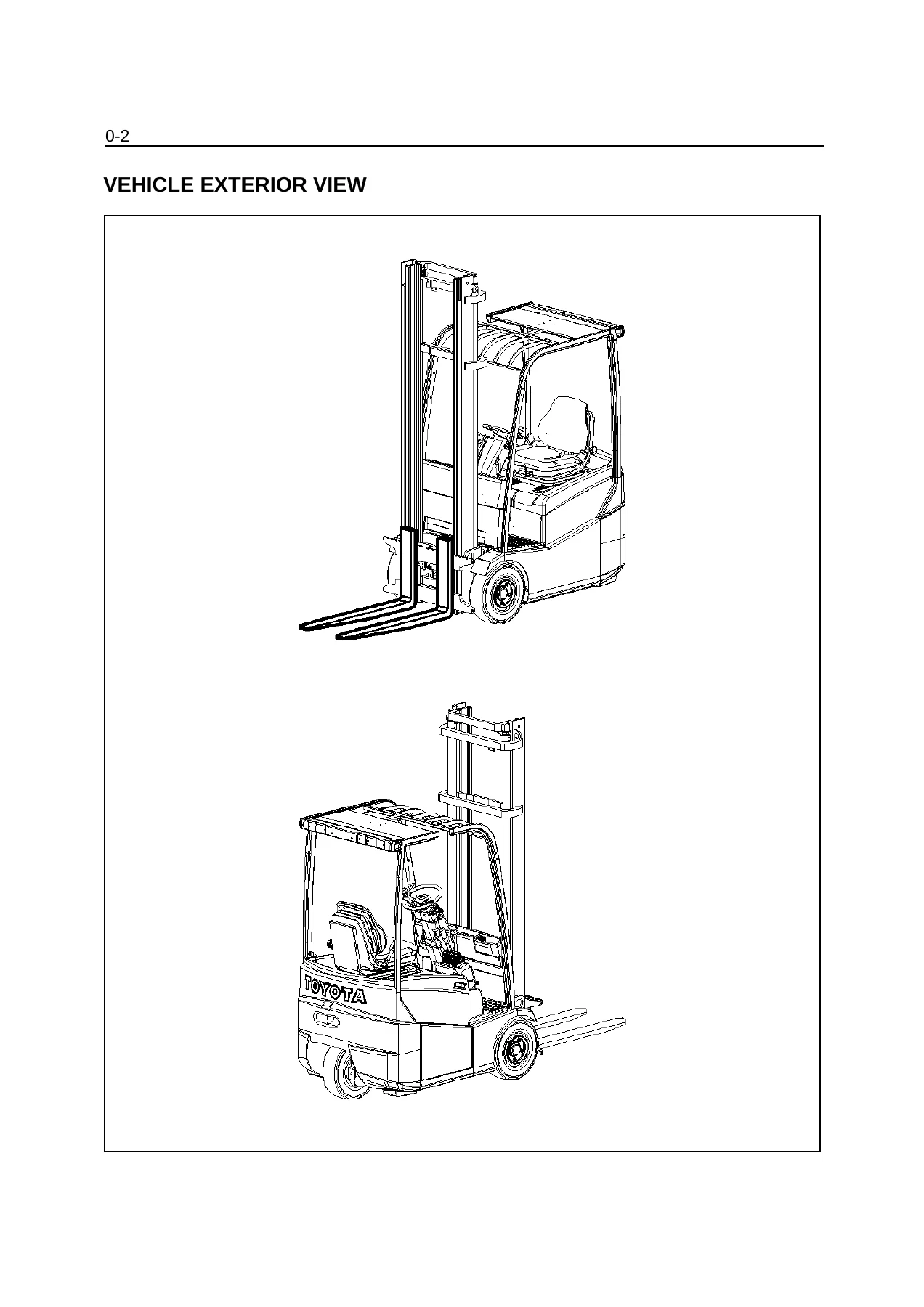
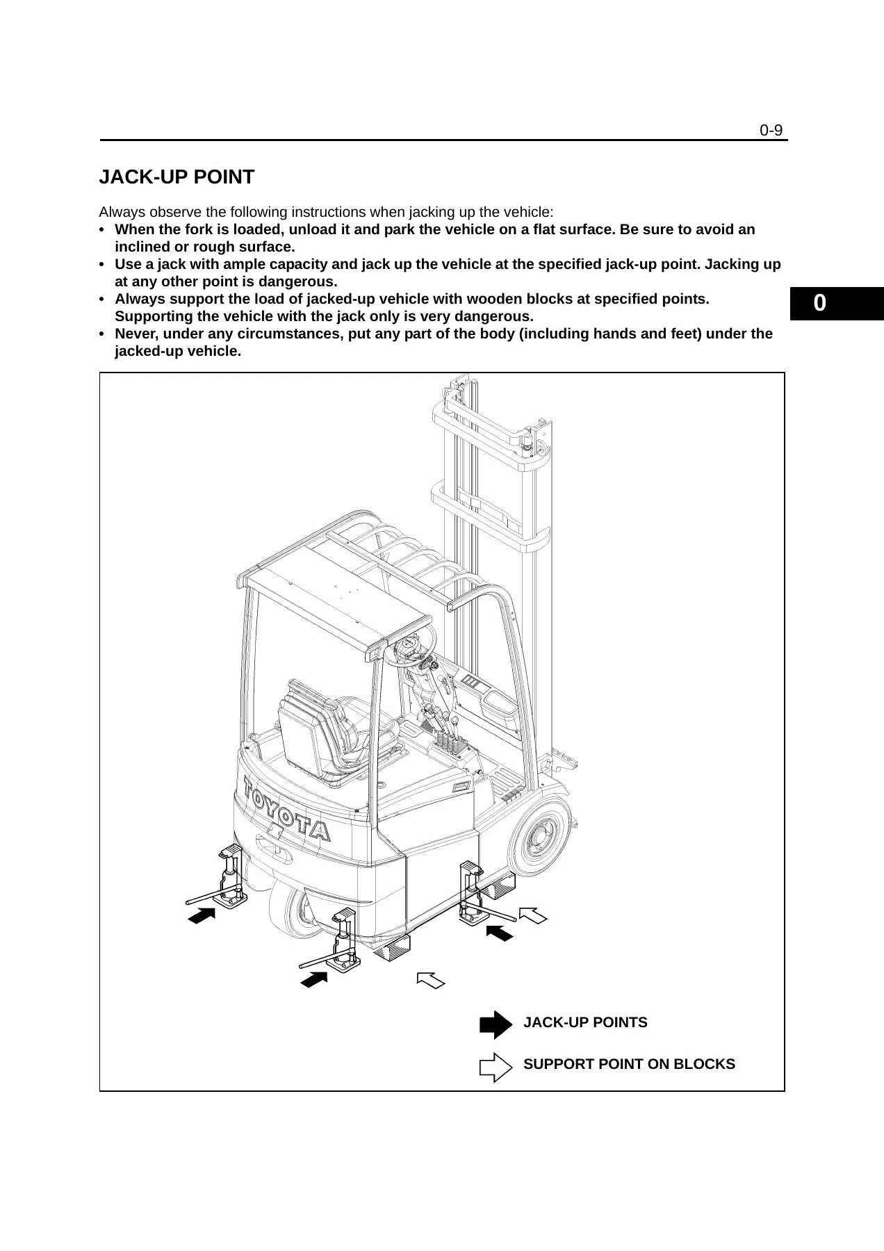
- General – Vehicle exterior views, model identification, frame number location, SI units, jack-up points, lifting and towing procedures, tightening torque tables, lubricant quantities, periodic maintenance tables, lubrication chart
- Battery – Battery compartment dimensions and required weights, service standards, charge indicator, vehicle behaviour with discharged and overdischarged battery, battery management, lead and gel battery parameter adjustment, troubleshooting, removal and installation, electrolyte inspection, specific gravity measurement, insulation resistance inspection
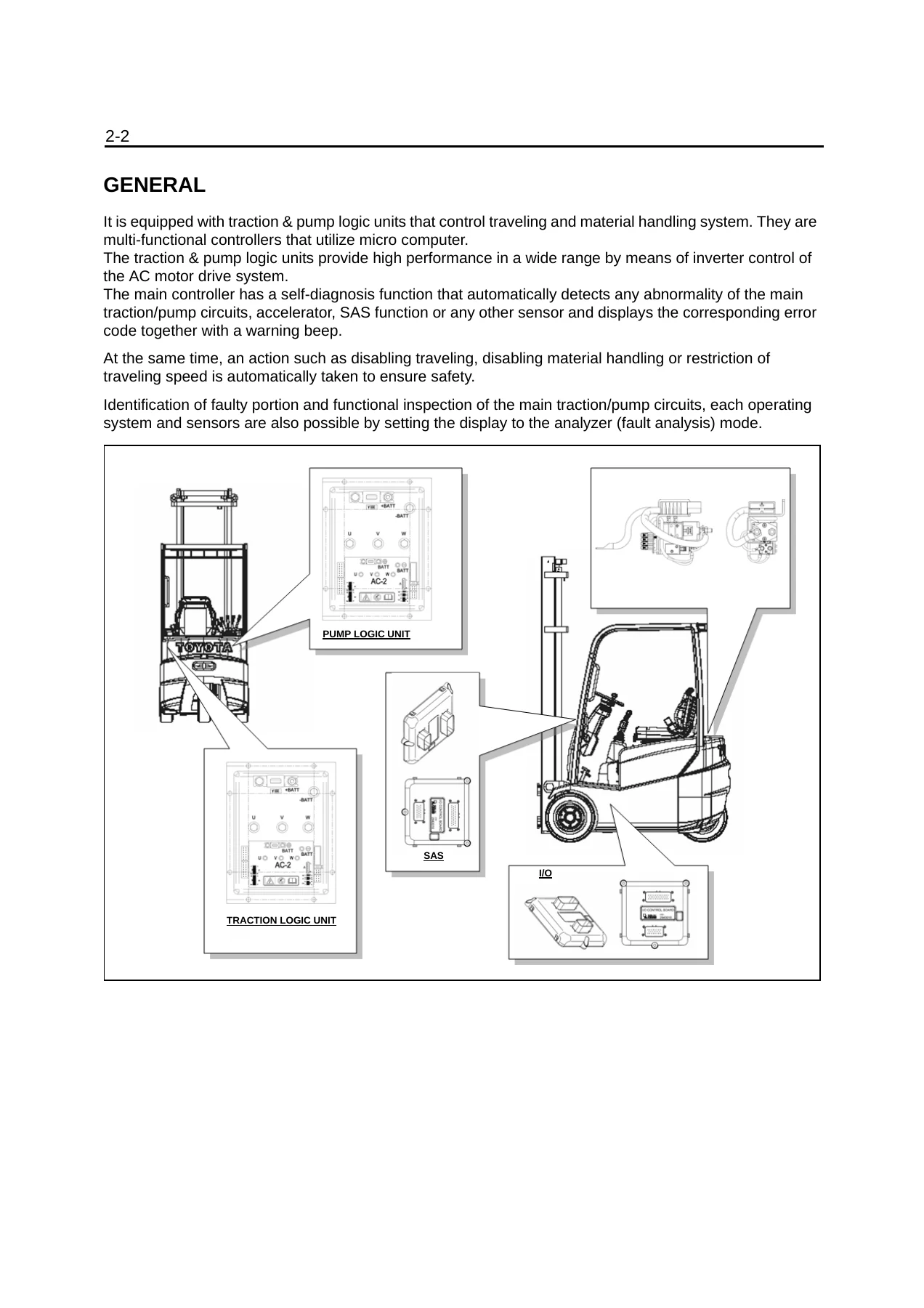
- Controller – Traction logic unit, pump logic unit, I/O control board, SAS control board, minilever MYRIO board, armrest board, main control unit, contactor panel, contactor group, display, direction switch, accelerator potentiometer adjustment, brake switch adjustment, parking brake adjustment, motor phase balancing checks
- Multi-Display Functions – User menu, power control, hour meter, date/time, speed reduction (turtle function), administrator menu, travel setting, PIN entry, truck management, service menu, analyzer, tuning, option, matching, ECT
- Troubleshooting – Connector handling, wire harness and connector inspection, system configuration with mechanic and electric control valves, complete diagnosis code list, error code procedures for traction logic unit, pump logic unit, Mhyrio logic unit, SAS control board, armrest board, dashboard and I/O control board
- Motor – Drive motor general and specifications, encoder, traction encoder removal, traction temperature sensor removal, pump motor general and specifications, encoder replacing, temperature sensor replacing
- Rear Axle & Drive Unit – General, specifications, components, steering hydraulic motor, steering potentiometer, steering system, hydraulic motor removal and installation, rear axle and drive unit removal and installation
- Steering – Power steering system general and specifications, components, hydrostatic steering valve troubleshooting, power steering removal and installation, relief pressure inspection and adjustment, priority valve
- Brake – Brake system general and specifications, components, parking brake, brake pedal, front brake, brake group, brake shoes and brake cylinder, brake pedal adjustment, brake circuit bleeding, parking brake adjustment
- Body & Frame – Components, battery cover, counterweight, operator’s seat, fuses, fuse installation locations, fuse names and capacities
- Material Handling System – Hydraulic circuit for mechanic and electric control valves, components, steering system, hydraulic system, V/FV/FSV masts, hydraulic oil and filter, natural drop test, oil leak test, lifting cylinders, tilting cylinders
- Mast – V mast components, fork carriage, chain and chain wheel, mast and fork carriage rollers, mast chains, fork inspection, FV and FSV mast components, fork carriage, chain and chain wheel
- Cylinder – Lift cylinder general, specifications, components, side/rear cylinder, central cylinder, flow regulator valve, mast performance tables, tilt cylinder general, specifications, components
- Oil Pump – General, components, service pump removal and installation, test method, mast performance table
- Oil Control Valve – Mechanic oil control valve (3 and 4 levers, with and without hand direction lever), hydraulic circuit, relief valve adjustment, mast performance tables, lift locking screw, control valve lever, electric oil control valve for minilever and joysticks, minilever components, joystick, lever
- SAS Functions – SAS system general, components, traction encoder, steering knob synchronizer valve, steering encoder, lifting height switch positions, tilt angle sensor, load sensor, repair work precautions, matching procedures, vehicle standard state, cautions on modifying vehicles
- Main Options – Svanslos system electric diagram, optional devices electric diagram
- SST List – Special service tool list, service standards
- Appendix – Auxiliary wiring harness, connectors, working lights wiring harness, front and rear combi-lights, rear combi-lights, armrest, lighting equipment, flashing beacon, steering column, rear window heated, windscreen wiper, Svanslos system wiring harness, electric diagrams
The manual is structured for practical shop use. Each system chapter opens with general information and specifications before moving into component-level removal, inspection and installation procedures. Torque values appear alongside the relevant steps, and exploded assembly drawings show the order of disassembly. The troubleshooting chapter is particularly detailed: it lists every diagnostic code the controllers can produce, explains the condition that triggers each code, and gives step-by-step checks to isolate the fault to a specific component or wiring circuit. The controller chapter includes connector pin-out tables with wire colours and expected voltages, so signal-level faults can be traced with a multimeter. The SAS chapter explains how the active stability sensors interact with the mast and steering systems, and the matching procedures required after replacing sensors or related parts. The appendix reproduces the wiring harness layouts and full electric diagrams for the base truck and its options.
What This Manual Enables You to Do
With this repair manual, a technician can carry out the full range of service work on the 7FBEST10, 7FBEST13 and 7FBEST15 forklifts. That includes reading and clearing fault codes from the traction and pump logic units, diagnosing CAN bus communication problems between the controller boards, testing motor phase balance, checking encoder signals, adjusting the accelerator potentiometer and brake switches, servicing the rear axle and drive unit, rebuilding the brake group, replacing hydraulic motors and steering potentiometers, overhauling lift and tilt cylinders, adjusting mast chains and rollers, and setting the relief pressures on the oil control valve. The periodic maintenance tables give the inspection intervals for daily, weekly, 6-week, 3-month, 6-month and annual checks, along with the replacement schedule for hydraulic oil, filters, brake fluid, hoses and chains.
The value of having the correct procedures and specifications is hard to overstate on a machine like this. The controllers on these trucks store error codes that point directly to the faulty circuit, but only if you know what each code means and how to test the associated components. The SAS system in particular requires matching procedures after any sensor replacement, and skipping them can leave the truck in a restricted operating mode. Torque values for critical fasteners – counterweight bolts, mast mounting bolts, cylinder components, brake drums – are listed in the relevant chapters, and getting them wrong can lead to premature failure or a safety hazard. The manual also covers the correct sequence for bleeding the brake circuit, the natural drop test for lifting, the oil leak test for tilting cylinders, and the chain wear limits.
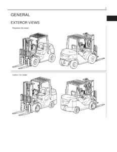
IMAGES PREVIEW
This Toyota forklift repair manual is supplied as a PDF file, available for instant download after purchase. There is no shipping to wait for and no physical book to keep track of in the workshop. You can open it on a laptop or tablet at the machine, print the pages you need for a particular job, and keep the full document on file for future reference. Whether you are a fleet maintenance technician, an independent forklift mechanic, or an owner-operator who prefers to handle your own repairs, this manual provides the procedures and specifications required to keep these Toyota electric forklifts running correctly.
Reviews
There are no reviews yet.