
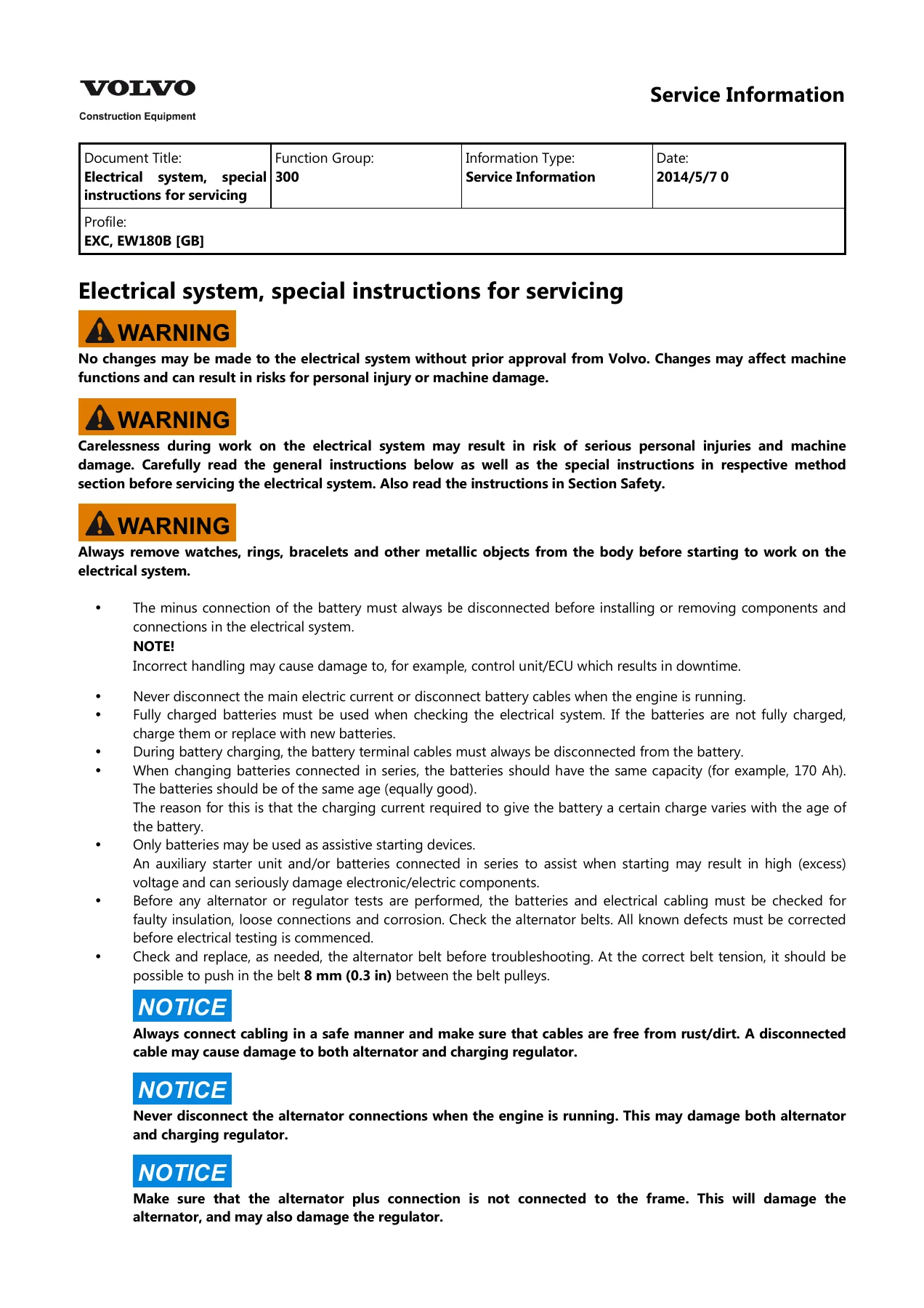
Volvo EW180B Electrical System Service Information Manual PDF 2014
Original price was: $34.95.$19.95Current price is: $19.95.
Volvo EW180B Electrical System Service Information manual PDF covering data buses, ECUs, error codes, wiring diagrams, measuring conditions, battery and charging, start circuit, wipers, fuses, relays, VCADS Pro tests, and service display unit diagnostics. This 2014 service information is written for EXC, EW180B [GB] and provides practical electrical troubleshooting and repair reference material.
Description
Volvo EW180B Electrical System Service Information Manual PDF 2014
The Volvo EW180B Electrical System Service Information Manual PDF 2014 is a targeted service information document for the Volvo EW180B wheeled excavator in the EXC, EW180B [GB] profile. It covers electrical system servicing, electronic control system design, data bus communication, control unit functions, fault tracing, error code interpretation, wiring diagrams, component lists, and many of the electrical components and switches used on the machine. This is the 2014 service information release, dated 2014/5/7, function group 300.
File Details
- Manual type: Electrical system service information
- Document title: Electrical system, special instructions for servicing
- Function group: 300
- Brand: Volvo
- Model: EW180B
- Profile: EXC, EW180B [GB]
- Language: English
- Page count: 391
- File format: PDF
- Date: 2014/5/7
Chapters Covered
- Electrical system, special instructions for servicing
- Electrical system, description
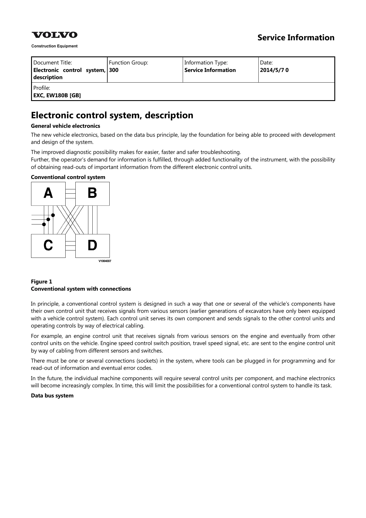
- Electronic control system, description
- Data bus system
- Communication with data buses
- CAN/J1939 control bus
- J1708/J1587 information bus
- Data buses, function
- Messages and information content
- Identification numbers: MID, PID, PPID, SID, PSID, FMI
- Service connection and programming connection
- Engine control unit E-ECU, function description
- Instrument control unit I-ECU, function description
- Transmission control unit T-ECU, functional description
- Vehicle control unit V-ECU, function description
- Data links, fault tracing with Oscilloscope
- Troubleshooting, general
- Collection of basic data
- Troubleshooting tools
- VCADS Pro service tool
- Special tools for troubleshooting
- Troubleshooting using alarm and error codes
- Troubleshooting strategy
- Electrical cables and connectors, checking
- Error texts and troubleshooting information, general
- SAE error codes, translation to error messages, general
- Error codes, overview
- MID 128 E-ECU error codes and individual code sections
- MID 130 T-ECU error codes and individual code sections
- MID 140 I-ECU error codes and individual code sections
- MID 187 V-ECU error codes and individual code sections
- E-ECU active and passive measuring conditions
- T-ECU passive measuring conditions
- V-ECU active and passive measuring conditions
- Pressure switch test with VCADS Pro
- Fan motor control test with VCADS Pro
- Battery, description, storage and charging
- Charging, description
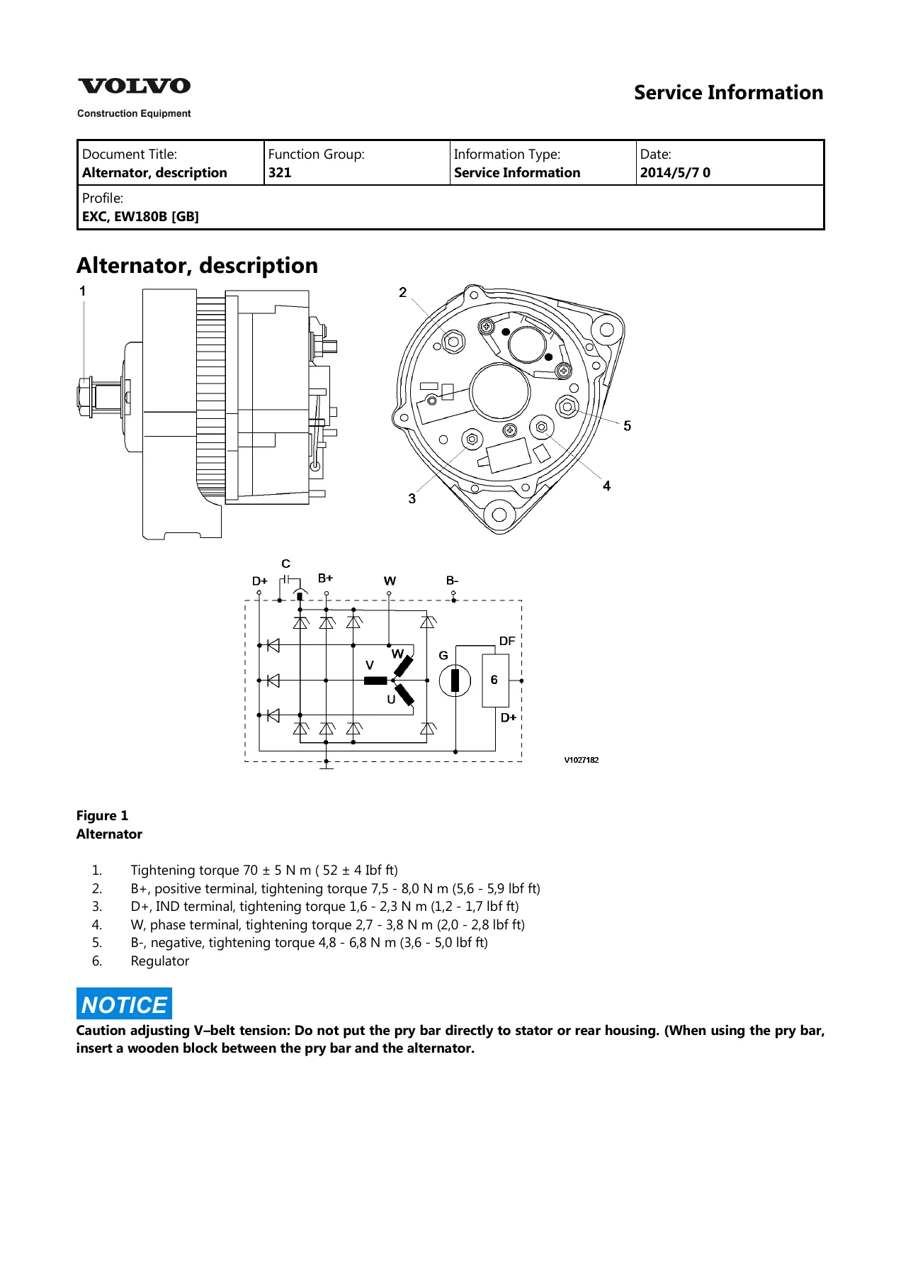
- Alternator, description
- Start circuit, description
- Preheating, description
- Electric horn, description
- Windscreen wiper, description and components location
- Wiper controller, upper wiper motor, lower wiper motor
- Window limit switch, description
- Battery disconnect switch, description
- Emergency engine speed control switch, description
- Auto/manual select switch, description
- Main switch, description
- Start switch, description and specifications
- Multi-function lever switch, description
- Solenoid valves and proportional valves descriptions
- Connectors
- Control units changing, precaution
- ECU replacement procedures for E-ECU, T-ECU, I-ECU, V-ECU
- Grounding points, position
- Wiring diagram, component list and index
- Component designations, cable and component marking explanations
- Electrical symbols and designations
- Wiring diagrams 1 through 25
- Electrical distribution box, fuses and relays
- Hour counter description
- Sensor descriptions
- Service display unit description, general, engine, electrical system, hydraulics, self-diagnostics
- Radio and DC-DC converter descriptions
What This Volvo EW180B Electrical Service Information Provides
The Volvo EW180B Electrical System Service Information Manual PDF 2014 goes well beyond a simple fuse chart. It explains how the machine’s electronic control system is built around data bus communication, with control units connected over CAN/J1939 and J1708/J1587 links. You get function descriptions for the E-ECU engine control unit, I-ECU instrument control unit, T-ECU transmission control unit, and V-ECU vehicle control unit. The manual describes what each control unit monitors and controls, how service connections and programming connections are used, and how the service display unit and VCADS Pro can be used to read error codes, test components, and access machine information.
For hands-on electrical diagnosis, the document includes detailed error code sections organized by MID and SAE code structure. It explains MID, PID, PPID, SID, PSID, and FMI identification numbers and provides error code overviews for E-ECU, T-ECU, I-ECU, and V-ECU. Individual code pages give symptoms, possible causes, and test measuring values. This makes the Volvo EW180B Electrical System Service Information Manual PDF 2014 a strong reference when tracing faults such as open circuits, short circuits to ground, short circuits to voltage, sensor failures, communication errors, relay faults, and solenoid valve failures.
The manual also includes oscilloscope fault tracing for data links, with reference and error examples for J1939 H/L and J1708/1587 A/B. That material helps a technician understand what a healthy data bus signal looks like and what changes when resistance, short circuits, or communication faults are present. In addition, the electrical cables and connectors checking section describes open circuit testing, short-circuit testing, contact resistance and oxidation checks, and connector pin and sleeve cleaning.
Practical Systems and Components Covered
Beyond the control system and diagnostics, this service information covers many electrical systems and components on the EW180B. You will find battery description, storage, charging, and battery replacement information, along with charging circuit and alternator description and replacement. The start circuit, preheating, electric horn, windscreen wiper, wiper controller, upper and lower wiper motors, and window limit switch are all described. Switches such as the battery disconnect switch, emergency engine speed control switch, auto/manual select switch, main switch, start switch, and multi-function lever switch are included with descriptions and, where applicable, specifications.
Solenoid valves and proportional valves are also documented, including cruise control, travel, gear select, Q-max, parking brake, hammer, power boost, control lockout, quickfit, boom float, rotator, axle locking, outrigger, and various proportional valve functions. The electrical distribution box section lists fuses and relays with wiring diagram references, making it easier to locate the correct circuit before testing. Wiring diagrams 1 through 25 provide circuit routing, cable designations, component designations, and connector references. Component designations, cable and component marking explanations, electrical symbols, and grounding points are included to help interpret the diagrams correctly.
Diagnostics, Testing, and ECU Service
The Volvo EW180B Electrical System Service Information Manual PDF 2014 is especially useful for structured troubleshooting. It begins with troubleshooting strategy, basic data collection, and troubleshooting tools, then moves into alarm priority and error message handling. The measuring conditions tables for E-ECU, T-ECU, and V-ECU give pin-level reference values for active and passive testing. This supports accurate diagnosis before replacing components. The manual also includes VCADS Pro test procedures for pressure switch tests and fan motor control tests, with general test conditions, procedures, and evaluation notes.
Control unit replacement is covered for E-ECU MID 128, T-ECU MID 130, I-ECU MID 140, and V-ECU MID 187, including both pre-programmed and non-programmed ECU change procedures. The precautions for changing control units are also stated. This is important because electrical system work on the EW180B can involve programming, parameter saving, and connector handling that must be performed correctly. The service display unit section describes how to read stored information, change settings, and reset logged values, with display groups for engine, electrical system, hydraulics, and self-diagnostics. That gives technicians another way to access diagnostic information when a VCADS Pro computer is not connected.
Who This Manual Is For
This document is aimed at technicians, electricians, and service personnel who work on the Volvo EW180B wheeled excavator and need electrical system service information. It is also useful for owners and operators who want a deeper understanding of the machine’s electrical architecture, error code reporting, data bus communication, and component locations. The content is technical and assumes familiarity with electrical measuring tools, wiring diagrams, and service procedures. It is not a basic operator’s manual; it is service information for diagnosing and repairing the electrical system.
Why the Volvo EW180B Electrical System Service Information Manual PDF 2014 Matters
Electrical faults on modern construction equipment can be difficult to isolate without the right reference. The Volvo EW180B Electrical System Service Information Manual PDF 2014 gives the correct control unit identification, data link behavior, error code translation, pin-level measuring values, and wiring diagram references needed to troubleshoot accurately. Instead of guessing at connectors, relays, fuses, or sensor circuits, you can follow the documented test methods and compare readings against the listed reference values. That saves time, reduces unnecessary parts replacement, and helps avoid damage to sensitive electronic components.
Because the manual includes both passive and active measuring conditions, it supports testing with the machine off as well as testing with power supplied. The error code sections connect SAE codes to Volvo error texts, helping you move from a displayed code to a specific component or circuit. The wiring diagrams and component lists help you locate the correct harness, connector, fuse, relay, and ground point. For anyone maintaining or repairing an EW180B, this service information is a practical electrical troubleshooting resource.
Get Instant Access
IMAGES PREVIEW
This Volvo EW180B Electrical System Service Information Manual PDF 2014 is delivered as an instant PDF download after payment. There is no shipping and no waiting for a physical book. You can open it on a computer, tablet, or smartphone, and print the pages you need for the workshop. Whether you are diagnosing a data bus fault, checking a sensor circuit, replacing an ECU, tracing a fuse or relay circuit, or reading error codes with VCADS Pro or the service display unit, this manual gives you the Volvo EW180B electrical service information in a convenient digital format.
Reviews
There are no reviews yet.