
Volvo FL Truck Wiring Diagrams 2013 – Complete Electrical Schematics PDF Manual (89128816)
Original price was: $59.95.$39.95Current price is: $39.95.
Complete Volvo FL truck wiring diagram manual, order 89128816, Release 01, September 2013. Full electrical schematics, connector pin-outs, ground points, wire numbering, component lists and cab/harness illustrations for CHID B669174-. Instant PDF download.
Description
Volvo FL Truck Wiring Diagrams – 2013 Release 01
This is the complete Volvo FL truck wiring diagram manual, order number 89128816, Release 01, published September 2013. It covers chassis range CHID B669174- and provides the full electrical schematics, connector pin-outs, ground points, wire numbering and component lists needed to trace, diagnose and repair the electrical system on Volvo FL vehicles built from that chassis ID onward.
File Details
- Manual type: Wiring diagram / electrical schematics manual
- Brand: Volvo
- Model: FL
- Language: English
- Page count: 226 pages
- File format: PDF
- Order number: 89128816
- Release: 01
- Date: September 2013
- Chassis coverage: CHID B669174-
Chapters Covered
- Foreword
- Example of wiring diagram
- Wire numbering
- Starting switch
- Wiring diagram AK – Main power supply
- Wiring diagram CLU20 – Engine D8, EM-EU6
- Wiring diagram FC – AIR Power Management, BBOX-L
- Wiring diagram GF
- Wiring diagram IR – 12V power supply
- Wiring diagram IF1 – Heated adjustable mirror LHD
- Wiring diagram XE – Backbone 2
- Illustrations index
- List of connectors
- Ground connections
- List of wiring numbers
- List of components
- Abbreviations
- Cable colour code
Foreword and How to Read the Diagrams
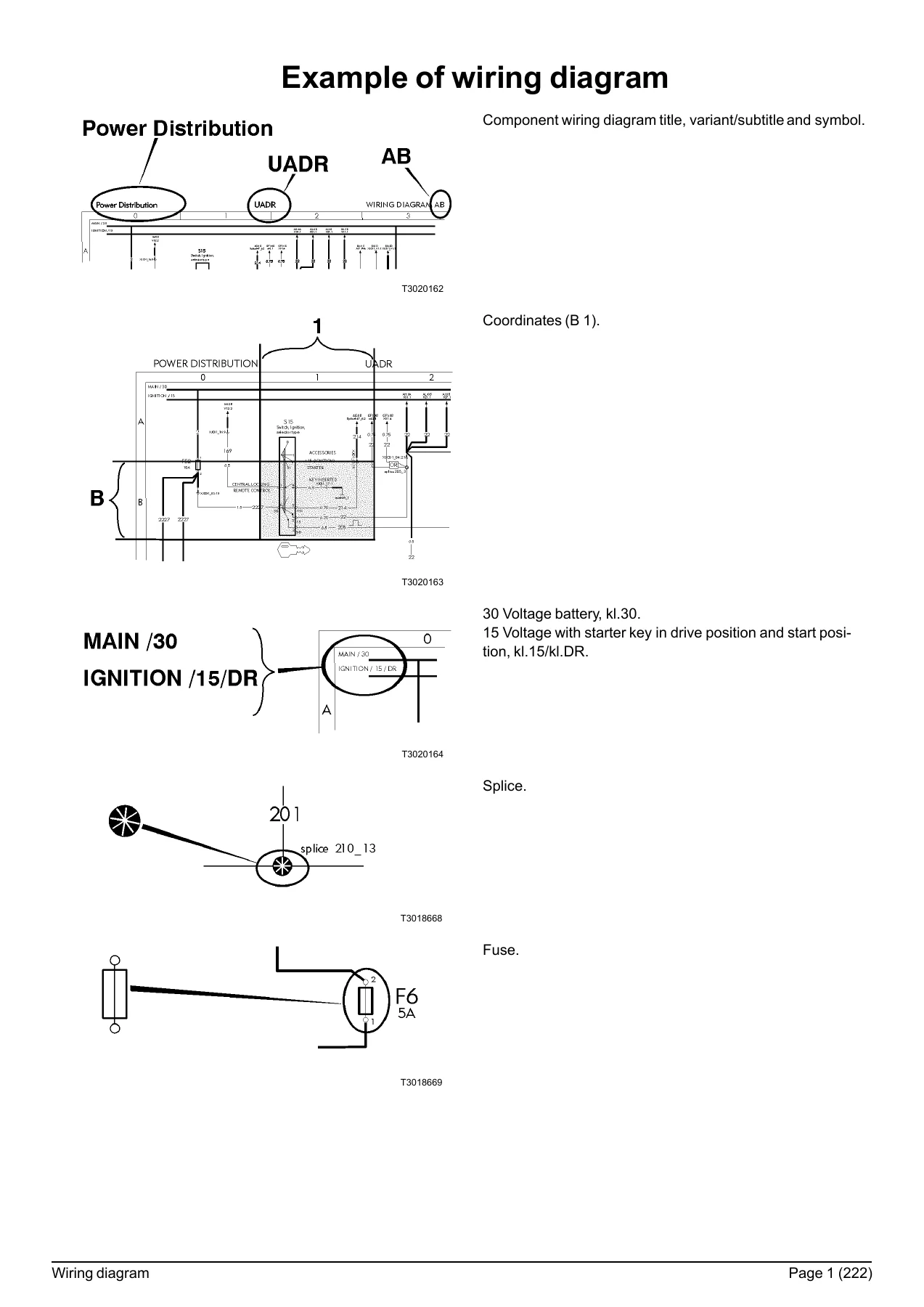
The manual opens with a foreword explaining that the descriptions and service procedures are based on designs and methods studies carried out up to September 2013, and that vehicles built after that date may have different specifications. The symbol key that follows is the key to reading every sheet: it explains how component wiring diagram titles, variant/subtitles, coordinates (for example B 1), splices, fuses, switches, relays, conductor-on-circuit-card notation, thin wire lines, connector numbering (EJB connectors, pass-through connectors, others), the exclusive OR (OR) symbol, and ECU input/output symbols are drawn. ECU symbols cover digital output low (set to ground), digital output high (set to 24V/5V etc.), ECU ground, analog input, active low, active high, and the 120 ohm CAN bus ending resistance. Wire numbers are also explained, including the equipotential property and the first-digit family table: 1 ground and negative supply, 2 positive supply, 3 signal, 4 comfort accessories, 5 security accessories, 6 lighting, 7 instrumentation, 8 body builder, 9 free, 0 electronic/data link. The starting switch logic diagram is included as well.
Main Power Supply (Wiring Diagram AK)
This section covers the main power supply circuits on the FL. It shows the feed from MAIN /30 and IGNITION /15/DR through fuse positions F24, F26, F48, F49, F66, F73, F80, F92, F94, F100, F102, F107 and F109 to the components they protect, including the key switch, immobiliser, wiper IC, flasher, FMS gateway, FMS connector, EBS, EBR, main EBR space, diagnostic, TPM ECU and APM. Fuse ratings and the specific wire numbers (2231, 2227, 2233, 2230, 2316, 2312, 2303, 2304, 452, 719 and others) are printed on the sheet, along with the corresponding coordinate references used to cross-reference other diagrams.
Engine D8, EM-EU6 (Wiring Diagram CLU20)
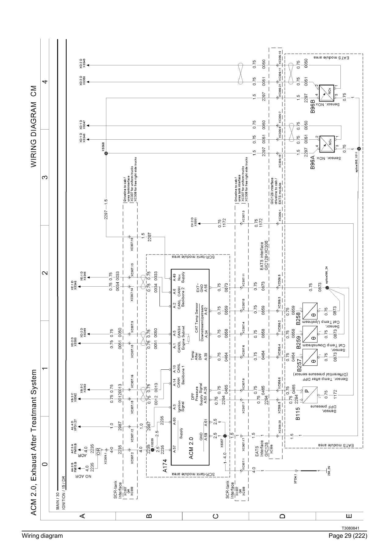
The CLU20 sheets cover the Engine D8, EM-EU6 electrical system. They show the ACM 2.0 (A174) control unit and its inputs and outputs, the EATS module area, and the sensors and actuators on the engine, including the camshaft sensor (B05), crankshaft sensor (B04), boost pressure and temperature sensor (B37), EGR differential pressure sensor (B166), high rail pressure sensor (B222), aftertreatment fuel pressure sensor (B187), coolant high temperature sensor (B231), oil pressure sensor (B118), oil level/temperature sensor (B119), turbo speed sensor (B87), NOx sensors (B96A/B96B), DPF temperature sensor, and the injectors Y33A through Y33F, Y144A/Y144B Jacobs valves, Y54 VGT, Y142 M-PROP HP pump, Y143 PRV, Y103 safety valve and Y114 throttle. ACM connector pin-outs, engine subnet (Euro6) and CAN wiring, and the EATS module area are all drawn.
Air Power Management, BBOX-L (Wiring Diagram FC)
The FC sheet covers the Air Power Management control unit (A63) and the battery box left-hand side (BBOX-L) circuits. It shows the compressor, the air dryer, the front brake, rear brake, trailer brake and park brake circuits, the trailer brake test connection, and the feeds through fuse positions F57, F68, F69, F70 and others. Connector XC309, the BBOX main fuses (FM15), the pre-heating relay and the associated ground points are drawn with their wire numbers and coordinates.
12V Power Supply (Wiring Diagram IR)
The IR sheet covers the 12 V power supply circuits. It shows the voltage converters U06R10 (10A) and U06R15 (15A), the 24 V and 12 V sockets X22D, X23, X24D and X44 (cubic storage), the Citizen Band unit (A73), the pack office (A101), and the feeds through fuse positions F96, F105, F106 and F108. The 24 V and 12 V socket wiring, grounds and distribution are drawn with their wire numbers and coordinates.
Heated Adjustable Mirror LHD (Wiring Diagram IF1)
The IF1 sheet covers the left-hand-drive heated adjustable mirror circuits. It shows the mirror switch (S123), the mirror adjustment switch (S103), the heated mirror relay (K04), the mirror motors R02D and R02P, the door harness, and the feeds through fuse positions F13 and F66. The mirror adjustment motor control wires (428, 430, 432), the heated mirror power supply, the door switch control and the instep lights control are all drawn with their coordinates.
Backbone 2 (Wiring Diagram XE)
The XE sheet covers the Backbone 2 data bus. It shows the SCR-bank interface, the ACM, the engine interface connector and the EATS module area, with the Backbone 2 bus high and low wires (0033 and 0034) running between the engine interface and the SCR-bank interface. The subset for the ADBLUE tank on the left frame and the subset for the ADBLUE tank on the right frame are drawn, along with the chassis harness routing.
Component Location Illustrations
The illustrations index and the illustrations that follow show the physical location of the connectors, components and harnesses on the vehicle. They are organised by area and by cab variant:
- Antenna
- Battery connections
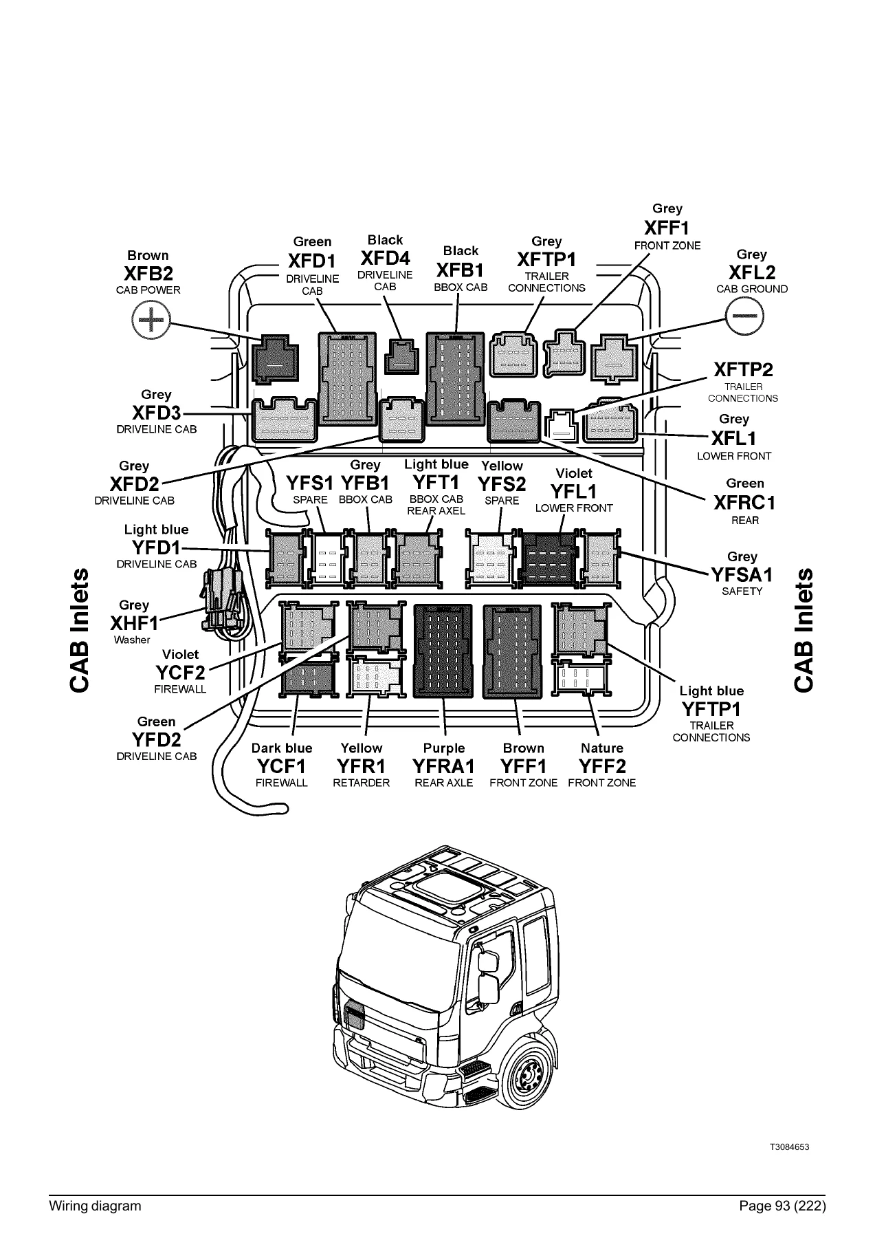
- Cab inlets
- ECU in cab
- Electrical junction box
- Switches
- Wiring harness, instruments
- Wiring harness, roof
- Wiring harness, floor
- Wiring harness, engine
- Wiring harness, frame
- Wiring harness, roof beacon light
- Wiring harness, chassis
- Wiring harness, trailer connections
- Wiring harness, door
- Wiring harness, main switch
- Wiring harness, bumpers
- Wiring harness, cab-battery box
- Wiring harness, gearbox
- Wiring harness, upper front
These pages include the LHD and RHD driver and passenger cab layouts, the steering wheel layout, the 1006 and 1007 roof and floor layouts, the 1030 D5 and D8 engine layouts, the 1057B EASPS ADTP-R EM-EU6 layout, the 1083 door layouts, the 1435 and 1460 battery box layout, the 1447 front layout and the 1501 main switch layout.
Connector, Ground, Wiring and Component Lists
The reference lists at the back of the manual are what make fault-finding practical. The List of Connectors gives the pin-out, circuit function, wiring number and diagram coordinate for every connector in the truck, including ICBB1, ICR1, PB3, X02, X03, XADH01, XADH02, XAHH1, XAHH2, XAHR1 through XAHR4, XC301 through XC323, XCI1 through XCI3, XCIF1, XCIN1, XCIN2, XCIO1, XCIO2, XCIR1, XCIS1 through XCIS3, XCR3 through XCR12, XCRH, XFD1 through XFD3, XFL1, XFL2, XFTP1, YCF1, YCF2, YFB1, YFD1, YFD2, YFF1, YFF2, YFL1, YFRA1, YFT1 and YFTP1. The Ground Connections list gives every ground point with its coordinate. The List of Wiring Numbers indexes every wire number to its diagram coordinate. The List of Components covers the control units, sensors, lamps, motors, relays, switches, valves and other hardware (A03MV through Y146). The Abbreviations list explains the acronyms used throughout, and the Cable Colour Code lists the wire colours used in the engine and transmission harnesses.
Why This Volvo FL Wiring Diagram Manual Matters
Electrical faults on a modern truck are rarely obvious. A single chafed wire, a corroded ground point, a failed relay or a mis-pinned connector can shut down a circuit that shares nothing else with the symptom. Without the correct schematic you are left tracing by guesswork, pulling harnesses apart and hoping the fault shows itself. This manual removes the guesswork. Every circuit is drawn, every connector is pinned out, every wire is numbered, and every component is listed with the diagram coordinate that tells you exactly where to look.
With this manual you can:
- Trace any circuit on the Volvo FL from the battery through the main power supply, fuses, relays and connectors to the component and back to ground.
- Read connector pin-outs for the EJB, cab, engine, chassis, gearbox, trailer and body-builder interfaces.
- Identify the correct wire number, colour, gauge and equipotential for every conductor in the harnesses.
- Diagnose the Engine D8 EM-EU6 management system, the ACM 2.0, the EATS and SCR circuits, the air power management system, the EBS, the ECS, the parking heater, the immobiliser, the tachograph, the FMS gateway and the rest of the FL electrical architecture.
- Locate every ground point on the vehicle and verify the ground path before condemning a component.
- Match the physical connector on the truck to the correct pin-out using the cab inlet and harness illustrations.
- Cross-reference between diagram sheets using the coordinate system (for example B 1, AK:4 B, IF1:2 C) so you can move from a component to the circuit that feeds it without hunting.
This is the same wiring information used in the workshop. It is not a generic diagram collection, it is the FL-specific document, with the FL’s own connector designations, wire numbers, fuse positions and chassis coverage. Whether you are an independent workshop, a fleet maintenance department, a body builder integrating equipment onto an FL chassis, or an owner who prefers to understand the truck before handing it over, having the correct schematics on hand turns an open-ended electrical fault into a systematic test.
IMAGES PREVIEW
The manual is delivered as an instant PDF download. There is no shipping, no waiting, and no physical book to lose. Open it on a laptop in the workshop, a tablet in the cab or a phone at the side of the road. Print the sheets you need for the job and mark them up as you work. If you work on more than one FL, the file stays with you for every job.
Reviews
There are no reviews yet.