
Volvo VM EM-EU5 Wiring Diagrams 89166768 Release 02 Truck Electrical Manual PDF
Original price was: $39.95.$24.95Current price is: $24.95.
Complete Volvo VM / EM-EU5 wiring diagram manual, order number 89166768, Release 02 (May 2014). Covers engine ECU, I-Shift, SCR/AdBlue, ABS, lighting, cab and chassis harnesses, plus fuse, relay, connector and component lists with colour codes.
Description
Volvo VM / EM-EU5 Wiring Diagrams — Order 89166768, Release 02
This is the wiring diagram manual for the Volvo VM and EM-EU5 trucks, published under order number 89166768, Release 02, with designs and service procedures studied up to May 2014. It is a chassis identification CHID E149891- document, issued by Volvo Truck Corporation, Curitiba, Brazil. Everything inside is organised for one job: tracing, testing and repairing the electrical system of these vehicles using the exact circuit paths, connector pins and cable colours the truck was built with.
File Details
- Manual type: Wiring diagrams / electrical service documentation
- Brand: Volvo
- Models: VM, EM-EU5
- Order number: 89166768
- Release: Release 02
- Date: May 2014
- Chassis identification: CHID E149891-
- Language: English
- Page count: 118
- File format: PDF
Chapters Covered
- Contents of wiring diagrams
- Wiring diagrams
- Illustrations index
- Illustrations
- List of fuses
- List of relays
- List of connectors
- List of components
- Colour codes of electrical cables
Wiring Diagrams
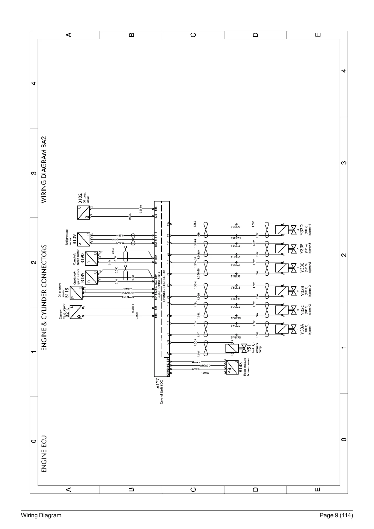
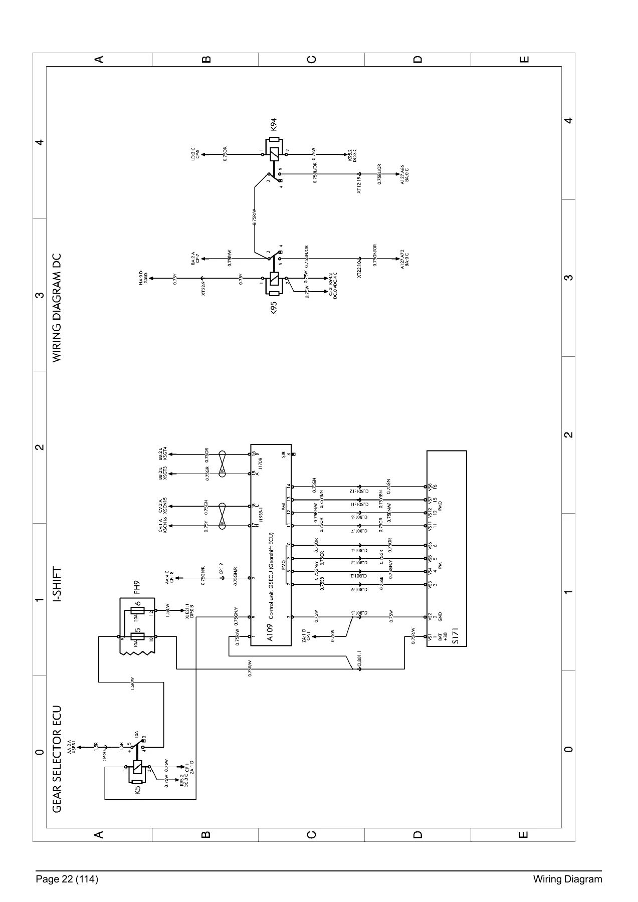
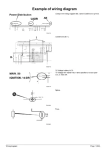
The core of the manual is a set of full-page circuit diagrams laid out on a coordinate grid, so a component on one sheet can be followed straight to its counterpart elsewhere in the book using the BA / AA / CE style reference arrows. Sections include ENGINE ECU and the engine & cylinder connectors, GATEWAY / OBD, SCR FA/A20 and SCR_FAAL0 (AdBlue dosing system), I-SHIFT, DIFFERENTIAL LOCK, EXHAUST BRAKE, SPOT LIGHTS, AUXILARY FOG LIGHTS, FIFTH WHEEL LIGHT, WINDSCREEN WIPER AND WASHER, ENGINE PREHEATER, AIR COOLER, RADIO ON DISHBOARD, CENTRAL DOOR LOCATING, POWER-TAKE-OFF, RANGE / AREA INHIBITOR, BOGIE LIFT REAR, BOGIE LIFT FRONT / LOAD SENSOR RELAY, SPLIT GEARBOX, EATON GEARBOX, INTERIOR LIGHT and 12V POWER SUPPLY. The later section index also breaks out specific systems — KA electric window winders, KH central door locking, LD power take off, LS range / area inhibitor, MA second tag axle lift, MB split gearbox, MC Eaton gearbox, MD second tag axle lift / load sensor relay, NA instruments (left-side drive, standard version), NC tachograph and ZA earth connections.
Each diagram prints the component title, variant or subtitle, the symbol, its line/column coordinate, the supply legend (+ battery voltage, +30 after the main switch, + DR in driving, preheating and starting positions), connection points, fuse ratings and the cable section with colour. A note on the diagrams makes clear that the maximum number of variants has been included, so not every component or cable shown will be fitted to every truck — presence depends on the variant built.
Illustrations and Harness Locations
This section is an index of electrical harness illustrations with their page locations, covering the climate unit water pump harness, instruments, cab upper and cab lower, steering wheel, headlamps, engine, rear lighting, fuel tank sensor / right brake pad wear indicator, connection block sensors / left brake pad wear indicator (tractor and rigid versions), load sensor with front and rear second tag axle lift for 8×2 / 8×4, trailer, driver’s door, passenger door, ABS, gearbox, gearbox I-Shift, cab-gearbox I-Shift, front of cab and the ARLA32 (AdBlue) tank. The diagrams that follow show connector positions on the vehicle itself — 1000 instrument panel, 1006/1007 cab, 1012 steering wheel, 1020 headlamp bumper harness, 1030 engine, 1040 rear lighting for tractor and rigid, 1057 chassis sensors, 1063 trailer, 1083 doors, 1086 ABS for 4-channel 4×2/6×4/8×4 and 6-channel 6×2/8×2, 1432 gearboxes, 1494/1499 I-Shift and 1501/1510 front-of-cab and AdBlue tank layouts. These are the drawings that tell you where a connector actually sits before you start pulling panels.
Fuses, Relays, Connectors and Components
The fuse list is presented as a full central electrical unit view, with fuse groups FH1 through FH11 and their individual positions and ratings (5A, 10A, 15A, 20A, 25A, 30A as fitted), alongside the relay positions K1, K4, K5, K08, K10, K13, K15, K21, K23, K25, K27, K31, K32, K33, K34, K36, K38, K40, K41, K46, K51, K55A/B/C, K74, K76A, K94, K95 and K100. The relay list pairs each relay with its function and coordinate — starting switch, starting motor, I-Shift, load sensor, position X/Y/Z power supplies, alternator, low split solenoid valve, horn, low beam / spot light, parking lights, flasher unit, full beams, interior parking lights, daytime running lamps, pole change, reverse light, rear fog lamp, climate fan speed, PTO, engine pre-heater, windscreen wiper timer and the I-Shift PTO and air conditioning signals. The connector list runs through the main harness connectors — CM, CM2, CLB01, GND, R, X05, X21C, X35, XACD61, XACD62, XJE21, XJF01, XJR11/13/14/80, XSA series, XT12, XT14, XT22, XT32, XT33, XT42, XT54, XT55 and XT56 — each entry giving the pin and the diagram coordinate it appears on. The component list then identifies the sensors, lamps, motors, heaters, resistors, switches and solenoid valves by their diagram code, from B and E series parts through to the Y series valves.
Cable Colour Codes
The closing reference section gives the cable colour abbreviations used throughout every diagram: BL blue, BN brown, GN green, GR grey, OR orange, P pink, R red, IS black, VO violet, W white and Y yellow, with two-colour cables written in the form Y/R for yellow/red. That single page removes the guesswork when you are standing at a harness with a multimeter.
What This Volvo VM / EM-EU5 Wiring Diagram Manual Lets You Do
With these diagrams on hand you can trace a dead circuit from battery positive through the fuse, relay and connector pins to the load and back to earth, rather than replacing parts on suspicion. You can identify which fuse group and position protects a given system, confirm relay functions before condemning one, read connector pin numbers at the control unit, and check the exact cable colour and cross-section before splicing or repairing a harness. For the I-Shift transmission, SCR/AdBlue dosing system, ABS, engine preheater, power take-off and bodybuilder circuits, the coordinate cross-references mean a fault on one sheet points you directly to the sheet where that circuit continues.
Correct wiring information is what separates a quick, clean repair from hours of guesswork and damaged harnesses. Because this manual is built around the CHID E149891- chassis identification and the variant-specific diagrams, you are working from the same layout the truck left the line with — including the note that not every listed variant will be fitted to your particular vehicle.
IMAGES PREVIEW
Delivery is instant. The PDF is available to download immediately after payment, with no shipping and no waiting for a disc. Keep it on a laptop, tablet or phone in the workshop, search or scroll to the diagram you need, and print the sheets you want to take under the truck. Whether you are a fleet electrician, an independent workshop or an owner maintaining a Volvo VM or EM-EU5, this is the wiring reference that keeps the job moving.
Reviews
There are no reviews yet.