
Volvo FM4 Wiring Diagrams 2019 Release 01 – Order No. 89421116 PDF
Original price was: $59.95.$39.95Current price is: $39.95.
Complete 2019 Volvo FM (4) electrical wiring diagram manual, Release 01, Order No. 89421116. Covers communication bus architecture, component circuits, D11 and D13 engine electrical systems, transmissions, ABS/EBS, suspension, lighting, cab electronics, body-builder circuits, fuses, relays, connectors, harness layouts, grounding points and detailed component identification.
Description
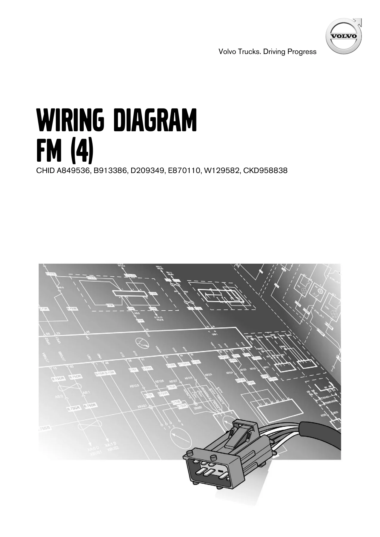
The Volvo FM4 Wiring Diagrams 2019 Release 01 – Order No. 89421116 PDF is a detailed electrical reference for Volvo FM (4) trucks. Issued by Volvo Truck Corporation and based on designs and methods studied up to March 2019, this 366-page PDF brings together the circuit diagrams, network architecture, connector information, harness illustrations and component references needed to trace the truck’s electrical systems accurately. The cover identifies CHID A849536, B913386, D209349, E870110, W129582, CKD958838, making those identifiers important when checking applicability before purchase.
This is far more than a small collection of wiring schematics. The manual begins with communication architecture and then works through a large component-wiring section covering power distribution, engine management, transmissions, braking, suspension, steering, lighting, climate systems, cab equipment, body-builder functions, driver assistance and multiple vehicle networks. Later sections provide illustrated harness and component locations, fuse and relay references, connector pin information, grounding points, trailer connections and a comprehensive component list.
File Details
- Manual type: Wiring diagram
- Brand: Volvo Trucks
- Model: FM (4)
- Language: English
- Page count: 366 PDF pages
- File format: PDF
- Order number: 89421116
- Release: Release 01
- Date: 03.2019
Electrical Systems and Vehicle Configurations Covered
The Volvo FM4 2019 wiring diagram manual covers a wide spread of electrical configurations rather than only one isolated circuit group. Engine-related diagrams include interfaces and networks plus D11 and D13 arrangements for multiple emission configurations. The index identifies D11 EM-EU3/4/5 and EXT-SCR EM-EU6 circuits, along with D13 EM-EC01, EM-EC06/EM-EU5, EM-EU6, GT-LNG EM-EU6 and Turbo Compound EM-EU6 applications. Aftertreatment coverage includes EM-EU5 and EM-EU6 systems, AdBlue tank control, and high-pressure liquid gas circuits.
Transmission wiring is provided for manual transmission interfaces, gearbox and retarder circuits, I-SHIFT, Powertronic and retarder arrangements. Brake and chassis electrical sections include ABS, EBS control units and axle modulators, pad-wear warning, front and rear air suspension, air management, hydraulic and electronic steering, rear axle steering, extra axle steering and bogie-lift circuits. This gives technicians a connected electrical view of systems that often interact through shared power supplies, control modules and data networks.
Cab and body systems are equally well represented. The diagrams address exterior and interior lighting, trailer connections, washer and wiper circuits, climate control, water and air parking heaters, fuel-hose heating, roof cooler, comfort accessories, audio and infotainment, cameras, horns, doors, seats, sunroof, cab tilt, tire-pressure monitoring, lubrication, body-builder electrical centers, PTO-related wiring, auxiliary lighting, driver-assistance systems, SRS, alcolock, alarm and telematics functions.
Chapters Covered
- Communication bus architecture
- Component wiring diagrams
- Illustrations
- Fuses
- Relays
- FRC (A01) connectors
- Wiring harness layout
- Ground connections
- List of connectors
- List of trailer connections
- List of components
- Abbreviations
- Cable colour code
Communication bus architecture
The opening technical section maps the truck’s communication structure. Separate architecture diagrams are provided for LIN and CAN networks, including CAN arrangements associated with EM-EC01/EM-EC06/EM-EU5 and EM-EU6. These pages show how control units and networked modules are interconnected, providing a useful starting point when a fault appears to involve communication between several electronic systems rather than a single hard-wired circuit.
Component wiring diagrams
This is the largest working section of the manual. It starts with power supply and starting circuits, power distribution, main switches, key switch, instruments, tachograph, VMCU, cab IO modules and telematics, then continues through engine and aftertreatment systems. Detailed diagrams identify circuit paths, connectors, components and wiring references for D11 and D13 engine configurations, AdBlue functions, gas-related systems, transmission controls, differential locks, retarders, ABS/EBS and chassis systems.
The component diagrams continue through suspension and steering, road and construction lighting, trailer wiring, climate and heating systems, cab electrical equipment, body-builder installations and active-safety systems. The manual also includes backbone, cab, chassis, infotainment and security subnets, switch-module topology, OBD interface wiring and numerous grounding circuits. Because each diagram is identified by its system code, the index can be used to move directly from a circuit name to the corresponding electrical drawing.
Illustrations
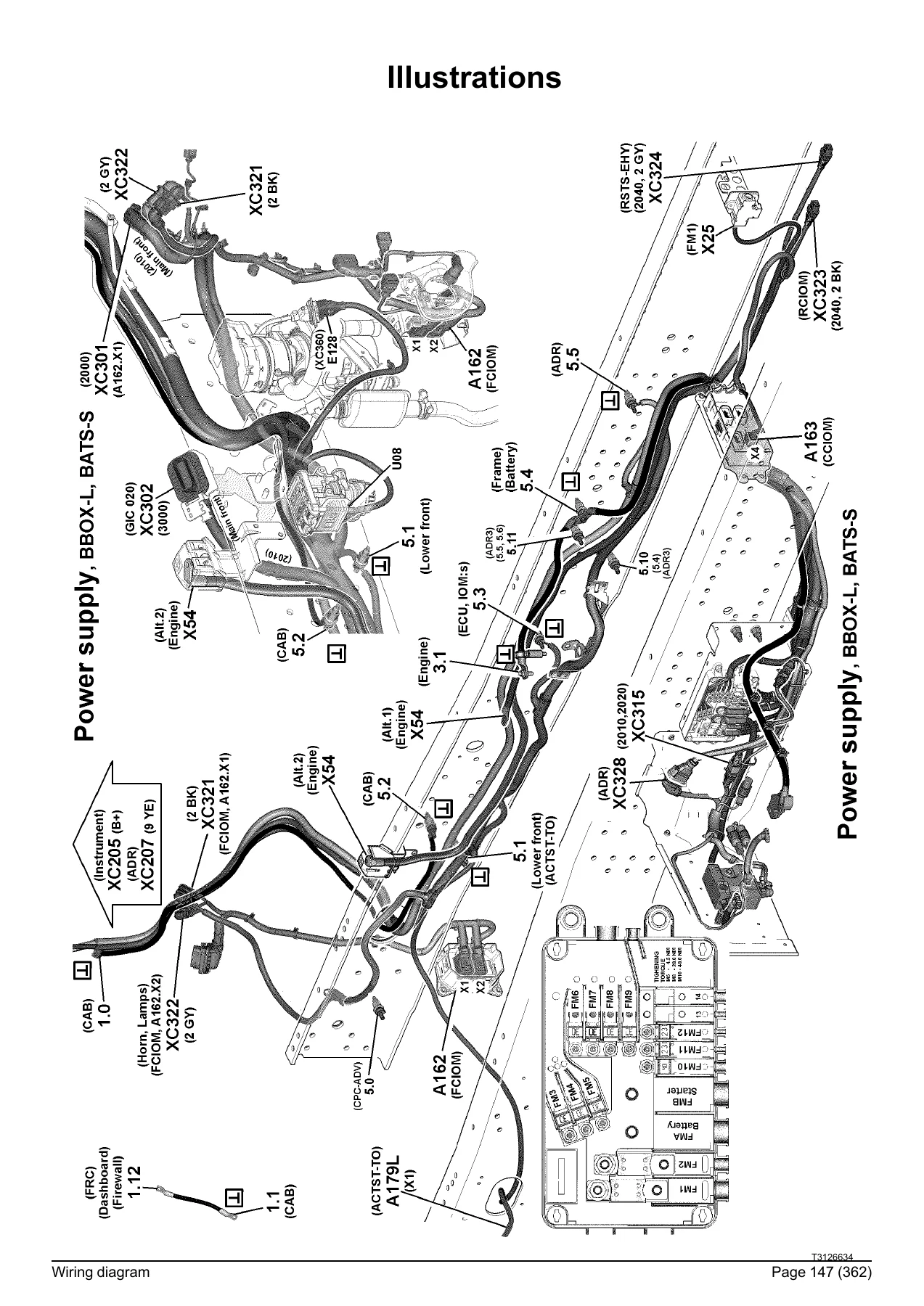
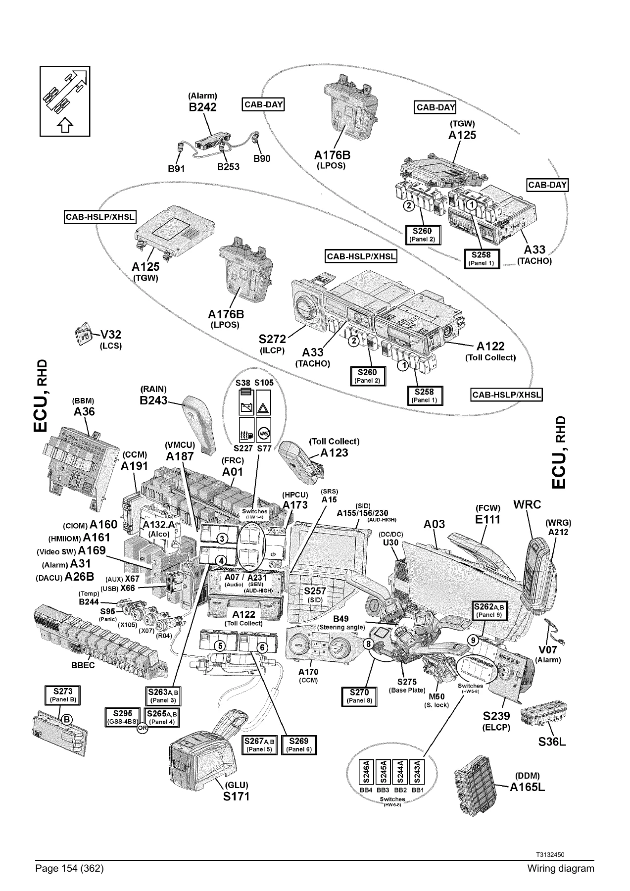
The illustrations section changes from schematic circuit representation to physical-location drawings. It includes power-supply layouts, grounding locations, fuse and relay center illustrations, ECU and antenna locations, switch references, cab-inlet information and extensive harness routing. Harness groups shown in the manual include instrument, front shelf, roof rear shelf, rear wall, door, firewall, lower front, main front, battery box, SCR, main rear, side-marker light, ABS/EBS, RAS-EC, body-builder, engine, gearbox and retarder wiring.
These location drawings are especially valuable when the electrical schematic has identified a component or connector but the next task is finding it physically on the truck. The drawings label modules, connectors, harness paths and installation points so the schematic and physical layout sections can be used together.
Fuses and relays
The fuse section identifies individual fuse positions and their assigned circuits, with references back to the relevant wiring-diagram coordinates. Entries cover supplies for body-builder equipment, seats, HMIIOM, BBM, door modules, tachograph, instruments, VMCU, mirrors, driver assistance, APM, ABS/EBS, climate control, engine management, cab tilt, trailer ABS/EBS, wipers, OBD, power outlets, telematics, parking heaters, SRS and other equipment. Main fuses in the battery box are also identified.
The relay section performs the same function for relay-controlled loads. It identifies relays for the refrigerator, wipers, body-builder electrical center, accessories, roof lighting, beacon lamps, TECU, mirror heating, engine management, cab tilt pump, auxiliary working lamps, engine preheating, starter motor, fuel heater and additional circuits. This provides a direct reference when checking whether a failed electrical function involves its protected supply or control relay.
FRC connectors, wiring harness layout and grounding
The FRC (A01) connector pages list connector designations, pin numbers, circuit functions, wiring numbers and corresponding diagram references. Examples include cab tilt, trailer ABS/EBS, wiper functions, APM, engine-management supplies, climate control, DACU, SRS, body-builder supplies and cab electrical outputs. This pin-level information is useful when following a wire through the Fuse and Relay Centre rather than stopping at the module boundary shown on the primary schematic.
The wiring harness layout and ground sections complement these tables with physical routing and ground-point references. The manual provides a dedicated list of ground connections with diagram cross-references, allowing the user to trace a circuit not only through its powered side but also through its chassis or cab grounding path.
Connector and trailer connection references
The extensive connector list records pin assignments, circuit functions, wiring numbers and the diagrams in which each connection appears. The entries cover cab, chassis, engine, transmission, aftertreatment, safety, lighting, telematics, body-builder and other interfaces. Examples include network high/low lines, sensor supplies and grounds, lighting feeds, engine-management power, transmission signals, AdBlue circuits and body-builder connector pins.
A separate trailer-connection section documents ABS/EBS and lighting connectors, including pin functions for supply, ground, CAN, direction indicators, brake lights, parking lights, fog lights, reverse lights and 24-volt supply circuits. Connections for 7-pole and 15-pole arrangements are included where shown in the manual.
List of components, abbreviations and cable colour code
The component list acts as a large cross-reference between component identifiers and their functions. Control units, sensors, lamps, relays, motors, switches, solenoid valves, connectors and other electrical devices are named and linked back to diagram coordinates or harness groups. It includes equipment such as the VMCU, CIOM modules, engine and transmission control components, EBS hardware, driver-assistance electronics, aftertreatment sensors, lighting equipment and numerous cab devices.
The abbreviation section explains the shorthand used throughout the Volvo FM (4) wiring diagrams, including ABS, APM, BBEC, CIOM, DACU, EAS, EBS, FMS, FRC, PTO, SCR, SRS, TECU and many configuration codes. The cable colour code then defines the standard wiring abbreviations such as BK, BN, BU, GN, GY, OG, RD, VT, WH and YE, plus the alternative colour notation used for engine and transmission wiring. This makes it easier to translate a schematic wire designation into the physical wire being inspected.
A Practical Electrical Reference for Fault Tracing
The real strength of this 2019 Volvo FM4 wiring diagram PDF is the way its different reference sections work together. A technician can start with a system-specific schematic, follow the circuit through control units and connectors, check its fuse or relay, identify connector pin functions, locate the relevant harness or module in an illustration, verify grounding points and use the component list to decode identifiers encountered along the route. That makes the manual useful for structured fault tracing rather than relying on visual inspection or guesswork.
Whether the job involves a starting or power-supply problem, an engine-management circuit, transmission electronics, ABS/EBS, suspension controls, lighting, cab accessories, body-builder wiring, trailer connections, aftertreatment equipment or a communication-network issue, the Volvo FM (4) Wiring Diagram 89421116 Release 01 provides the circuit-level information needed to investigate the system using the correct connections and references.
Get the Volvo FM4 Wiring Diagrams Instantly
For workshops, fleet maintenance teams, auto electricians and technicians working on compatible Volvo FM (4) trucks, having the correct wiring reference available can save substantial time during electrical diagnosis and repair. Instead of tracing circuits without a map, this manual gives you the wiring paths, control-module relationships, fuse and relay assignments, pin references, physical component locations, harness routing and grounding information needed to approach electrical work systematically.
IMAGES PREVIEW
Your purchase is supplied as an instant PDF download. There is no physical book and no shipping delay. Open the Volvo FM4 2019 wiring diagrams on a computer, tablet or other PDF-capable device, keep the complete manual available in the workshop, and print the pages you need for the job. For electrical fault tracing where the right diagram, connector reference or wire identification can make the difference between a quick diagnosis and hours of unnecessary testing, this is a comprehensive working reference for the FM (4).
Reviews
There are no reviews yet.