
Volvo FL Wiring Diagrams Manual 2006 – Complete Electrical Schematics PDF
Original price was: $44.95.$29.95Current price is: $29.95.
Complete 140-page Volvo FL wiring diagrams manual (Order 20020657, Release 01, 2006). Full electrical schematics, fuses, relays, harness layouts, ground points and connector pinouts for the Volvo FL truck.
Description
Volvo FL Wiring Diagrams Manual 2006 – Complete Electrical Schematics
This Volvo FL Wiring Diagrams Manual (Order number 20020657, Release 01, dated 2006) is the complete electrical schematic reference for the Volvo FL truck. Running to 140 pages, it gives technicians and auto-electricians the full circuit-level documentation needed to trace faults, verify connections and repair the electrical system of the FL range. Every diagram follows Volvo’s standard schematic conventions, with wire numbers, colour codes, connector pin references and component coordinates printed directly on the drawings.
Unlike a general repair guide, this is a dedicated Volvo FL wiring diagram resource: it does not cover mechanical overhaul or engine internals, but it documents the electrical network in exhaustive detail. If you are chasing an intermittent fault, rebuilding a harness, adding a body-builder circuit or simply need to know which pin feeds which lamp, this is the document you reach for.
File Details
- Manual type: Wiring diagrams / electrical schematics
- Brand: Volvo
- Model: Volvo FL
- Language: English
- Page count: 140
- File format: PDF
- Document number: 20020657
- Release: Release 01
- Date: 2006
- Publisher: Volvo Truck Corporation, Göteborg, Sweden
Chapters Covered
- Component wiring diagram index
- Component wiring diagrams
- Illustrations index
- Illustrations
- Fuses
- Relays
- Wiring harness illustration index
- Ground connections
- List of ground connections
- List of connectors
- List of components
- Abbreviations
Component Wiring Diagrams
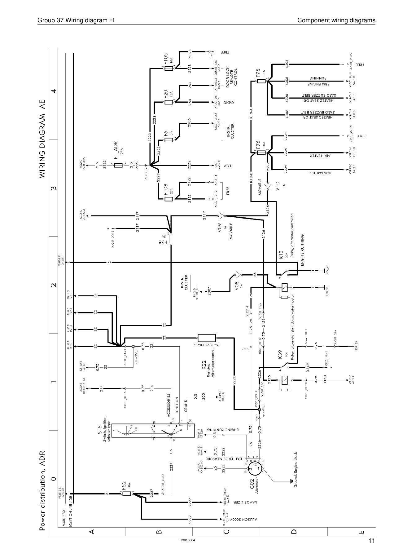
The core of the manual is the component wiring diagram section, which breaks the FL’s electrical system into individual circuits by function. Each diagram shows the circuit from power source through fuse and relay to the end component, with wire numbers, cross-sectional area, connector references and coordinates printed along every conductor. Coverage includes Power Distribution (including UADR and AB variants), the Vehicle ECU (VECU) wiring, parking lights with relay K34, fog lights and extra high beam control, reverse and brake lights, diagnostics connections, windscreen wiper and washer, LCM and flasher unit, horn, heated adjustable mirrors, central locking and immobiliser, rear window lift, sun roof, body builder connectors PB1 to PB5, and the J1708/J1587 and J1939 data bus wiring. The diagrams are drawn to the maximum variant set, and the manual clearly notes that not every wire or component is standard for every market or vehicle model.
How the Diagrams Are Organised
The manual opens with a short reference on wiring numbers and the equipotential system. Wire numbers are grouped by family, so the first digit tells you the circuit type at a glance: 1 for ground and negative supply, 2 for positive supply, 3 for signals, 4 for comfort accessories, 5 for security accessories, 6 for lighting, 7 for instrumentation, 8 for body builder circuits, 9 for free circuits and 0 for electronic/data links. Every diagram also carries a coordinate grid (for example A1, B3, C4) so you can cross-reference a component to its location in the illustration section without hunting through the whole file. A title block on each drawing gives the component, the variant and subtitle, and the key to the symbols used, including switches, relays, splices, fuses and connector terminal callouts.
Illustrations
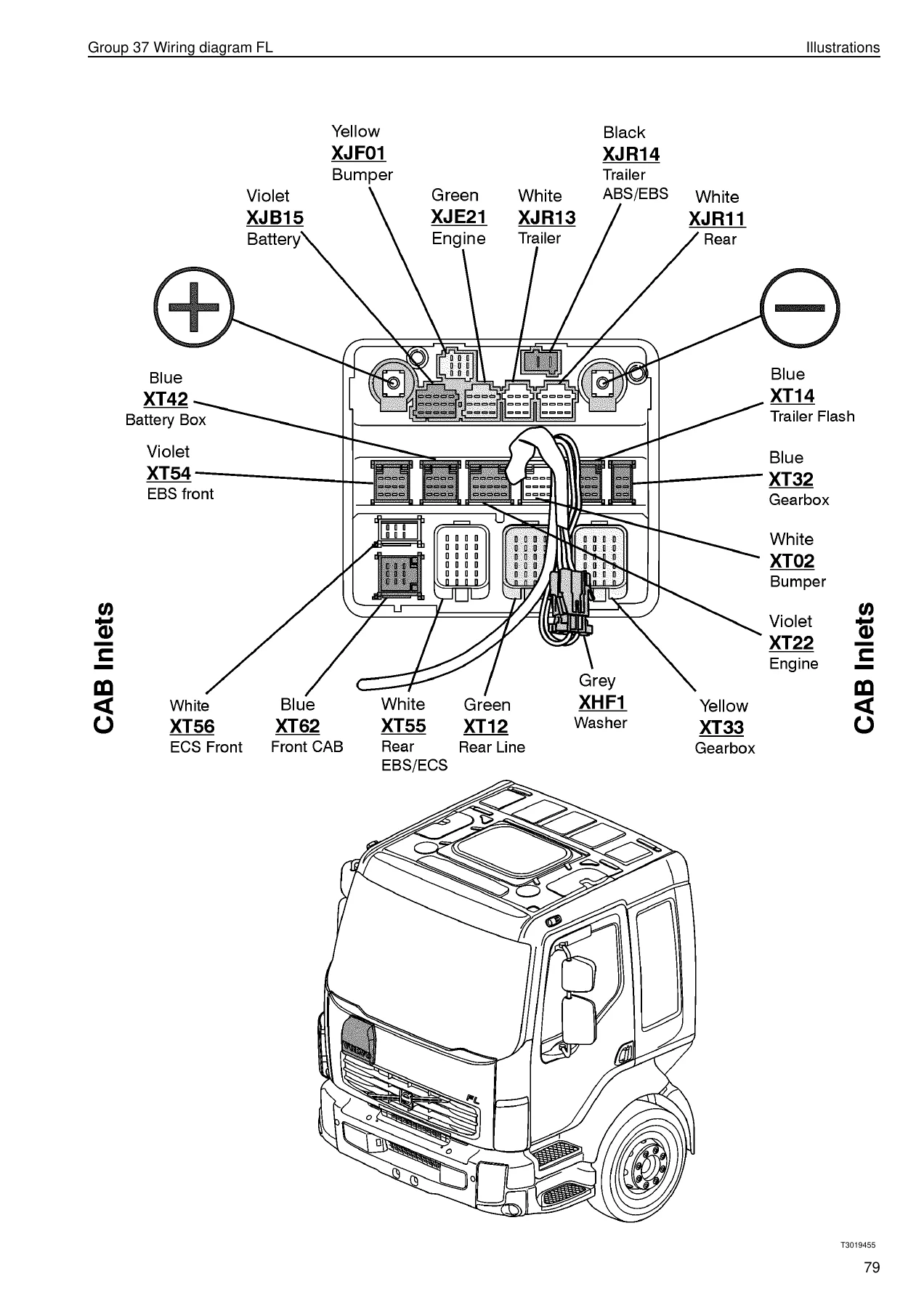
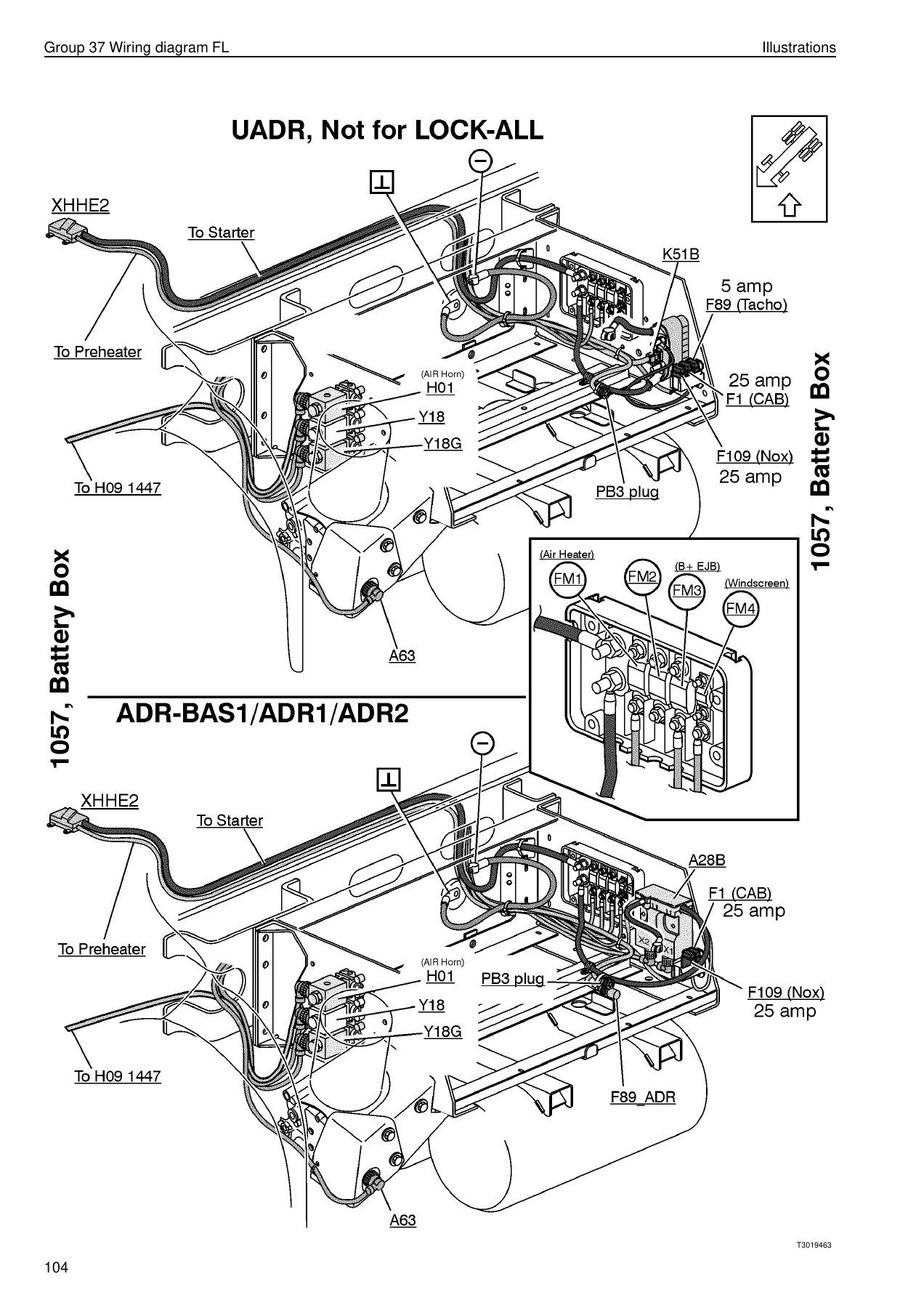
The illustration section moves from schematic to physical layout. Wiring harness illustrations show where each harness runs on the vehicle, with component callouts for driver-side LHD and RHD, passenger side, steering wheel, roof, floor, chassis, engine, frame, gearbox, cab-to-gearbox, door, bumpers, upper front and roof beacon light. Fuse and relay box illustrations show the physical position of every fuse and relay in the cab and battery box, along with connector face views so you can identify a plug before you pull it.
Fuses and Relays
A dedicated fuse list maps every fuse number (F1 through F109 plus the FM fuse groups) to its circuit, location and current rating. The relay section does the same for the relay array, so you can identify which relay feeds which subsystem without guessing. This is the fastest way to isolate a dead circuit before you start pulling panels.
Ground Connections and Connectors
The ground connection list gives every ground point by number and location, which is invaluable when chasing voltage-drop faults. The connector list runs to several pages and indexes every plug by connector code and pin, with the diagram coordinate for each pin. A complete component list and abbreviation glossary close out the reference material.
Why This Volvo FL Wiring Manual Matters
Electrical faults on a commercial truck are rarely solved by swapping parts. They are solved by understanding the circuit: where the power comes from, which fuse protects it, which relay switches it, which connector carries it and where it grounds. This Volvo FL wiring diagram manual gives you that entire chain in one document, in the manufacturer’s own reference format. Whether you run a workshop, maintain a fleet or work on your own FL, having the correct schematics in front of you turns hours of guesswork into a straightforward trace.
IMAGES PREVIEW
Delivered as an instant PDF download, the manual is ready to use the moment payment clears. No shipping, no waiting for a disc in the post. Open it on a laptop in the cab, a tablet on the bench or a phone in the yard, and print the pages you need for the job at hand. The PDF keeps the original 2006 release intact, so every order number, diagram coordinate and fuse reference matches the truck in front of you.


Reviews
There are no reviews yet.