
Volvo FM FH NH12 Wiring Diagram Manual 20176779 – Group 37 Electrical Service PDF
Original price was: $59.95.$39.95Current price is: $39.95.
Complete Volvo FM, FH and NH12 Group 37 wiring diagram service manual, document 20176779. 240-page PDF covering component wiring diagrams, fuses, relays, ground connections, connector pinouts, harness illustrations and cable colour codes for electrical diagnosis and repair.
Description
This Volvo FM FH NH12 wiring diagram manual is the complete Group 37 electrical service reference for Volvo FM, FH and NH12 trucks — document number 20176779, published by Volvo Truck Corporation in June 2006. Across 240 pages it delivers the full component wiring diagram set, fuse and relay data, connector pinouts, ground connection tables, wiring harness illustrations and cable colour codes required to trace, diagnose and repair the electrical systems on these vehicles. Whether you are chasing a fault in the vehicle ECU, repairing a chassis harness, or rebuilding a cab electrical system, this PDF puts the complete factory wiring reference on your screen.
File Details
- Manual type: Wiring diagram service manual
- Brand: Volvo
- Models covered: FM, FH, NH12
- Document number: 20176779
- Manual group: Group 37
- Publication date: June 06
- Language: English
- Page count: 240
- File format: PDF
- Issuing body: Volvo Truck Corporation, Göteborg, Sweden
Chapters Covered
- Component wiring diagram index
- Component wiring diagrams
- Illustrations
- Fuses
- Relays
- Wiring harness illustration index
- Ground connections
- List of ground connections
- List of connectors
- List of components
- Abbreviations
- Cable colour code
Component Wiring Diagrams
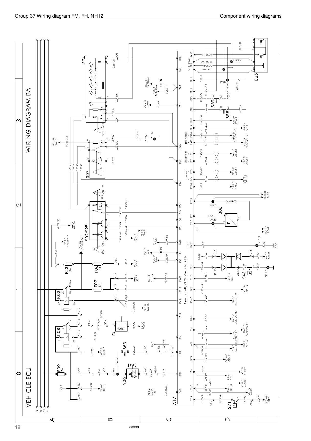
The core of this manual is its component wiring diagram set, covering the complete electrical architecture of the FM, FH and NH12. Diagrams are organised by variant code — BA (Vehicle ECU), BM (Tachograph), BX (Fleet Management System), CK/CM/CO (Engine Interface, D12D, D9B/D13A/D16C4/D16E), CV (SCR/AdBlue), DB/DI/DM/DN/DO/DQ (transmission, Powertronic, I-Shift, Geartronic), EE and EO (EBS), FA (air suspension/A-ride), FK (RHD A-ride with ATB bogie lift), FP (PSS-Dual dual steered front axle), FU (central lubrication), GC (RHD rear lights), GD (LCM fusebox HID relays), GF (India/Korea rear lights), GH (tractor), GQ (horn), GU (headlight adjust), HM (water heater), HZ (air cooler), IA (electrically heated/adjustable seat), IF (foldable mirror bracket), IH (interior light), IM (central locking/immobiliser), IR (12V power supply), IS (SRS airbag), IU (radio), IX (integrated telephone), KA (cab tilt), KE (load light/5th wheel lamp), KI (light sign), KM (beacon warning light), ME (extra fuse block), NA (body builder), NC (body builder ELCE-CK/BBM/PTO2), NI (spotlamps), NK (burglar alarm), NU (dual speed), OA (tyre pressure monitoring), XA/XB/XC (data buses) and ZA RHD (ground/misc). Each diagram shows wire routing, connector pin numbers, splice points, component symbols and reference arrows, so you can follow a circuit from the fuse to the load and back to ground.
Illustrations and Wiring Harness Diagrams
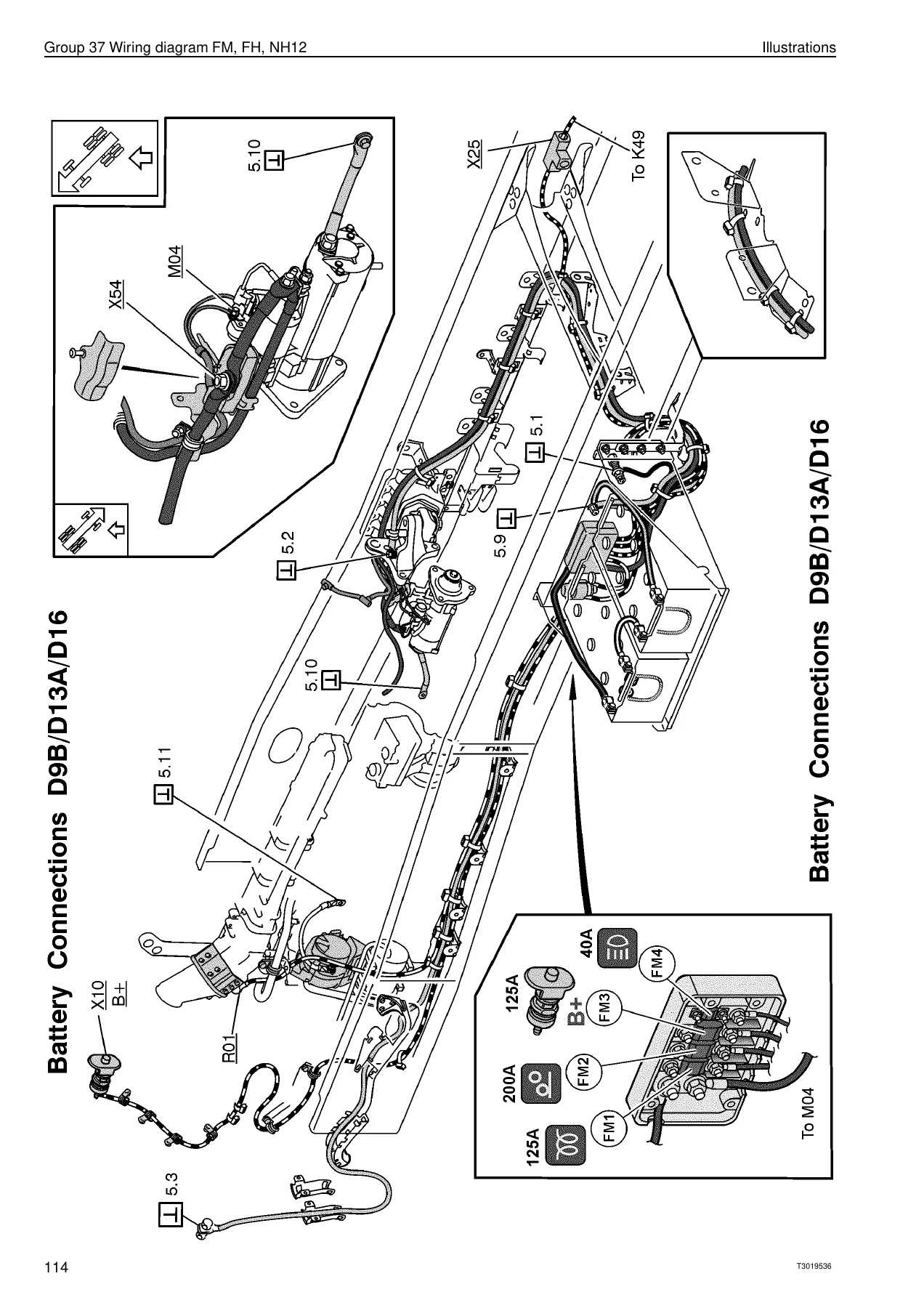
The illustration section provides physical routing views for the major harnesses: instruments (1000 LHD/RHD), roof, floor, air conditioning, cowl, engine-chassis, engine, bogie lift, frame, roof beacon light, air dryer, parking heater, trailer connections, air suspension chassis, side marking lamps, door, ABS chassis, solenoid valves, retarder, main switch, front wheel drive, cab-battery box, electrically operated mirror arch, load indicator, floor gear shift selector, power steering, gearbox, cab-gearbox, upper front, lower front left/right, firewall, body builder connections, demountable (swap-body), ESP chassis, TPM and SCR. These illustrations show where each harness runs, where it clips, where it grounds, and where each connector sits on the vehicle — invaluable when you are removing or refitting a harness and need to know the exact routing and fastening points.
Fuses and Relays
A complete fuse listing names every fuse (F1 through F97 plus FM1–FM4 main fuses), its circuit, its location and its rating. Relay listings identify K1 through K65, each with function and diagram coordinates. Together these sections let you identify exactly which fuse or relay protects a given circuit, and where to find it in the fuse and relay centre.
Ground Connections, Connectors and Components
The ground connection list maps every earth point (1.1 through 5.11 and beyond) to its diagram coordinates, so you can quickly locate and test the correct ground for any circuit. The connector list runs through hundreds of connectors — ADR, AG, AR, AS, AWD, BAB, BB, BCD and on through the alphabet — each with pin assignments and diagram references. The component list identifies every sensor, switch, solenoid, relay, lamp, motor, control unit and connector by its component code (A01 through Y88), with its description and diagram location.
Abbreviations and Cable Colour Code
A full abbreviation glossary decodes terms such as ABS, ACC, ADR, ATB, AWD, BBM, EBS, ECS, FMS, LCM, LHD, PTO, RHD, SCR, SRS, TECU, TPM, VECU and many more. The cable colour code section lists every wire colour abbreviation — BL, BN, GN, GR, OR, P, R, SB, VO, W, Y — and explains the two-colour notation (for example Y/R = Yellow/Red) used throughout the diagrams.
Why This Wiring Diagram Manual Matters
Electrical faults on a heavy truck are rarely solved by guesswork. Without the correct wiring diagram you are left probing connectors, hoping to find the right pin, and risking damage to sensitive control units. This manual removes that guesswork. Every circuit is drawn with its wire colour, cross-section, connector pin and splice point. You can trace a non-starting engine, a dead instrument cluster, a trailer light fault, an EBS warning or an AdBlue system error directly to the affected wire or component. Fuse and relay tables let you check protection first, and ground connection lists let you verify earth integrity before condemning a component.
IMAGES PREVIEW
Instant PDF Delivery
This Volvo FM FH NH12 wiring diagram manual is delivered as an instant PDF download — no shipping, no waiting. Open it on any laptop, tablet or smartphone in the workshop, print only the diagram pages you need for the job, and keep the complete 240-page reference on hand for every electrical repair. Whether you maintain a single truck or a fleet, having the Group 37 wiring diagrams at your fingertips shortens diagnosis time and gets the vehicle back on the road faster.
Reviews
There are no reviews yet.