
Volvo Penta 9L 12L 13L 16L EMS 2 Electrical System Workshop Manual
Original price was: $34.95.$19.95Current price is: $19.95.
144-page Volvo Penta workshop manual covering Group 30 Electrical System for 9L, 12L, 13L, and 16L industrial engines with EMS 2. Includes fault codes, wiring diagrams, sensor specifications, and fault tracing procedures.
Description
Volvo Penta 9L, 12L, 13L, 16L Industrial Engines (EMS 2) — Group 30 Electrical System Workshop Manual
This Volvo Penta 9L 12L 13L 16L EMS 2 Electrical System Workshop Manual is the Group 30 service publication for industrial engines equipped with the EMS 2 (Engine Management System). It delivers the technical data, design descriptions, component explanations, fault tracing procedures, fault code tables, measurement values, and wiring diagrams needed to diagnose and repair the electrical system on these engines.
Produced for Volvo Penta workshops and qualified technicians, the manual assumes a fundamental knowledge of the product and the ability to carry out mechanical and electrical work to trade standard. Every procedure, specification, and fault code entry is written specifically for the 9L, 12L, 13L, and 16L engine families running EMS 2 electronics.
File Details
- Manual type: Workshop Manual (Group 30 — Electrical System)
- Brand: Volvo Penta
- Models covered: 9L, 12L, 13L, 16L Industrial Engines (EMS 2)
- Language: English
- Page count: 144
- File format: PDF
- Publication number: 47701632
- Edition / date: 05-2021
Chapters Covered
- 00-0 General — General Information, Spare Parts, About this Workshop Manual, Repair Instructions, Tightening Torque, Sealing Compounds, Safety Regulations for Fluorocarbon Rubber
- 03-3 Specifications, Electrical — Technical Data for switches, sensors, alternator, and starter motor
- Engine Protection Map
- 05-1 Safety Instructions — Safety Information, warning symbols, and risk precautions
- 08-2 Special Service Tools — break-out cables, multimeter, VODIA diagnostic tool, measuring tools
- 30-0 General — Design and Function: EMS 2, CAN communication, CIU, DCU, DU, fuel control, diagnostic function, component descriptions
- 30-2 Fault Tracing — General, cables and connectors, Fault Codes (MID 128, PID, PPID, SID, FMI), Measurements
- 37-0 Wiring Diagrams — engine-specific wiring schematics and connector pinouts
- 39-0 General — Index
The electrical system section opens with technical specifications for every sensor and switch on the engine: water-in-fuel switch, fuel pressure sensor, crankshaft and camshaft speed sensors, oil pressure sensor, air inlet pressure / inlet manifold temperature combination sensor, coolant temperature sensor, coolant level switch, alternator, starter motor, crankcase pressure sensor, oil level / temperature combination sensor, piston cooling pressure switch, and air filter pressure / temperature combination sensor. Each entry lists voltage, connector pin count, working pressure range, pressure signal, working temperature range, sensor type, and maximum tightening torque where applicable.
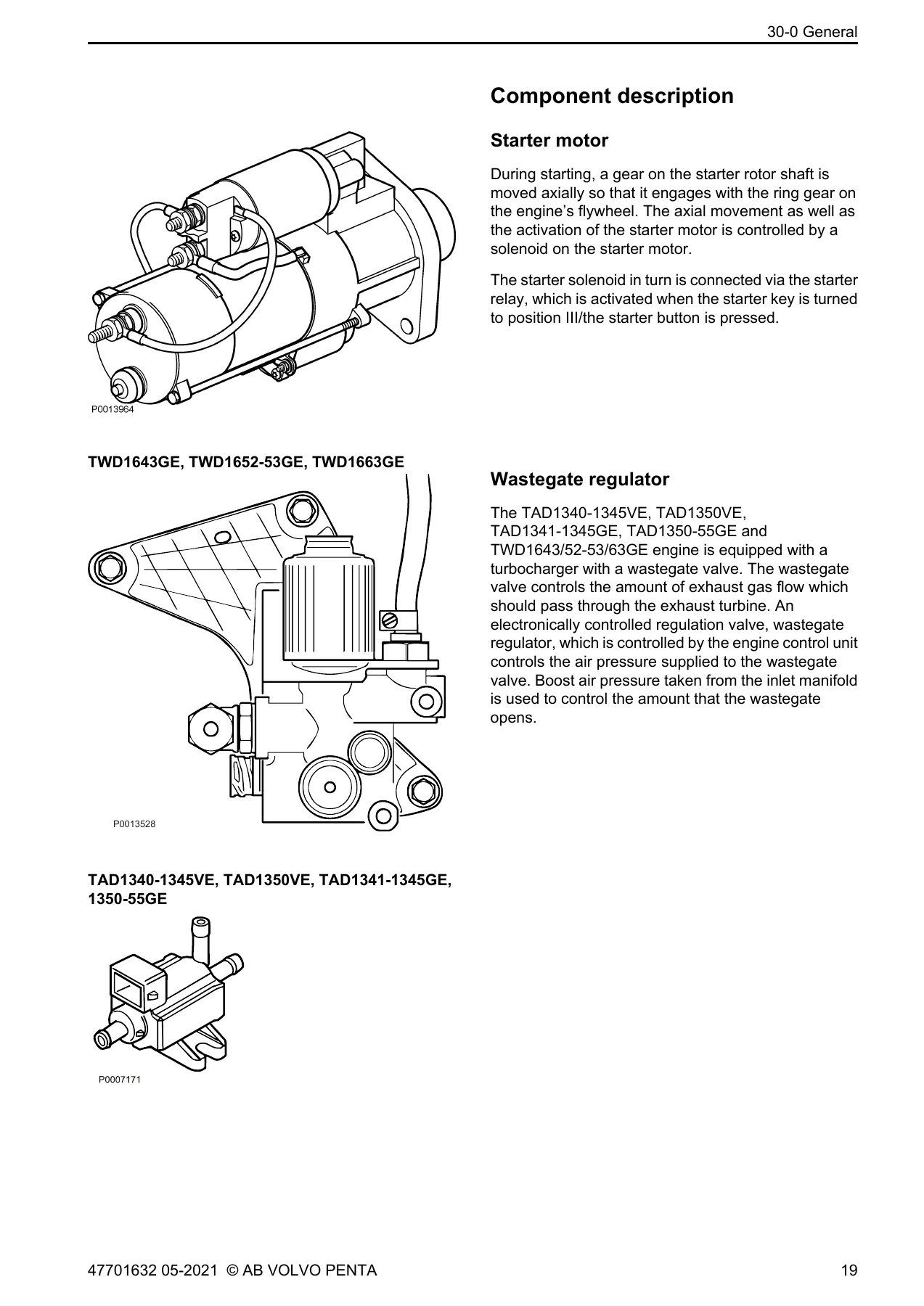
The design and function chapter explains the EMS 2 system architecture, including CAN communication (J1939 and J1708/J1587 links), the CIU (Control Interface Unit), DCU (Display Control Unit), and DU (Display Unit). It describes how the control unit calculates fuel quantity and injection timing based on signals from the speed sensors and the combined boost pressure / boost temperature sensor, and how the diagnostic function detects and localizes malfunctions. Component descriptions cover the starter motor, alternator, unit injectors, crankshaft and camshaft speed sensors, air inlet pressure / inlet manifold temperature sensor, oil pressure sensor, IEGR (Internal Exhaust Gas Recirculation), oil level / temperature sensor, air filter pressure / temperature sensor, crankcase pressure sensor, water-in-fuel switch, exhaust temperature sensor, coolant level switch, cold start valve, preheat relay, control unit EMS 2, coolant temperature sensor, piston cooling switch, fuel pressure sensor, and wastegate regulator.
The fault tracing chapter provides a comprehensive fault code reference organized by MID (Message Identification Description), PID (Parameter Identification Description), PPID (Proprietary PID), SID (Subsystem Identification Description), and FMI (Failure Mode Identifier). Each fault code entry includes the FMI type, fault code explanation, fault indication (DCU display, CIU flash code, electrical fault code, value fault code), symptoms, conditions for the fault code, possible reasons, and suitable actions. Covered fault codes include fan speed sensor, inlet air heater status, fuel delivery pressure, water in fuel indicator, engine oil level, engine oil pressure, intake manifold temperature, air inlet pressure, air filter pressure drop, barometric pressure, engine coolant temperature, coolant level, crankcase pressure, ECU battery potential, inlet air temperature, exhaust gas temperature, engine oil temperature, engine speed, starter output, starter input sensor, key off input sensor, piston cooling oil pressure, internal EGR status, ECU temperature, engine sync acknowledge, throttle calibrated position, thermostat, injectors, engine position, timing sensor crank, wastegate output driver, fan clutch output, air inlet heater driver, sensor supply voltage, SAE J1939 data link, 5 V supply, program memory, SAE J1708/J1587 data link, calibration memory EEPROM, and controller 1.
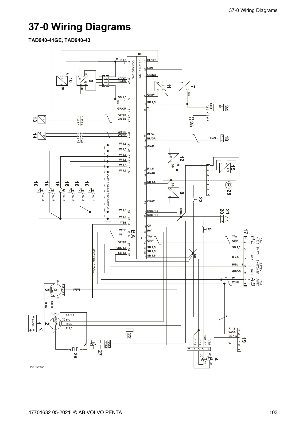
The measurements chapter provides sensor value tables for intake manifold temperature, coolant temperature, air filter temperature, oil temperature, exhaust temperature, and oil / fuel / crankcase pressure, along with procedures for checking the wastegate valve on TWD1643GE, TWD1652GE, TWD1653GE, and TWD1663GE engines. The wiring diagrams chapter includes full-page schematics for engine variants including TAD950-952VE, TAD1250-1252VE, TAD1340-1345VE, TAD1350VE, TAD1341-1345GE, TAD1350-55GE, TAD1650-51GE, TAD1360VE through TAD1365VE, TWD1643GE, TWD1652-1653GE, and TWD1663GE, with component identification, cable colors, and cross-section data.
Additional sections cover repair instructions for working with EMS engines, electrical welding precautions, lost e-key procedures for EVC2, engine control unit replacement, charging system checks, alternator fault tracing (brushes, regulator, rotor), manual fault tracing in bus cables, and measuring engine cables.
What This Manual Enables You to Do
With this Volvo Penta EMS 2 electrical system workshop manual, you can systematically diagnose electrical faults using the MID/PID/SID/FMI fault code structure, trace wiring faults using the engine-specific wiring diagrams, test sensors and actuators against the published specifications, verify charging system performance, replace the engine control unit, and perform measurements on the wastegate valve and other components. The fault code tables alone provide a complete diagnostic framework for the EMS 2 system across all covered engine variants.
Having the correct fault code explanations and measurement values means you can identify the actual cause of a problem instead of replacing parts by guesswork. The wiring diagrams let you trace circuits accurately, and the specifications ensure sensors and switches are tested against the values Volvo Penta specifies.
IMAGES PREVIEW
This Volvo Penta 9L 12L 13L 16L workshop manual is delivered as an instant PDF download — no shipping, no waiting. You can access it on any device, print the pages you need for the workshop, and keep the complete electrical system reference on hand for every service and repair.


Reviews
There are no reviews yet.